FWD-32LX2F - Computer monitor SONY - Free user manual and instructions
Find the device manual for free FWD-32LX2F SONY in PDF.

User questions about FWD-32LX2F SONY
0 question about this device. Answer the ones you know or ask your own.
Ask a new question about this device
Download the instructions for your Computer monitor in PDF format for free! Find your manual FWD-32LX2F - SONY and take your electronic device back in hand. On this page are published all the documents necessary for the use of your device. FWD-32LX2F by SONY.
USER MANUAL FWD-32LX2F SONY
Flat Wide Display Monitor
| 取扱説明書 | JP |
| Operating Instructions | GB |
| Mode d'emploi | FR |
| Bedienungsanleitung | DE |
| Manual de instrucciones | ES |
| Istruzioni per l'uso | IT |
| 使用说明书 | CS |
Sony Corporation. Printed in China
SRS(○)® BBE® WOW DIGITAL
© 2006 Sony Corporation
安全のために
natural_image
Technical line drawing of a mechanical component with dimension label '5' and hatched fill (no text or symbols beyond basic lines)单位:cm
ご注意
②/ [图标] (→ I N P U T)
text_image
FIGUCCOMPONENT ACTIVE THILOGYnatural_image
Simple geometric diagram with a central circle surrounded by six smaller circles, no text or symbols present.![SONY FWD-32LX2F - ②/ [图标] (→ I N P U T) - 1](/content/2026/04/679615/images/bc630c3850a1f1ba3b45901e70b37b54f68faca8a2f6c7dac442de29d1faac56.jpg)
ワイド ズーム
![SONY FWD-32LX2F - ②/ [图标] (→ I N P U T) - 2](/content/2026/04/679615/images/89a1bd37c473cbd741840142b5cefd5e76e15132c32eb10328b0a26efda7053f.jpg)
natural_image
Simple geometric diagram with a central circle surrounded by five smaller circles, no text or symbols present.4:3
![SONY FWD-32LX2F - ②/ [图标] (→ I N P U T) - 3](/content/2026/04/679615/images/749927768b5a98c2c7299d198bf292fc8c26f592b96031ceb63503f0caf1b1d1.jpg)
natural_image
Simple geometric diagram with a central circle surrounded by six smaller circles, no text or symbols present.フル
![SONY FWD-32LX2F - ②/ [图标] (→ I N P U T) - 4](/content/2026/04/679615/images/226537a37c37c1d4266aa86119c0587da28caa61bd2142a4d1cfdb44bd420b10.jpg)
natural_image
Simple geometric diagram with a central circle surrounded by four smaller circles, no text or symbols present.ズーム
![SONY FWD-32LX2F - ②/ [图标] (→ I N P U T) - 5](/content/2026/04/679615/images/874bb70a7d59f607799b79220d334c86727bba1f22d62e6a6be74a0209053240.jpg)
natural_image
Geometric diagram with a central circle surrounded by smaller semicircles and rectangles (no text or symbols)16:9 の映像ソース
natural_image
Diagram showing two rectangular blocks with circles inside, one decreasing and the other increasing (no text or symbols)ワイドズーム
natural_image
Two geometric diagrams showing circles inscribed within rectangles, no text or symbols present4:3
natural_image
Two abstract geometric diagrams with circles and rectangles, no text or symbols presentフル
natural_image
Two geometric diagrams showing circles inside rectangles, one with a central circle and the other with an oval (no text or symbols)ズーム
natural_image
Two abstract geometric patterns: one with white circles on a gray background, the other with white circles on a gray background (no text or symbols)ご注意
natural_image
Simple geometric diagram with a central circle surrounded by four smaller circles, enclosed in a square frame (no text or symbols)フル1
natural_image
Simple geometric diagram with a central circle surrounded by five smaller circles, no text or symbols present.フル2
natural_image
Simple diagram with a central oval and four surrounding empty circles arranged in a symmetrical pattern (no text or symbols)2 画面設定を使う
FWD-32LX2F/32LX2X:120 W
スピーカー出力
7W + 7W(6)
適合負荷インピーダンス
6 \~ 16 Ω
動作条件
温度:0 \~ 35 ℃
湿度:20 ~ 90%
(結露のないこと)
保存·輸送条件
温度:- 10 \~+ 40 ℃
湿度:20 \~ 90%
(結露のないこと)
外形寸法
FWD-40LX2F :
988 × 591 × 125 mm
FWD-40LX2X :
994 × 597 × 125 ~mm
FWD-32LX2F :
796 × 486 × 107 ~mm
FWD-32LX2X :
802 × 492 × 107 ~mm
(幅/高さ/奥行き、最大突起部含まず)
質量
FWD-40LX2F :
約 25.0 kg
FWD-40LX2X :
約 26.0 kg
FWD-32LX2F :
約 16.0 kg
FWD-32LX2X :
約 17.0 kg
付属品
電源コード (1)
AC プラグホルダー (2)
ケーブルホルダー
2画面設定 19, 25, 30, 32
2画面ボタン 16,19
4:3 18, 29, 30
4:3 映像 25, 30
A
AC INソケット 15,21
IP Address Setup 25, 35
L
LED 31
M
Manual
(IP Address Setup) 35
MENUボタン 11,16
N
NR (ノイズリダクション) 24, 26
0
True Color Control 24, 27
V
VIDEO IN/OUT端子 13
WARNING
Owner's Record
The model and serial numbers are located on the rear. Record the model and serial numbers in the spaces provided below. Refer to these numbers whenever you call upon your Sony dealer regarding this product.
Model No. ____ Serial No. ____
To reduce the risk of fire or electric shock, do not expose this apparatus to rain or moisture.
To avoid electrical shock, do not open the cabinet. Refer servicing to qualified personnel only.
On transportation
When you carry the display unit, hold the unit itself, not the speakers. If you fail to do so, the speakers may come out of the unit and the unit may fall. This can cause injury.
For customers in the U.S.A.
If you have any questions about this product, you may call; Sony Customer Information Services Center 1-800-222-7669 or http://www.sony.com/
Declaration of Conformity
Trade Name: SONY
Model: FWD-40LX2F/FWD-
40LX2X/FWD-32LX2F/
FWD-32LX2X
Responsible Party: Sony Electronics Inc.
Address: 16530 Via Esprillo, San
Diego, CA 92127 U.S.A.
Telephone Number: 858-942-2230
This device complies with Part 15 of the FCC Rules. Operation is subject to the following two conditions: (1) This device may not cause harmful interference, and (2) this device must accept any interference received, including interference that may cause undesired operation.
This equipment has been tested and found to comply with the limits for a Class B digital device, pursuant to Part 15 of the FCC Rules. These limits are designed to provide reasonable protection against harmful interference in a residential installation. This equipment generates, uses, and can radiate radio frequency energy and, if not installed and used in accordance with the instructions, may cause harmful interference to radio communications. However, there
is no guarantee that interference will not occur in a particular installation. If this equipment does cause harmful interference to radio or television reception, which can be determined by turning the equipment off and on, the user is encouraged to try to correct the interference by one or more of the following measures:
- Reorient or relocate the receiving antenna.
- Increase the separation between the equipment and receiver.
- Connect the equipment into an outlet on a circuit different from that to which the receiver is connected.
- Consult the dealer or an experienced radio/TV technician for help.
You are cautioned that any changes or modifications not expressly approved in this manual could void your authority to operate this equipment.
For customers in Canada
This class B digital apparatus complies with Canadian ICES-003.
The socket-outlet should be installed near the equipment and be easily accessible.
CAUTION
RISK OF EXPLOSION IF BATTERY IS REPLACED BY AN INCORRECT TYPE. DISPOSE OF USED BATTERIES ACCORDING TO THE LOCAL RULES
Trademark Information
WOW, SRS and (● symbol are trademarks of SRS Labs, Inc. WOW technology is incorporated under license from SRS Labs, Inc.
Manufactured under license from BBE Sound, Inc. Licensed by BBE Sound, Inc. under one or more of the following US patents: 5510752, 5736897. BBE and BBE symbol are registered trademarks of BBE Sound, Inc.
Table of Contents
Introduction
Precautions 4
Recommendations on Installation....6
Location and Function of Parts and Controls
Front Panel....7
Side Panel....8
Optional Adaptors 10
Rear Panel 11
Remote Control....12
Button Description....12
Special Buttons on the Remote Control....14
Using the Wide Mode....14
Using the PAP Setting 15
Using the ID MODE button 16
Using the ECO Mode function 16
Connections
Connecting the Speakers....17
Connecting the AC Power Cord 17
Cable Management....18
Using the Settings
Overview of the Menus 20
Picture Settings....22
Sound Settings....24
Screen Settings....25
Setup Settings....29
Other Information
Troubleshooting 32
Input Signal Reference Chart....33
Specifications 34
Index 36
Introduction
Precautions
On safety
- A nameplate indicating operating voltage, power consumption, etc. is located on the rear of the unit.
- Should any solid object or liquid fall into the cabinet, unplug the unit and have it checked by qualified personnel before operating it any further.
- Unplug the unit from the wall outlet if it is not to be used for several days or more.
- To disconnect the AC power cord, pull it out by grasping the plug. Never pull the cord itself.
- When you install the unit on the floor, be sure to use the optional display stand.
On installation
- Allow adequate air circulation to prevent internal heat build-up. Do not place the unit on surfaces (rugs, blankets, etc.) or near materials (curtains, draperies) that may block the ventilation holes.
- Do not install the unit in a location near heat sources such as radiators or air ducts, or in a place subject to direct sunlight, excessive dust, mechanical vibration or shock.
- When you install multiple equipment with the unit, the following problems, such as malfunction of the remote control, noisy picture, noisy sound, may occur depending on the position of the unit and other equipment.
On the LCD panel
- You may see some bright spots of red, blue or green, or dark spots appearing on the screen. These do not indicate a malfunction. Although the LCD panel is manufactured with extremely high precision technology, it can generate a few dark or bright pixels.
- Keeping the LCD panel facing toward the sun for a long time will damage the panel. Take this into account when you install the unit outdoor or by a window.
- Do not push, scratch or put a heavy weight on the panel. These can cause irregularities in the screen or a malfunction of the LCD panel.
- You may find the screen looks darker or an afterimage occurs when using the unit in a colder environment. These do not indicate a malfunction. The screen will return to normal operation as the temperature rises.
- If you display a still image continuously, a ghosting may occur. This symptom will be gradually resolved by changing the image or making the whole screen display in white. In addition, if you display the same still image for a long period of time, the ghosting may not be resolved.
- The panel surface or the cabinet may warm up during use. This does not indicate a malfunction.
On cleaning the display
The panel surface
- Be sure to unplug the power cord before cleaning the display.
- The LCD panel surface has been given a special finish. Avoid touching the LCD screen. When cleaning the panel face, wipe off stains using a dry, soft cloth.
- Never use rubbing alcohol, benzine or thinner for cleaning. They may damage the finish of the panel face.
- When using a chemically treated cloth for cleaning, follow the directions.
- Spraying the unit with volatile solvents (such as an insecticide) or allowing the unit come into prolonged contact with rubber or plastic products may remove the coating or spoil the unit.
The cabinet
- Gently wipe off stains using a dry, soft cloth. Wipe off grimy stains using a cloth slightly moistened with a mild detergent, then wipe the area again using a dry, soft cloth.
- Never use rubbing alcohol, benzine or thinner for cleaning. They may damage the finish of the cabinet or can remove the markings on it.
Notes on handling and cleaning the display panel
The display panel's special surface finish should be treated with care when cleaning or handling the display. When cleaning it, use a soft cleaning cloth to avoid touching the panel directly.
On repacking
Do not throw away the carton and packing materials. They make an ideal container in which to transport the unit. When shipping the unit, repack it as illustrated on the carton.
If you have any questions on this unit, contact your authorized Sony dealers.
Disposal of Waste Electrical and Electronic Equipment for business use (Applicable in the European Union and other European countries with separate collection systems)

natural_image
Symbol of a trash bin crossed with two crossed lines and a solid rectangle below (no text or labels)This symbol on the product or on its packaging indicates that this product shall not be treated as household waste. Instead it shall be handed over to the applicable take-back scheme for the recycling of electrical and electronic equipment. By ensuring this product is disposed of correctly, you will help prevent potential negative
consequences for the environment and human health, which could otherwise be caused by inappropriate waste handling of this product. The recycling of materials will help to conserve natural resources. For more detailed information about recycling of this product, please contact your local Sony office or visit Sony Europe's web site for business customers: http://www.sonybiz.net/environment
For the State of California, USA only
Perchlorate Material – special handling may apply, See www.dtsc.ca.gov/hazardouswaste/perchlorate Perchlorate Material : Lithium battery contains perchlorate.
For Customers in the United States
Lamp in this product contains mercury. Disposal of these materials may be regulated due to environmental considerations. For disposal or recycling information, please contact your local authorities or the Electronic Industries Alliance (www.eiae.org).
For Customers in Taiwan only
廢電池請回收

Warning on power connection
Use the proper power cord for your local power supply.
| United States, Canada | Continental Europe | United Kingdom, Ireland, Australia, New Zealand | Japan | ||
| Plug type VM0233 COX- | 07 636 — | a) | VM1296 | ||
| Female end VM0089 COX | -02 VM0310B VM | M0303B VM | 1313 | ||
| Cord type SVT H05VV-F | CEE (13) 53rd (O.C) HVCTF | ||||
| Minimum cord set rating | 10A/125V 10A/250V | 10A/250V | 10A/125V | ||
| Safety approval | UL/CSA | VDE VDE | DENAN-HO | ||
a) Note: Use an appropriate rating plug which complies with local regulations.
Recommendations on Installation
Provide an ample amount of space around the display
- To prevent internal heat buildup from scaling off the display, make sure to ensure proper ventilation by leaving open the minimum amount of space around the display, as illustrated below.
- The ambient temperature must be 0 °C to 35 °C (32 °F to 95 °F).
- When using the stand, make sure you use the applicable display stand SU-42FW/32FW (not supplied).
- Regarding the installation of hardware such as brackets, screws, or bolts, we cannot specify the products. Actual installation is up to the authorized local dealers. Consult with qualified Sony personnel for installation.
- While the display is on, a certain amount of heat builds up inside. This can cause burns. Avoid touching the top or rear of the display when it is powered on or just after it has entered standby mode.
When using the display stand
Front
text_image
20 (7^7/8) 10 (4) 10 (4)Side
text_image
10 (4)Units: cm (inches)
When mounting the display horizontally Front
text_image
25 (9 7/8) 10 (4) 10 (4) 25 (9 7/8)Side
Units: cm (inches)
When mounting the display vertically
Front
text_image
20 (7 7/8) 25 (9 7/8) 1 10 (4) 25 (9 7/8) Make sure that the ⏻ POWER switch is at the lower right.Side
natural_image
Technical line drawing of a mechanical assembly with no visible text or symbols5 (2)
Units: cm (inches)
Notes
- When mounting the display vertically, you cannot use the speakers SS-SP40FW/32FW (not supplied).
- Be sure to use only the UL listed wall mount bracket to mount the display.
Location and Function of Parts and Controls
Front Panel
text_image
MENU 1 2 3 4 5 R POWER/STANDBY 6 7 8①MENU (page 20)
②/ (INPUT)
- In the menu screen, this button works as the "Set" button.
- This button switches the input signal when it is not in the menu screen.
Selects an input signal from among the HD15/HDMI 1/HDMI 2/OPTION 1/OPTION 2 connectors.
When an optional adaptor is not installed in the OPTION 1/OPTION 2 slot, OPTION 1/OPTION 2 will be skipped.
③/←→
- In the menu screen, these buttons work as left/right buttons.
- In the “PAP” mode, these buttons work to change the active picture or change the picture size when a screen other than the menu screen is displayed.
4/↑/↓
- Increases (+) or decreases (−) the volume.
- In the menu screen, these buttons work as up/down buttons ( /↑, ↓)
5
Switches the display on or off (standby).
Note
To protect the panel, a certain amount of time is required to turn the display to on/off (standby). When you turn the display on again, soon after turning it off, wait about 5 seconds before you turn it on again.
⑥ Sony logo
The Sony logo lights up. You can switch "On"/"Off" in the menu screen. See "Advanced Setup" on page 30.
⑦ Remote control sensor
⑧ POWER/STANDBY indicator
- Lights up in green when the display is switched on.
- Lights up in red when the display is in standby mode.
- Lights up in orange when the display enters the power saving mode when the current input is not video or S Video.
Note
When the “LED” option in the “Multi Display” settings is set to “Off” and the “Position” option is not set to the right-bottom, the indicator does not light up in green even when the display is turned on, except for the case of no signal or an unsupported signal.
Side Panel
To open the cable cover (side)
text_image
OPTION 1 slot (VIDEO/COM) OPTION 2 slot (VIDEO)| Connector Description | |
| 1 AUDIO (COMMON AUDIO IN)(Sterco mini jack) | Inputs an audio signal. Connects to the audio signal output of a piece of video equipment or PC. Supports audio signals corresponding to 2 and 3. |
| 2 HD15 (RGB/COMPONENT IN)(D-sub 15-pin) | Connects to the analog RGB signal or component signal output of a piece of video equipment or PC. See page 35.NoteWhen inputting a component signal, be sure not to input sync signals to pins 13 and 14. If you do so, the picture may not be displayed properly. |
| 3 HDMI 1/HDMI 2 IN | HDMI (High-Definition Multimedia Interface) provides an interface between the display and any HDMI-equipped audio/video equipment, as well as PC. You can enjoy enhanced or high-definition video, and two-channel digital audio. You can also connect a piece of DVI-equipped equipment to your display by using an HDMI-to-DVI cable (not supplied). The appropriate mode for a piece of audio/video equipment or PC is automatically selected in accordance with the connected equipment.NoteBe sure to use only an HDMI cable (not supplied) that bears the HDMI logo. |
| 4 MONITOR CONTROL ADAPTOR(The BKM-FW20 is pre-installed.) | CONTROL S IN/OUT (Mini jack): You can control pieces of multiple equipment with a single remote control when the display is connected to the CONTROL S connector of the video equipment or another display. Connect the CONTROL S OUT connector on this display to the CONTROL S IN connector of the other equipment, and connect the CONTROL S IN connector on this display to the CONTROL S OUT connector of the other equipment.REMOTE (D-sub 9-pin): This connector allows remote control of the display using the RS-232C protocol. For details, contact your authorized Sony dealers.NoteThis adaptor won’t work when installed in the OPTION 2 slot. |
| 5 OPTION 1 slot(VIDEO/COM port) | This slot supports video signals and communication functions. By installing an optional adaptor (the BKM-FW series) in this slot, you can expand the input signal connectors or control the display via the network. |
| 6 VIDEO INPUT ADAPTOR(The BKM-FW10 is pre-installed.) | S VIDEO IN (Mini DIN 4-pin): Connects to the S Video output of a piece of video equipment.S VIDEO OUT (Mini DIN 4-pin): Connects to the S Video input of a piece of video equipment.VIDEO IN (BNC): Connects to the video output of a piece of video equipment.VIDEO OUT (BNC): Connects to the video input of a piece of video equipment.AUDIO IN L/R (Pin jack): Connects to the audio output of a piece of video equipment.The video signal or the S Video signal is automatically selected. Connect the cable (not supplied) to the video connector or the S Video connector.When connecting a piece of video equipment equipped with the S Video output connector, you can enjoy better video performance by connecting it to the S Video connector. |
| 7 OPTION 2 slot(VIDEO port) | This slot supports video signals. You can install an optional adaptor with video signal input/output function into this slot. The optional adaptor with communication functions should be installed in 5 OPTION 1 slot. |
Optional Adaptors
The connectors marked with ⑤ and ⑦ on the side panel are slot-in types and can be fitted with any of the following optional adaptors (not supplied).
For details on installation, consult your Sony dealers.
VIDEO INPUT Adaptor BKM-FW10
This is the same as the optional adaptor preinstalled in the ⑦ OPTION 2 slot. See page 8.
COMPONENT/RGB INPUT Adaptor BKM-FW11
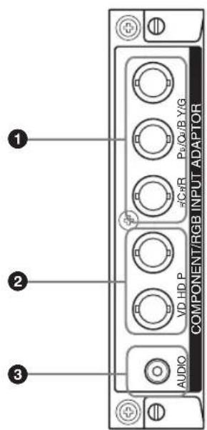
text_image
① ② ③ AUDIO VD HD P COMPONENT/RGB INPUT ADAPTOR 5Cr/R Pe/Cu/B Y/G①Y/G P_B/C_B/B P_R/C_R/R IN (BNC): Connects to the analog RGB signal or component signal output of a piece of video equipment or PC.
②HD VD IN (BNC): Connects to the synchronization signal output of a PC.
Note
When inputting a component signal, be sure not to input sync signals to the HD and VD connectors. If you do so, the picture may not be displayed properly.
3AUDIO (Stereo mini jack): Inputs an audio signal. Connects to the audio output of a piece of video equipment or PC.
RGB/COMPONENT ACTIVE THROUGH Adaptor BKM-FW12
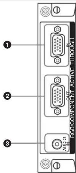
text_image
1 2 3 AUDIO IN OUT RGB/COMPONENT ACTIVE THROUGH①RGB/COMPONENT IN (D-sub 15-pin):
Connects to the component signal output or analog RGB signal output of a piece of video equipment or PC. For details on inputting a component signal to the connector, see "Pin assignment" on page 35.
Note
When inputting a component signal, be sure not to input sync signals to pins 13 and 14. If you do so, the picture may not be displayed properly.
②RGB/COMPONENT OUT (D-sub 15-pin):
Connects to the component signal input or analog RGB signal input of a piece of video equipment or PC.
Inputs an audio signal. Connects to the audio signal output of a piece of video equipment or PC.
Note
When the display is not connected to an AC power or is in the standby mode, no signal is output from the RGB/COMPONENT OUT.
NETWORK MANAGEMENT Adaptor BKM-FW32
For details, see the instruction manual of the BKM-FW32.
STREAMING RECEIVER Adaptor BKM-FW50
For details, see the instruction manual of the BKM-FW50.
Note
When using a network cable for the BKM-FW32/50, be sure to use a shielded cable to help prevent the radiation of undesired radio waves. For details on the connection, see each instruction manual.
For details on the optional adaptors for system expansion, BKM-FW series, see each instruction manual.
Rear Panel
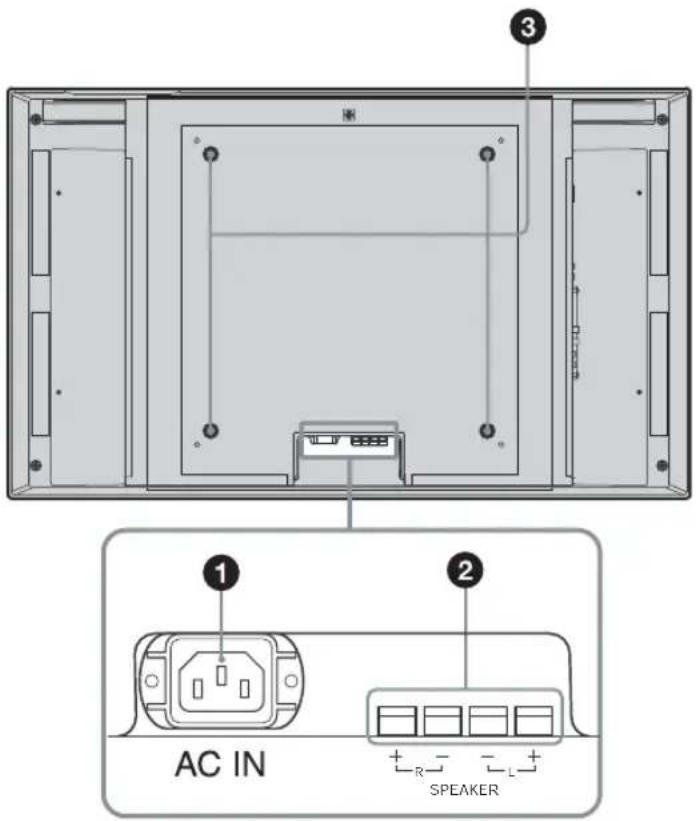
text_image
AC IN SPEAKERGB
Parts Description
| 1 AC IN socket | Connect the supplied AC power cord to this socket and to a wall outlet. Once you connect the AC power cord, the POWER/STANDBY indicator lights up in red and the display goes into the standby mode. See page 17. |
| 2 SPEAKER socket | By connecting the speakers SS-SP40FW/32FW (not supplied) to this socket, you can output the audio matching the signal displayed on the screen and enjoy viewing with a greater sense of presence. Please be sure to connect the speakers correctly. For more details on connecting the speakers, see the operating manual that came with the speakers. For details on how to route the speaker cords, see page 19. |
| 3 Stand installation hooks | Use these hooks to install the display stand SU-42FW/32FW (not supplied). |
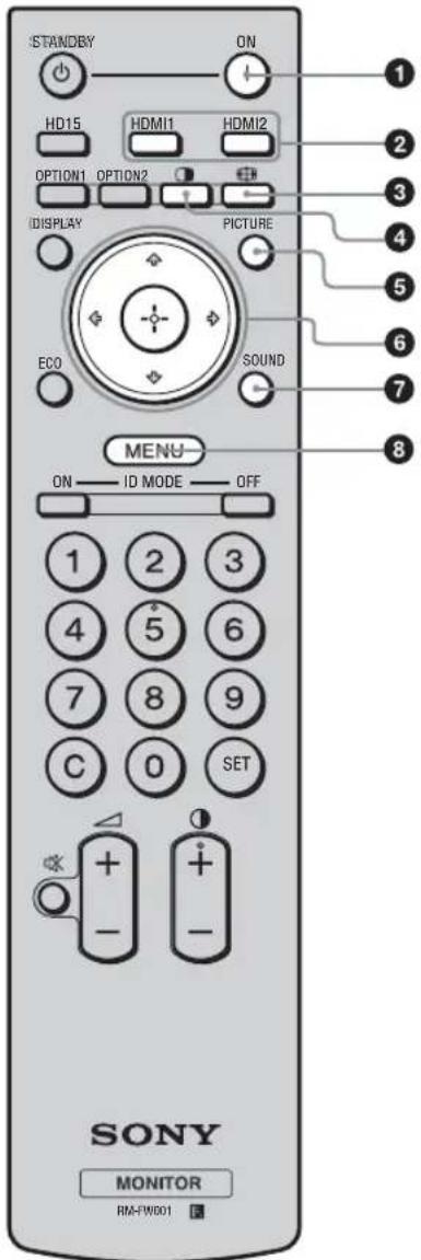
Remote Control
Button Description
text_image
STANDBY ON HD15 HDMI1 HDMI2 OPTION1 OPTION2 IDISPLAY PICTURE ECO SOUND MENU ON — ID MODE — OFF 1 2 3 4 5 6 7 8 9 C 0 SET + - + - SONY MONITOR RM-FW001① POWER ON switch
Press to turn the display on.
②HDMI 1/ HDMI 2 button
Press to select the signal input to the HDMI 1 or HDMI 2 connectors.
③ button
Press to change the aspect ratio in "Wide Mode". See page 14.
④ button
Selects the "PAP" (Picture And Picture) mode. Each press toggles between the two-picture screen and the single-picture screen. See page 15.
⑤PICTURE button
Selects "Picture Mode". Each press toggles between "Vivid", "Standard", "Custom", and "TC Control".
6 ↗/↓/↔/→/⊕ buttons
The ♠/▽/⇨/⇨ buttons move the menu cursor (yellow) and set values, etc. Pressing ⬤sets the selected menu or setting items. In the “PAP” mode, you can switch the active picture with ◁/⇨.
⑦ SOUND button
Selects "Sound Mode". Each press toggles between "Dynamic", "Standard", "SRS WOW", and "Custom".
⑧MENU button
Press to show menus. Press again to hide them. See page 20.
Notes
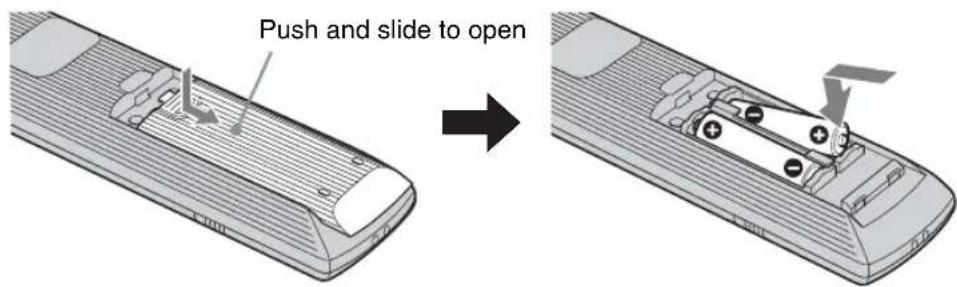
- The 5 button and button have a tactile dot. Use the tactile dot as a reference when operating the display.
- Insert two size AA (R6) batteries (supplied) by matching the and on the batteries to the diagram inside the remote control's battery compartment.
text_image
Push and slide to open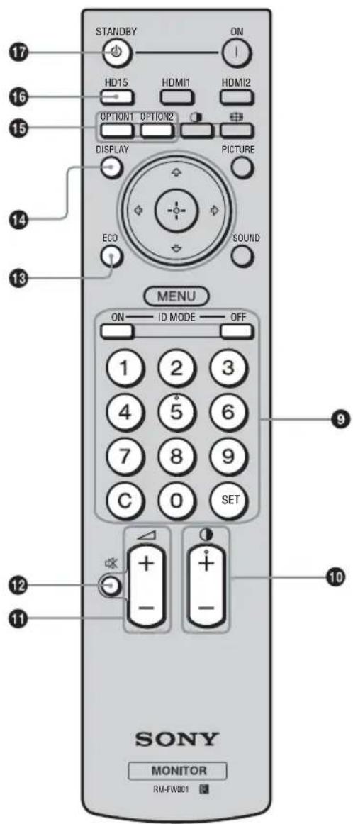
text_image
STANDBY ON HD15 HDMI1 HDMI2 OPTION1 OPTION2 DISPLAY PICTURE ECO SOUND MENU ON ID MODE OFF 1 2 3 4 5 6 7 8 9 C 0 SET SONY MONITOR RM-FW001⑨ID MODE (ON/0-9/SET/C/OFF) buttons
You can operate a specific display without affecting other displays installed at the same time.
- ON button: Press to show the "Index Number" on the screen.
- 0-9 button: Press to enter the "Index Number" of the display you want to operate.
- SET button: Press to set the input "Index Number".
- C button: Press to clear the input "Index Number".
- OFF button: Press to return to the normal mode.
See page 16.
10 +/ button
Adjusts the picture (contrast) level.
⑪ +/- button
Press to adjust the volume.
⑫ button
Press to mute the sound. Press again to restore sound.
⑬ ECO button
Press to reduce the power consumption by adjusting the backlight brightness. This also enhances the black level. Select from "Off", "Low", "High" or "Picture Off". See page 16.
⑭DISPLAY button
Press to display the currently selected input, the type of the input signal and the "Wide Mode" setting on the screen. Press again to hide them. If this displayed information is left undisturbed for a short time, it will disappear automatically.
⑮OPTION 1/OPTION 2 button
When an optional adaptor is installed, selects an input signal from the equipment connected to the optional adaptor. Press the OPTION 1 button to select the input signal of the OPTION 1 connector, and press the OPTION 2 button to select the input signal of the OPTION 2 connector.
16HD15 button
Press to select the input signal of the HD15 connector. The RGB signal or component signal is selected automatically in accordance with the connected equipment.
⑰STANDBY button
Press to change the display to the standby mode.
Special Buttons on the Remote Control
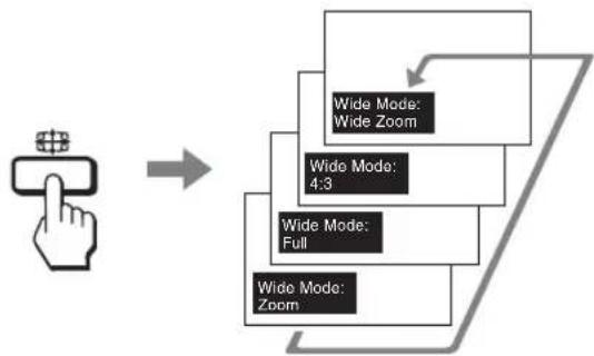
Using the Wide Mode
You can change the aspect ratio of the screen.
Tip
You can also access the "Wide Mode" settings in the "Screen" settings. See page 25, 28.
flowchart
graph TD
    A["User Hand Click"] --> B["-->"]
    B --> C["Wide Mode: Zoom"]
    B --> D["Wide Mode: Full"]
    B --> E["Wide Mode: 4.3"]
    C --> F["Wide Mode: Wide Zoom"]
    D --> G["Wide Mode: Zoom"]
    E --> H["Wide Mode: Zoom"]
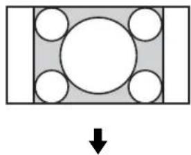
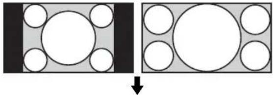
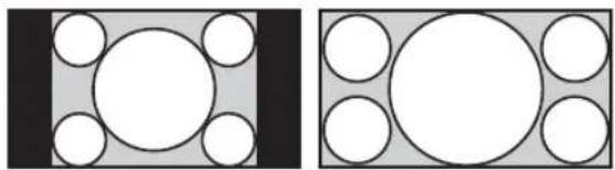
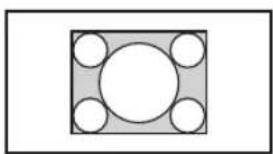
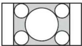
For Video, DVD or HDMI input (other than PC input)
4:3 Original Source
natural_image
Diagram showing a rectangular block with five circular holes and a downward arrow, no text or symbols present.Wide Zoom
natural_image
Simple geometric diagram with a central circle surrounded by four smaller circles, no text or symbols present.4:3
natural_image
Geometric diagram with a central circle surrounded by five smaller circles, enclosed in a rectangle (no text or symbols)Full
natural_image
Simple diagram with a central oval and four surrounding circles, no text or symbols present.Zoom
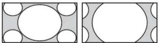
natural_image
Geometric diagram with a central circle surrounded by four semicircles on a gray background (no text or symbols)16:9 Original source
natural_image
Diagram showing two geometric shapes with circles inside, one rotated to form a rectangle (no text or symbols)Wide Zoom
natural_image
Two abstract geometric diagrams with circles and shaded regions, no text or symbols present4:3
natural_image
Two abstract geometric diagrams with circles and rectangles, no text or symbols presentFull
natural_image
Two geometric diagrams showing circles arranged in a grid within rectangles (no text or symbols)Zoom
natural_image
Two abstract geometric patterns: one with white circles on a gray background, the other with white circles on a gray background (no text or symbols)Note
When the input signal is 1080i, 720p, or 1080p, "Wide Zoom" and "4:3" cannot be selected. See page 25.
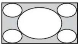
For PC Input
Normal
natural_image
Simple geometric diagram with a central circle surrounded by four smaller circles, enclosed in a square frame (no text or symbols)Full 1
natural_image
Geometric diagram with a central circle surrounded by five smaller circles, no text or symbols present.Full 2
natural_image
Simple diagram with a central oval and four surrounding empty circles arranged in a symmetrical pattern (no text or symbols)Using the PAP Setting
You can show two pictures from different signal sources, such as a PC and a video, side by side.
You can also swap the left/right pictures, or change the balance of left/right picture sizes.
Tip
You can also access the "PAP Setting" in the "Screen" settings. See page 26.


Cursor showing active picture
text_image
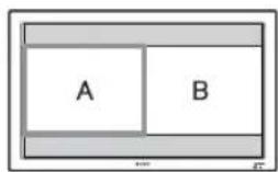
A BThe width of A and B is the same.
The height will be set to match each picture's aspect ratio.

Press ⇔ button.
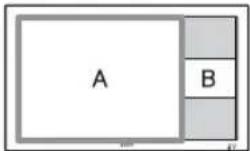
The width of A is larger than that of B.
If A's aspect ratio is 4:3, its height will be equal to the panel size.

Press button.
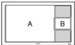
B on the right side becomes the active picture.
Press button.
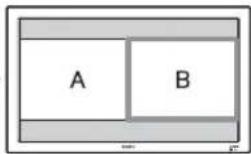
The width of A and B is the same.
The height will be set to match each picture's aspect ratio.

Press button.
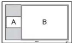
The width of B is larger than that of A.
If B's aspect ratio is 4:3, its height will be equal to the panel size.
Available combination of two pictures
You can operate a specific display without affecting other displays installed at the same time.
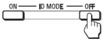
1 Press ON button.
Display's "Index Number" appears in black characters on the lower left menu on the screen. (Every display is allocated an individual preset "Index Number" from 1 to 255.)
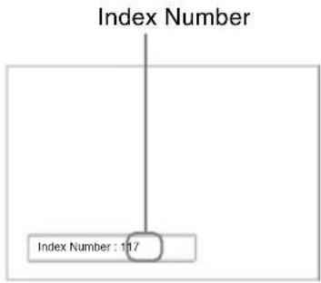
text_image
Index Number Index Number : 117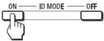
text_image
ON —— ID MODE —— OFF2 Input the "Index Number" of the display you want to operate using the 0 - 9 buttons on the remote control.
The input number appears right next to the "Index Number" of each display.
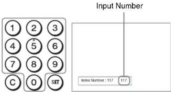
text_image
Input Number 1 2 3 4 5 6 7 8 9 C 0 SET Index Number : 117 1173 Press SET button.
The characters on the selected display change to green while the others change to red.

You can operate the specified display indicated with green characters only.
Only the operation of POWER ON switch and STANDBY/ID MODE-OFF button is effective to other displays, as well.
4 When all of the setting changes have been completed, press OFF button.
The display returns to the normal screen.
text_image
ON — ID MODE — OFFTo correct the Index Number
Press the C button to clear the current input "Index Number". Return to Step 2, and input a new "Index Number".

Tip
To change the "Index Number" of the display, see "Remote Index" in "Control Setting" on page 30.
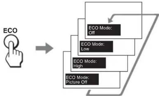
Using the ECO Mode function
You can reduce the power consumption of the display.
flowchart
graph TD
    A["ECO"] --> B["ECO Mode: Off"]
    A --> C["ECO Mode: Low"]
    A --> D["ECO Mode: High"]
    A --> E["ECO Mode: Picture Off"]
To cancel the ECO Mode
Press ECO button repeatedly until "ECO Mode : Off" appears.
Tips
- If you turn off the display when the "ECO Mode" is activated, the mode stays on next time you turn on the display except "Picture Off".
- You can set the "ECO Mode" using the "Setup" settings. Select "ECO Mode" in the "Setup" settings, then set it to "Off", "Low", "High", or "Picture Off".
Connections
Before you start
- First make sure that the power of each piece of equipment is turned off.
- Use cables suitable for the equipment to be connected.
- Connect the cables, fully inserting them into the connectors or jacks. A loose connection may cause hum and other noise.
- To disconnect the cable, pull it out by grasping the plug. Never pull the cable itself.
• See the instruction manual of the equipment to be connected, too. - Insert the plug securely into the AC IN socket.
- Use one of the two AC plug holders (supplied) to securely hold the AC plug.
Connecting the Speakers
You can enjoy viewing with a greater sense of presence by connecting the speakers SS-SP40FW/32FW (not supplied). Please be sure to connect the speakers correctly. For more details on connecting the speakers, see the operating manual of the speakers. For details on how to route the speaker cords, see page 19.
Connecting the AC Power Cord
1 Plug the AC power cord into the AC IN socket. Then, attach the AC plug holder (supplied) to the AC power cord.
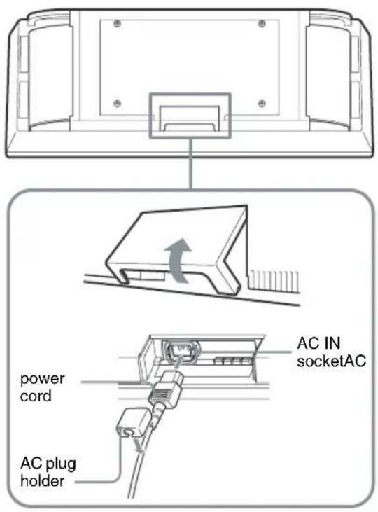
text_image
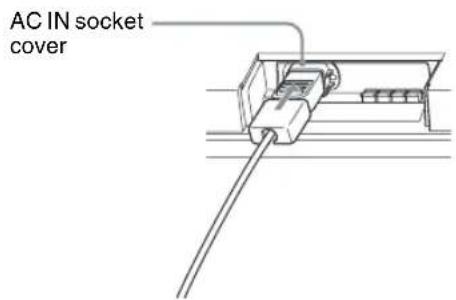
AC IN socketAC power cord AC plug holder2 Slide the AC plug holder over the cord until it connects to the AC IN socket cover.
text_image
AC IN socket coverTo remove the AC power cord
After squeezing the AC plug holder and freeing it, grasp the plug and pull out the AC power cord.
Cable Management
The display has the cable covers on its back to make it look neat. Before connecting the cables to the display, open the cable covers as shown below. After connecting the cables to the display, close the cable covers.
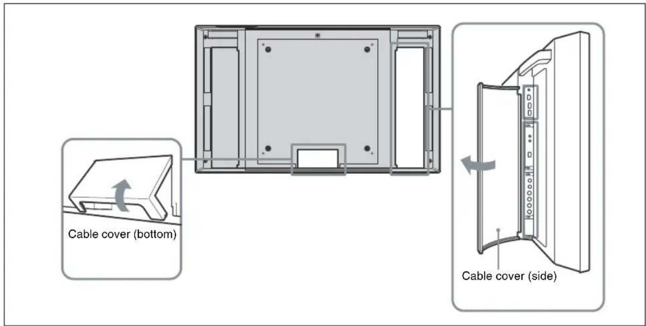
text_image
Cable cover (bottom) Cable cover (side)Using the cable holders
You can bundle the cables with the supplied cable holders.
Attach the cable holders as shown in the illustration below.
For the FWD-40LX2F/40LX2X:
Attach the two cable holders (×4 supplied) to the slits on the top and on the bottom respectively.
When you connect the speakers (not supplied), route the speaker cords through the speaker cord holders on the rear of the display.
For the FWD-32LX2F/32LX2X:
Choose six out of eight holes (4 on the top and 4 on the bottom) and attach the cable holders ( × 6 supplied). The speaker cord holders are not supplied.
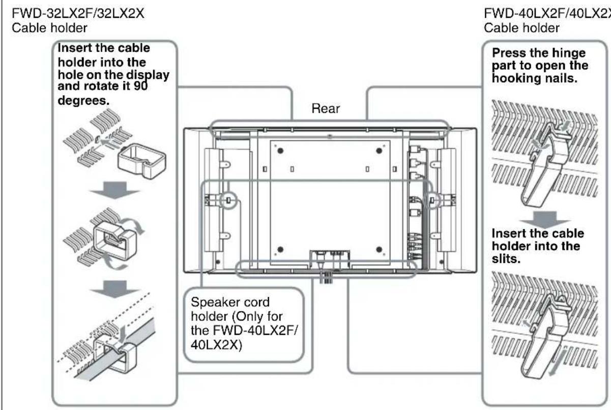
text_image
FWD-32LX2F/32LX2X Cable holder Insert the cable holder into the hole on the display and rotate it 90 degrees. Speaker cord holder (Only for the FWD-40LX2F/40LX2X) Rear FWD-40LX2F/40LX2X Cable holder Press the hinge part to open the hooking nails. Insert the cable holder into the slits.Using the Settings
Overview of the Menus
text_image
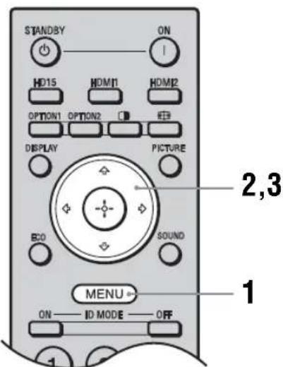
STANDBY ON HD15 HDMI1 HDMI2 OPTION1 OPTION2 DISPLAY PICTURE ECO SOUND MENU ON ID MODE OFF 1 2,3The settings provide you access to the following features:
1 Press MENU button.
2 Press ↗/▽ to highlight the desired menu icon.
3 Press ⊕ or ➔.
To exit the menu, press MENU button.
To change the on-screen language
Select the desired language for on-screen settings and messages from “English”, “Español”, “Français”, “Italiano”, “Deutsch” or “日本語
"English" (English) is set for the default setting.
See page 29.
Settings Allows you to set/change
Picture
text_image
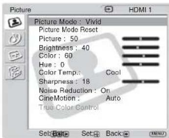
Picture Picture Mode : Vivid Picture Mode Reset Picture : 50 Brightness : 40 Color : 60 Hue : 0 Color Temp: Coal Sharpness : 18 Noise Reduction : On CineMotion : Auto True Color Control Set Back Back (HDMI)Picture Mode (page 22, 23)
Picture Mode Reset (page 22, 23)
Picture (page 22, 23)
Brightness (page 22, 23)
Color (page 22)
Hue (page 22)
Color Temp. (page 22, 23)
Sharpness (page 22)
Noise Reduction (page 22)
CineMotion (page 22)
True Color Control (page 23)
Sound

text_image
Sound Sound Mode : Dynamic Sound Mode Reset Treble : Bass : Balance : Center Common Audio Sel.: HD 15 Speaker Out : OnSound Mode (page 24)
Sound Mode Reset (page 24)
Treble (page 24)
Bass (page 24)
Balance (page 24)
Common Audio Sel. (page 24)
Speaker Out (page 24)
Settings Allows you to set/change
Screen
text_image
Screen HDMI 1 Wide Mode : Wide Zoom Auto Wide : On 4:3 Default : Wide Zoom Display Area : Normal Auto Adjustment Phase : Pitch : Horizontal Shift : 0 Vertical Shift : 0 Vertical Size : 0 Reset PAP Setting Multi Display Set: Exit Set Back:Wide Mode (page 25, 28)
Auto Wide (page 25)
4:3 Default (page 26)
Display Area (page 26)
Auto Adjustment (page 28)
Phase (page 28)
Pitch (page 28)
Horizontal Shift (page 26, 28)
Vertical Shift (page 26, 28)
Vertical Size (page 26)
Reset (page 26, 28)
PAP Setting (page 26)
Multi Display (page 27)
Setup
text_image
Setup Language : English Timer Setting ECO Mode : Off Auto Shut Off : Off Advanced Setup Information All Reset IP Address Setup Speed Setup Sel: Back: Set: ExportLanguage (page 29)
Timer Setting (page 29)
ECO Mode (page 29)
Auto Shut Off (page 29)
Advanced Setup (page 30)
Information (page 30)
All Reset (page 30)
IP Address Setup (page 31)
Speed Setup (page 31)

Picture Settings
For Video Input
text_image
Picture Picture Mode : Vivid Picture Mode Res Standard Picture : Custom Brightness : TC Control Color : 60 Hue : 0 Color Temp.: Cool Sharpness : 18 Noise Reduction : On CineMotion : Auto True Color Control Sel: Exit Set: Back: MENUTo highlight an option and to change settings, press /// .
Press ⓣ to confirm the selection.
The "Picture" settings include the following options:
| Picture Mode | “Vivid”: Select for enhanced picture contrast and sharpness.“Standard”: Select for standard picture settings.“Custom”: Allows you to store preferred settings.“TC Control”: The setting is common with “Vivid”. In addition, you can use the “True Color Control” function (after-mentioned).TipsTo change from one “Picture Mode” option to another, you can also use PICTURE on the remote control instead.You can alter the “Picture Mode” options for each input. |
| Picture Mode Reset | Resets all settings and adjustments to the default setting for the currently selected “Picture Mode” (“Vivid”, “Standard”, “Custom”, “TC Control”) (except for the options grayed out). |
| Picture | Adjust picture contrast. |
| Brightness | Adjust to brighten or darken the picture. |
| Color | Adjust to increase or decrease color intensity. |
| Hue | Adjusts the color tones of the picture.Note“Hue” is not available when the input is video or S Video and the color system of video signal is not NTSC. |
| Color Temp. | “Cool”: Select to give the white colors a blue tint.“Neutral”: Select to give the white colors a neutral tint.“Warm”: Select to give the white colors a red tint. |
| Sharpness | Adjust to sharpen or soften the picture. |
| Noise Reduction | Select to reduce the noise level of connected equipment. Select from “On” or “Off”. |
| CineMotion | Select “Auto” to optimize the screen display automatically detecting film content and applying a reverse 3-2 pull down or 2-2 pull down process. Moving picture will appear clearer and more natural looking. Select “Off” to disable the detection. |
True Color Control
You can adjust the details of hue and saturation for each of 4 colors: red, green, yellow, blue, and you can highlight specific colors in the image. Select the color which you want to adjust, and you can check and see which part of current image will be adjusted. Then you can adjust it using the matrix dialog.
Notes
- This option can be adjusted when “Picture Mode” is set to “TC Control”.
- In “PAP” mode, you cannot select this option. Even if you select this option in the single-picture screen, the setting of this option may not be applied in the “PAP” mode.
Tip
You can alter the “Picture” settings (“Picture”, “Brightness”, “Color”, etc.) for each “Picture Mode”.
Notes
- In the “PAP” mode, none of the options of the “Picture” settings can be selected.
- If there is no signal currently being input, none of the options of the “Picture” setting can be selected.
For PC Input
text_image
Picture Picture Mode : Vivid Picture Mode Reset Picture : 50 Brightness : 40 Color : Hue : Color Temp. : Neutral Sharpness : Noise Reduction : CineMotion : True Color Control : Sel: Exit Set: Back: MENUWhen input is switched to a PC input source, the “Picture” settings specific to PC input are applied. The “Picture” settings for a PC include the following options:
Picture Mode
“Vivid”: Select for enhanced picture contrast and sharpness.
"Standard": Select for standard picture settings.
"Custom": Allows you to store preferred settings.
“TC Control”: The setting is common with “Vivid”. In addition, you can use the “True Color Control” function (after-mentioned).
Picture Mode Reset
Resets all settings and adjustments to the default setting for the currently selected “Picture Mode” (“Vivid”, “Standard”, “Custom”, “TC Control”) (except for the options grayed out).
Picture
Adjust to increase or decrease picture contrast.
Brightness
Adjust to brighten or darken the picture.
Color Temp.
See “Color Temp.” for video input (page 22).
True Color Control
See "True Color Control" for video input (page 23).
Notes
- “Color”, “Hue”, “Sharpness”, “Noise Reduction” and “CineMotion” are not available for PC input.
- In the “PAP” mode, none of the “Picture” settings options can be selected.
- If there is no signal currently being input, none of the options of the “Picture” setting can be selected.

Sound Settings
text_image
Sound Sound Mode : Sound Mode Re Treble : Bass : Balance : Common Audio Sel : HD15 Speaker Out : On Dynamic Standard SRS WOW Custom Center Sel: Exit Set: Back: MENUWhen the speakers SS-SP40FW/32FW (not supplied) are installed, you can set various "Sound" settings.
To highlight an option and to change settings, press /// .
Press ⓣ to confirm the selection.
The "Sound" settings include the following options:
Sound Mode
"Dynamic": Select to enhance treble and bass.
"Standard": Flat setting.
“SRS WOW”: Provides a panoramic stereo audio image by producing deep and rich bass tones and clear treble tones, enabling you to enjoy powerful sound effects like those in a movie theater.
"Custom": Allows you to store preferred settings.
Tips
- To change from one "Sound Mode" option to another, you can also use SOUND on the remote control instead.
- The proprietary technologies of BBE Sound, Inc. are applied for “Dynamic” and “Standard”.
Sound Mode Reset
Resets the following settings; "Treble", "Bass" and "Balance" to the default settings.
Treble
Adjust to increase or decrease higher-pitched sounds.
Bass
Adjust to increase or decrease lower-pitched sounds.
Balance
Adjust to emphasize left or right speaker balance.
Common Audio Sel.
"HD15": Outputs audio from a piece of video equipment or PC connected to the HD15 (RGB/COMPONENT IN) connector and the AUDIO (COMMON AUDIO IN) connector.
"HDMI 1"/"HDMI 2": Select to connect a piece of equipment using an HDMI cable (not supplied) or an HDMI-to-DVI cable, and the corresponding audio cable at the same time.
See page 8.
Notes
- When using an HDMI-to-DVI cable (not supplied), connect the audio cable to the AUDIO (COMMON AUDIO IN) connector.
- When “HDMI 1”/“HDMI 2” is selected, digital audio is not output from the HDMI connectors. When a piece of video equipment equipped with an HDMI connector is connected to the HDMI 1/HDMI 2 connectors, set “Common Audio Sel.” to “HD15”. (The default setting is “HD15”).
Speaker Out
"On": Enables sound to be emitted from the speakers.
"Off": Disables sound to be emitted from the speakers.
Note
When “Speaker Out” is set to “Off”, “Sound Mode”, “Sound Mode Reset”, “Treble”, “Bass”, and “Balance” cannot be selected.
Tip
You can adjust the sound quality menus ("Treble" and "Bass") when the "Sound Mode" is set to "Custom".

Screen Settings
For Video Input
text_image
Screen Wide Mode : Wide Zoom Auto Wide : 4:3 Default : Full Display Area : Zoom Auto Adjustment Phase : Pitch : Horizontal Shift : 0 Vertical Shift : 0 Vertical Size : 0 Reset PAP Setting Multi Display Set: Exit Set: Back: MENUTo highlight an option and to change settings, press /// .
Press ⓣ to confirm the selection.
The "Screen" settings include the following options:
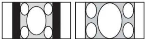
Wide Mode
"Wide Zoom": Select to enlarge to fill screen with minimum distortion.
“4:3”: Select to display 4:3 picture in original size when the original source is 4:3 (Standard definition source).
"Full": Select to enlarge the original picture horizontally to fill the screen when the original source is 4:3 (Standard definition source). When the original source is 16:9 (High definition source), select this mode to display 16:9 picture in original size.
"Zoom": Select to enlarge the original picture without distorting the aspect ratio. See page 14.
Tips
- To change from one "Wide Mode" option to another, you can also use on the remote control.
- Select "Zoom" to display movies and other DVD content with black bands, using the entire viewable area of the screen.
- For “Wide Zoom” and “Zoom” modes, you can adjust “Horizontal Shift”, “Vertical Shift” and “Vertical Size”. See page 26.
Notes
- You cannot set the "Wide Mode" while using the "PAP" function or the "Multi Display".
- "Wide Zoom" and "4:3" cannot be selected for 1080i, 720p, or 1080p signals input to the component or HDMI connectors.
Auto Wide
"On": Select to detect the image and change it automatically to the appropriate screen mode.
"Off": The screen mode does not change automatically.
Notes
- While inputting digital and analog RGB signals, you cannot set the "Auto Wide" because the "Auto Wide" function does not work.
- You cannot set the “Auto Wide” while using the “PAP” function or the “Multi Display” function.
| 4:3 Default | “Wide Zoom”: Select to enlarge the 4:3 picture to fill the 16:9 screen, keeping the original image as much as possible.“4:3”: Select to display the 4:3 picture without changing its aspect ratio.“Full”: Select to enlarge the 4:3 picture horizontally only, to fill the 16:9 screen.“Zoom”: Select to enlarge the 4:3 picture to fill the screen while keeping its aspect ratio. Useful for watching Letterbox movies.“Off”: Select to continue using the current wide screen mode setting when the input is changed.Notes• You can select “4:3 Default” only when “Auto Wide” is set to “On”.• “4:3 Default” functions only when the display receives NTSC, PAL, SECAM, 480i, 480p, 575i or 576p signals.• If “Wide Mode” setting is changed after “4:3 Default” is set, that “Wide Mode” setting will become effective and the aspect ratio of the screen will change. This change of setting made afterward by “Wide Mode” will be effective only for each input signal, therefore when the input signal is changed, the screen will return to the original “4:3 Default” setting. To keep the current aspect ratio even after the input signal is changed, set “4:3 Default” to “Off”. |
| Display Area | “Normal”: Displays a standard size picture.“-1”/“-2”: Allows you to adjust the viewable picture area size. When noises appear around the picture, select this to hide the noises. |
| Horizontal Shift | Allows you to move the position of the picture left and right in the window.Available only in “Wide Zoom” and “Zoom” modes. Press ⇔/⇔ and press ⊕ to choose a correction. |
| Vertical Shift | Allows you to move the position of the picture up and down in the window.Available only in “Wide Zoom” and “Zoom” modes. Press ⇔/⇔ and press ⊕ to choose a correction. |
| Vertical Size | Allows you to adjust the vertical size of the picture. Available only in “Wide Zoom” and “Zoom” modes. Press ⇔/⇔ and press ⊕ to choose a correction. |
| Reset | Resets the following settings; “Horizontal Shift”, “Vertical Shift” and “Vertical Size” to the default settings. |
| PAP Setting | Allows you to show two pictures from different signal sources, such as a PC and a video, side by side. Only the combination of an analog signal and a digital signal is available.“PAP”: “On” shows two pictures side by side at the same time, and “Off” disables “PAP” function.“Swap”: “OK” swaps the position of the two pictures, and “Cancel” aborts the execution.“PAP Size”:“Large Left”: The left picture’s width is larger than the right picture.If the left picture’s aspect is 4:3, the left picture’s height will be equal to the panel size.“Even”: The left picture and the right picture width is the same (half & half). The height will be set to match each picture’s aspect ratio.“Large Right”: The right picture’s width is larger than the left picture.If right picture’s aspect is 4:3, the right picture’s height will be equal to the panel size.Notes• You can show two pictures only when “Multi Display” is set to “Off”.• When two pictures are displayed, the “Picture” settings set when a single picture is displayed are applied.• For details on the available combination of two pictures, see page 15. |
Multi Display
You can make settings for connecting multiple displays to form a video wall.
“Multi Display”: “Off” uses a single screen, and “2×2”-“4×4” selects the arrangement to be used to construct the video wall.
“Position” (location popup): Select the position of this particular display in the arrangement of the video wall with // . Press to set the position.
“Output Format”: Selection of two picture output formats will be available as shown in the figures. By simply selecting either format, suitable picture output will be available without manually adjusting the horizontal and vertical shift.
Select either "Tiles" or "Window".
"Tiles"
text_image
Just scan BC DE FGH FGH FGH BC DETo show full signal on each display.
"Window"
text_image
Over scan B E FCU FCU TGH A TGH B ETo show one large picture with multi display naturally. Part of the signal will go behind the bezel area.
“LED”: “On” causes the POWER/STANDBY indicator on the Front Panel (page 7) to be continually turned on, and “Off” causes the POWER/STANDBY indicator on the Front Panel to be continually shut off.
Notes
- “Multi Display” can display an enlarged picture keeping the current “Wide Mode” setting as much as possible for video input, and can display an enlarged picture of which “Wide Mode” is set to “Full 2” for PC input.
- You can set the “Multi Display” only when the “PAP” function is disabled.
- When the “Position” option is set to the right-bottom, the POWER/STANDBY indicator lights up even if the “LED” option is set to “Off”. The indicator also lights up even when the display is off (standby), errors are detected, or the display is in sleep mode including the case of no signal or unsupported signal.
Notes
- “Display Area”, “Horizontal Shift”, “Vertical Shift”, and “Vertical Size” are not available while using the “PAP” function or the “Multi Display”.
- If there is no signal currently being input, none of the “Screen” settings options, except for “PAP Setting” and “Multi Display” can be selected.
For PC Input
text_image
Screen HD15 RGB Wide Mode : Normal Auto Wide : 4:3 Default : Display Area : Auto Adjustment Phase : 0 Pitch : 0 Horizontal Shift : 0 Vertical Shift : 0 Vertical Size : Reset PAP Setting Multi Display Set Back: MENUWhen input is switched to PC input source, the "Screen" settings specific for PC input are applied. The "Screen" settings for a PC include the following options:
| Wide Mode | “Normal”: Select to display the picture in its original size.“Full 1”: Select to enlarge the picture to fill the display area in the vertical direction, keeping its original horizontal-to-vertical aspect ratio. A black frame will appear on the surrounding of the picture.“Full 2”: Select to enlarge the picture to fill the display area.NoteYou cannot set the “Wide Mode” while using the “PAP” function or the “Multi Display” function. |
| Auto Adjustment | Select to automatically adjust the display position and phase of the picture when the display receives an input signal from the connected PC.Note that “Auto Adjustment” may not work well with certain input signals. In such cases, manually adjust the options below. |
| Phase | Select to adjust the phase when the screen flickers. |
| Pitch | Select to adjust the pitch when the picture has unwanted vertical stripes. |
| Horizontal Shift | Allows you to move the position of the picture left and right in the window. Press ⇔/⇨ and press ⏻to choose a correction. |
| Vertical Shift | Allows you to move the position of the picture up and down in the window. Press ⇔/⇨ and press ⏻to choose a correction. |
| Reset | Resets the following settings; “Phase”, “Pitch”, “Horizontal Shift” and “Vertical Shift” to the default settings. |
| PAP Setting | See “PAP Setting” for video input (page 26). |
| Multi Display | See “Multi Display” for video input (page 27). |
Notes
- "Auto Wide", "4:3 Default", "Display Area" and "Vertical Size" are not available for PC input.
- If there is no signal currently being input, none of the "Screen" settings options, except for "PAP Setting" and "Multi Display" can be selected.
- When the input is via HDMI 1/HDMI 2, "Auto Adjustment", "Phase" and "Pitch" are not available for PC input.

Setup Settings
text_image
Setup Language : Timer Setting ECO Mode: Auto Shut Off: Advanced Setup Information All Reset IP Address Setup Speed Setup English Español Français Italiano Deutsch 日本語 Sel: [退出] [Set] [Back] [MENU]To highlight an option and to change settings, press /// .
Press ⓣ to confirm the selection.
The "Setup" settings include the following options:
| Language | Select to display all on-screen settings in your language of choice: “English”, “Español”, “Français”, “Italiano”, “Deutsch” or “日本語 |
| Timer Setting | You can adjust time, display the built-in clock, or set the timer to make the display power on/off at a predetermined time.“Clock Set”: Sets the time and the day.“Clock Display”: Displays the currently set time on the screen when set to “On”.“On/Off Timer”: Sets the time at which the power is automatically turned on or off.NoteIf the built-in clock tends to lose time, the internal battery may be exhausted. Please contact your authorized Sony dealer to have the battery replaced. |
| ECO Mode | “Off”: Select to view picture without the benefit of power saving.“Low”/“High”: Select to view picture with reduced power consumption. It also enhances the black level.“Picture Off”: Select to turn off the picture. Audio stays on with your selected volume setting. |
| Auto Shut Off | “On”: The display automatically enters the standby mode when a signal is not input to the video or S Video input connectors for more than about 5 minutes. The display automatically enters the power saving mode when a signal is not input to the HDMI or RGB/component input connectors for more than about 30 seconds.“Off”: The display is not turned off automatically even when no signal is input to any connector.TipWhile in the standby mode, press the ⏻ POWER switch on the display or the POWER ON switch on the remote control to turn the display on. In the power saving mode, the display is turned on automatically when a signal is input. |
| Advanced Setup | “Color System”: Select the color system of video signals from “NTSC”, “PAL”, “SECAM”, “NTSC4.43”, “PAL-M”, “PAL-N”, “PAL60”, or select “Auto” to set the color system automatically.“Status Display”: “On” makes input signal and “Wide Mode” information appear on the screen for about 20 seconds when the display is turned on, and the input signal information appear for about 5 seconds when the input signal is switched, while “Off” disables display of status information.TipYou can display the input signal and “Wide Mode” information by using DISPLAY on the remote control regardless of the “Status Display” setting.“Illumination”: “On” enables the Sony logo on the front of the display to light up, and “Off” disables the function.“Control Setting”: This menu is used for settings of operation of the display and the remote control.“Remote Index”: You can change the “Index Number” of the display if necessary. Select to set the “Index Number” of the display with ⇧/⇨ and press ⊕ to confirm the setting.NoteWhen you set the “Index Number”, use the buttons on the display. The “Index Number” cannot be set with the remote control.“Control Mode”“Display+Remote”: You can operate the display with the control buttons on the display and the remote control.“Display Only”: Disables the remote control function. You can make settings for the display only using the control buttons on the display.“Remote Only”: Disables the controls on the display. You can make settings for the display only using the remote control.“All Off”: Disables the operation of both the remote control and the control buttons on the display. You can operate the display via the REMOTE connector on the display (BKM-FW20) and via the optional adaptor with communication functions (such as BKM-FW32/FW50).NotesWhen operating this item, the modes you can select differ depending on the button you are using. When setting this item with ➡ the remote control, you can select only “Display+Remote” or “Remote Only”. When setting this item with ➢ in the display, you can select only “Display+Remote” or “Display Only”.When this option is set to “All Off”, you cannot operate the display using the remote control and the control buttons on the display. You can return the setting to “Display+Remote” by pressing MENU and ➤ on the display at the same time for more than 5 seconds. |
| Information | Displays the “Model Name”, “Serial Number”, “Operation Time”, “Software Version” and “IP Address” of your display.NoteThe “IP Address” is not shown if the optional adaptor with network functions is not installed. |
| All Reset | Resets all the “Setup” settings to the default settings.NoteThe items included in the “Information” option and the “Index Number” will not be reset. |
IP Address Setup
Sets an IP address to enable the communication between the optional adaptor with communication functions, such as the BKM-FW32/FW50, installed in the display, and the equipment such as a PC connected with the LAN cable.
“DHCP”: “OK” allows you to set an IP address automatically, and “Cancel” aborts automatic configuration.
Note
When you obtain an IP address automatically using DHCP, an IP address may differ every time you turn the power of the display off and on.
"Manual": Select to set an IP address manually.
1 Select an "IP Address", "Subnet Mask", "Default Gateway", "Primary DNS" "Secondary DNS" to be set manually with / and press
2 Set the three digit value (0 to 255) for the first box with / on the display or numeric keys on the remote control and press .
3 Set the three digit value (0 to 255) for each of the four boxes and press.
4 Select the next item to be set manually with / and repeat the same procedure and press ⊕
5 After values are set for all the desired items, select "Execute" with / , then press ⊕.
Select "OK" and press ⚠An IP address is set manually.
N
When an IP address is not set properly, the following error codes will be displayed in accordance with the error cause.
Error 1: Communication error between the display and the optional adaptor such as the BKM-FW32 or BKM-FW50
Error 2: The specified IP address is already used for other equipment
Error 3: IP address error
Error 4: Gateway address error
Error 5: Primary DNS address error
Error 6: Secondary DNS address error
Error 7: Subnet mask error
Speed Setup
Sets a communication speed between the optional adaptor with communication functions, such as the BKM-FW32/FW50, installed in the display, and the equipment such as a PC connected with the LAN cable.
“Speed”: Select “Auto” when you want to set an appropriate communication speed for your network configuration automatically. You can also select either of “10Mbps Half”, “10Mbps Full”, “100Mbps Half”, “100Mbps Full” manually.
“Execute”: Select “OK” and press ⒶA communication speed has been set.
Note
“IP Address Setup” and “Speed Setup” are not available if the optional adaptor with network functions is not installed.
Troubleshooting
Check whether the POWER/STANDBY indicator is flashing red.
When it is flashing
The self-diagnosis function is activated.
1 Check how many times the POWER/STANDBY indicator flashes and how long it stops flashing. For example, the indicator flashes 2 times, stops flashing for 3 seconds, and flashes 2 times.
2 Press ⏻ on the display (top side) to switch off, disconnect the power cord.
Inform your dealer or Sony service center of how the indicator flashes (the number of flashes and the duration of light out).
When it is not flashing
1 Check the items in the table below.
2 If the problem still persists, have your display serviced by qualified personnel
Problem Possible Remedies
| The power switch and control buttons on the display do not work. | • Check “Control Setting” (page 30). |
No picture.
| No picture. | • Check “ECO Mode” settings (page 29). |
| The display turns off automatically. | • Check if “Timer Setting” is activated (page 29). |
| No picture from some video sources. | • Check the connection between the video equipment and the display.• Try switching input using the INPUT button of the display, or the remote control (page 7, 12, 13). |
Poor picture.
| No color/Dark picture/The picture is too bright/Color is not correct | • Press PICTURE to select the desired “Picture Mode” (page 12). • Adjust the “Picture Mode” options in the “Picture” settings (page 22). • Check the condition of the signal cable. |
No sound/Noisy sound.
| Good picture, no sound. | ·Check the volume control.·Press ☑ the remote control or + so that “Muting” disappears from the screen (page 13).·Check “Common Audio Sel.” settings (page 24).·Check “Speaker Out” settings (page 24). |
| “Wide Mode” setting changes automatically. | ·The current “Wide Mode” setting automatically changes to the appropriate setting for the current input if “Auto Wide” in the “Screen” settings is set to “On”. If you want to retain the current “Wide Mode” setting as inputs are changed, set “Auto Wide” to “Off” in the “Screen” settings (page 25). |
Remote control does not operate.
- Check the polarity of the batteries or replace the batteries.
- Point the remote control at the remote control sensor of the display.
- Keep the remote control sensor area clear from obstacles.
- Check "Control Setting" (page 30).
- Check whether a cable is connected to the CONTROL S IN connector. The remote control cannot be used while the display is controlled via a CONTROL S connection.
- Fluorescent lamps can interfere with remote control operation; try turning off the fluorescent lamps.
Input Signal Reference Chart
PC signals
| Resolution | horizontal frequency (kHz) | vertical frequency (Hz) | |
| 1 | VGA^a) -1 (VGA 350) 31.5 70 | ||
| 2 | 640 × 480@60 Hz(VESA ^b) STD) | 31.5 | 60 |
| 3 | Mac^c) 13" 35.0 67 | ||
| 4 | VGA (VGA TEXT) 31.5 70 | ||
| 5 | 800 × 600@60 Hz (VESA STD) | 37.9 | 60 |
| 6 | Mac 16" 49.7 75 | ||
| 7 | 1024 × 768@60 Hz(VESA STD) | 48.4 | 60 |
| 8 | 1024 × 768@75 Hz(VESA STD) | 60.0 | 75 |
| 9 | 1024 × 768@85 Hz(VESA STD) | 68.7 | 85 |
| 10 | 1280 × 1024@60 Hz(VESA STD) | 64.0 | 60 |
| 11 | 848 × 480@60 Hz (VESA STD) | 29.8 | 60 |
| 12 | 848 × 480@60 Hz (VESA STD) | 29.5 | 60 |
| 13 | 848 × 480@75 Hz 37.7 75 | ||
| 14 | 1280 × 768@60 Hz 47.8 60 | ||
| 15 | 1280 × 768@60 Hz 47.4 60 | ||
| 16 | 1360 × 768@60 Hz 47.7 60 | ||
| 17 | 1360 × 768@60 Hz 47.4 60 |
TV/Video signals
a) VGA is a registered trademark of International Business Machines Corporation, U.S.A.
b) VESA is a registered trademark of the Video Electronics Standards Association.
c) Mac (Macintosh) is a registered trademark of Apple Computer, Inc.
Notes
- For HDTV signals, input the tri-level sync signal to the 2nd pin of RGB/COMPONENT (D-sub 15 pin) on the HD15 connector or the BKM-FW12 (optional adaptor).
- If colors appear too light after input of a DVD signal to the display, adjust "Color" in the "Picture" settings.
- When the phase is readjusted, the resolution will be reduced.
Actual on-screen display of the input signal and the display's status
| On-screen display | Significance |
| 640×480 / 60 (e.g.) | The selected input signal is a PC signal. |
| 480 / 60I (e.g.) | The selected input signal is component video. |
| NTSC (e.g.) | The selected input signal is NTSC. |
| Not Supported Signal | The selected input signal is non-supported signal. |
| No Signal There is no | input signal. |
| HD15 | The selected input signal is HD15. |
| HDMI 1 | The selected input signal is HDMI 1. |
| HDMI 2 | The selected input signal is HDMI 2. |
| Option 1 The selected | input signal is OPTION 1. |
| Option 2 The selected | input signal is OPTION 2. |
Specifications
Video processing
Panel system a-Si TFT Active Matrix LCD Panel
Display resolution 1,366 dots (horizontal) × 768 lines (vertical)
Sampling rate 13.5 MHz to 140 MHz
Color system NTSC, PAL, SECAM, NTSC4.43, PAL60, PAL-M, PAL-N
Input signal See page 33.
FWD-40LX2F/40LX2X:
Pixel pitch 0.648 (horizontal) × 0.648 (vertical) mm (132 × 132. inches)
Picture size 885 (horizontal) × 498 (vertical) mm
$$ (3 4 ^ {7} / _ {8} \times 1 9 ^ {5} / _ {8} \text { inches }) $$
Panel size 40-inch (diagonal 1,016 mm)
FWD-32LX2F/32LX2X:
Pixel pitch 0.510 (horizontal) × 0.510 (vertical) mm (132 × 132. inches)
Picture size 698 (horizontal) × 392 (vertical) mm (27^1/2 × 15^1/2 inches)
Panel size 32-inch (diagonal 801 mm)
Inputs and Outputs
HD15 (RGB/COMPONENT IN)
D-sub 15-pin (female) (× 1) (See page 35.)
AUDIO (COMMON AUDIO IN)
VIDEO OUT BNC (× 1) Loop-through
S VIDEO IN Mini DIN 4-pin (× 1)
Y (luminance): 1 Vp-p ± 2 dB sync
negative, 75 ohms terminated
C (chrominance): Burst
0.286 Vp-p ± 2 dB (NTSC),
75 ohms terminated
Burst 0.3 Vp-p ± 2 dB (PAL),
75 ohms terminated
S VIDEO OUT Mini DIN 4-pin (× 1) Loop-through
AUDIO IN Pin jack (× 2)
500 mVrms, high impedance
MONITOR CONTROL Adaptor BKM-FW20
REMOTE (RS-232C) D-sub 9-pin (× 1)
CONTROL S IN/OUT Mini jack (× 2)
General
Power requirements
100 V to 240 V AC, 50/60 Hz,
FWD-40LX2F/40LX2X:
2.3 A
FWD-32LX2F/32LX2X:
1.3 A
Power consumption
FWD-40LX2F/40LX2X:
200 W
FWD-32LX2F/32LX2X:
120 W
Speaker output 7 W + 7 W (6 ohms)
Adequate load impedance, 6 to 16 ohms
Operating conditions
Temperature: 0 °C to 35 °C
(32°F to 95°F)
Humidity: 20% to 90%
(no condensation)
Storing/transporting conditions
Temperature: -10^ to +40^
(14 °F to 104 °F)
Humidity: 20% to 90%
(no condensation)
Dimensions FWD-40LX2F:
988×591×125mm
(39× 23^3 / _8× 5 inches)
FWD-40LX2X:
994 × 597 × 125 ~mm
(39^1/4×23^5/8×5 inches)
FWD-32LX2F:
796 × 486 × 107 ~mm
(31^3/8× 19^1/4× 4^1/_4 inches)
FWD-32LX2X:
802 × 492 × 107 ~mm
(31^5/8× 19^3/8× 4^1/_4 inches)
(w/h/d, excluding projections)
Mass FWD-40LX2F:
Approx. 25.0 kg (55 lb 2 oz)
FWD-40LX2X:
Approx. 26.0 kg (57 lb 6 oz)
FWD-32LX2F:
Approx. 16.0 kg (35 lb 5 oz)
FWD-32LX2X:
Approx. 17.0 kg (37 lb 8 oz)
Supplied accessories
AC power cord (1)
AC plug holder (2)
Cable holder 40" type (4), 32" type (6)
Component video signal cable
(HD15 - RCA × 3) (1)
BNC-RCA adaptor (1)
Remote Control RM-FW001 (1)
Size AA (R6) batteries (2)
Operating instructions (1)
Optional accessories
Display stand SU-42FW/32FW
Speakers SS-SP40FW/32FW
Optional adaptors for system expansion,
BKM-FW series
Safety regulations
UL 60950-1, CSA No. 60950-1-03 (c-
UL), FCC Class B, IC Class B,
EN 60950-1 (NEMKO), CE, C-Tick
Design and specifications are subject to change without notice.
Pin assignment
HD15 (RGB/COMPONENT) connector (D-sub 15-pin)
| Pin No. Signal | ||
| 1 Red video or C | _R/P_R | |
| 2 Green video or Y | ||
| 3 Blue video or C | _B/P_B | |
| 4 | G | r o |
| 5 | G | r o |
| 6 Red ground | ||
| 7 Green ground | ||
| 8 Blue ground | ||
| 9 Not used | ||
| 10 Ground | ||
| 11 Ground | ||
| 12 SDA | ||
| 13 H sync or Composite Video | ||
| 14 V sync | ||
| 15 SCL | ||
Note
When inputting a component signal, be sure not to input sync signals to pins 13 and 14. If you do so, the picture may not be displayed properly.
Index
Numerics
4:3 Default 21, 26
4:3 14, 25, 26
A
AC IN socket 11, 17
Advanced Setup 21, 30
All Reset 21, 30
AUDIO (COMMON AUDIO IN)
connector 8
AUDIO IN L/R connector 9
Auto Adjustment 21, 28
Auto Shut Off 21, 29
Auto Wide 21, 25
B
Balance 20, 24
Bass 20, 24
Brightness 20, 22, 23
C
Cable cover (bottom) 18
Cable cover (side) 8, 18
Cable holder 19
CineMotion 20, 22
Clock Display 29
Clock Set 29
Color 20, 22
Color System 30
Color Temp. 20, 22, 23
Common Audio Sel. 20, 24
Contrast button 13
Control Mode 30
CONTROL S IN/OUT connector 9
Control Setting 30
Custom 22, 23, 24
D
DHCP 31
Display Area 21, 26
DISPLAY button 13
Dynamic 24
E
ECO button 13, 16
ECO Mode 16, 21, 29
F
Full 1/Full 2 14, 28
Full 14, 25, 26
H
HD15 (RGB/COMPONENT IN)
connector 8
HD15 button 13
HDMI 1/HDMI 2 button 12
HDMI 1/HDMI 2 IN connector 8
Horizontal Shift 21, 26, 28
Hue 20, 22
|
ID MODE buttons 13, 16
Illumination 30
Index Number 13, 16, 30
Information 21, 30
INPUT button 7
Input signal 33
IP Address Setup 21, 31
L
Language 21, 29
LED 27
M
Manual (IP Address Setup) 31
MENU button 7, 12
MONITOR CONTROL
ADAPTOR 9
Multi Display 21, 27, 28
Muting button 13
N
Noise Reduction 20, 22
Normal 14, 26, 28
0
On/Off Timer 29
OPTION 1/OPTION 2 button 13
OPTION 1/OPTION 2 slot 9
Output Format27
P
PAP button 12, 15
PAP Setting 15, 21, 26, 28
PAP Size 26
Phase 21, 28
Picture 20, 22, 23
PICTURE button 12
Picture Mode 20, 22, 23
Picture Mode Reset 20, 22, 23
Picture Settings 20, 22
Pitch 21, 28
Position 27
POWER ON switch 12
POWER switch 7
POWER/STANDBY indicator 7
R
REMOTE connector 9
Remote control sensor 7
Remote Index 30
Reset 21, 26, 28
s
S VIDEO IN/OUT connector 9
Screen Settings 21, 25
Setup Settings 21, 29
Sharpness 20, 22
Sony logo 7, 30
SOUND button 12
Sound Mode 20, 24
Sound Mode Reset 20, 24
Sound Settings 20, 24
Speaker Out 20, 24
SPEAKER socket 11
Speed Setup 21, 31
SRS WOW 24
Stand installation hooks 11
Standard 22, 23, 24
STANDBY button 13
Status Display 30
Swap 26
T
TC Control 22, 23
Tiles 27
Timer Setting 21, 29
Treble 20, 24
True Color Control 20, 23
V
Vertical Shift 21, 26, 28
Vertical Size 21, 26
VIDEO IN/OUT connector 9
VIDEO INPUT ADAPTOR 9, 10
Vivid 22, 23
Volume button 7, 13
W
Wide Mode 14, 21, 25, 28
Wide Mode button 12, 14
Wide Zoom 14, 25, 26
Window 27
Z
Zoom 14, 25
AVERTISSEMENT
natural_image
Symbol of a trash bin crossed with diagonal lines, no text or numbers presentnatural_image
Technical line drawing of a mechanical assembly with no visible text or symbolstext_image
1 2 3 AUDIO IN OUT RGB/COMPONENT ACTIVE THROUGH⑨Touches ID MODE (ON/0-9/SET/C/OFF)
natural_image
Diagram showing a rectangular block with five circular holes and a downward arrow, no text or symbols present.Grand zoom
natural_image
Simple geometric diagram with a central circle surrounded by four smaller circles, no text or symbols present.4:3
natural_image
Simple geometric diagram with a central circle surrounded by four smaller circles, no text or symbols present.Plein écran
natural_image
Simple geometric diagram with a central oval and four surrounding circles (no text or symbols)Zoom

natural_image
Geometric diagram with a central circle surrounded by smaller semicircles and rectangles (no text or symbols)natural_image
Diagram showing two rectangular blocks with circles inside, one decreasing and the other increasing (no text or symbols)Grand zoom
natural_image
Two geometric diagrams showing circles inscribed within rectangles, no text or symbols present4:3
natural_image
Two abstract geometric diagrams with circles and rectangles, no text or symbols presentPlein écran
natural_image
Two geometric diagrams showing circles arranged in a grid, one with black borders and the other with gray borders (no text or symbols)Zoom
natural_image
Two geometric diagrams showing circles within rectangles, one with shaded regions and the other with curved lines (no text or symbols)Remarque
natural_image
Simple geometric diagram with a central circle surrounded by four smaller circles, enclosed in a square frame (no text or symbols)Plein
écran 1
natural_image
Simple geometric diagram with a central circle surrounded by five smaller circles, no text or symbols present.Plein
écran 2
natural_image
Simple diagram with a central oval and four surrounding circles, no text or symbols present.natural_image
Diagram showing a container with internal structures and an arrow indicating direction (no text or symbols)
natural_image
Diagram of a mechanical or electrical component with internal channels and a downward arrow, no visible text or symbols
natural_image
Pure mechanical diagram showing a lever mechanism with no text or symbolsnatural_image
Technical line drawing of a mechanical component with grooved texture (no text or symbols)text_image
Scan uniquement BC DE FGH FGH FGH BC DECONTROL S IN/OUT Mini-prise (× 2)
(c-UL), FCC Class B, IC Class B, EN
60950-1 (NEMKO), CE, C-Tick
Affichage multiple 21, 28, 29
Affichage statut 31
Aigu 20, 24
Arrêt auto 21, 30
Auto cinéma 21, 25
B
Balance 20, 24
C
Contraste 20, 22, 23
Couleur 20, 22
Grand zoom 14, 25, 26
Grave 20, 24
|
IP Address Setup 21, 32
L
Langue 21, 30
Logo Sony 7, 31
Manual (IP Address Setup) 32
Minuterie M/A 30
Mode cinéma 14, 21, 25, 29
Mode de contrôle 31
Mode de l'image 20, 22, 23
Mode du son 20, 24
Mode ECO 16, 21, 30
N
Nettété 20, 22
Normal 14, 26, 29
Nuance 20, 22
Réglage PAP 15, 21, 27, 29
Réglages avancés 21, 31
Réglages Image 20, 22
True Color Control 20, 23
Tuiles 28
Z
natural_image
Simple line drawing of a trash bin crossed out by two diagonal lines (no text or symbols)
natural_image
Technical line drawing of a mechanical assembly with no visible text or symbolsEinheit: cm
Hinweis
①Y/G P B/C_B/B P_R/C_R/R IN (BNC): Zum
text_image
1 2 3 AUDIO IN OUT RGB/COMPONENT ACTIVE THROUGH①RGB/COMPONENT IN (D-Sub, 15-polig):
②RGB/COMPONENT OUT (D-Sub, 15-polig):
⑨Tasten ID MODE (ON/0-9/SET/C/OFF)
natural_image
Diagram showing two states of a transformation: left panel with black rectangular blocks and white circles, right panel with gray rectangles containing white circles and white circles (no text or symbols)Breitbild-Zoom
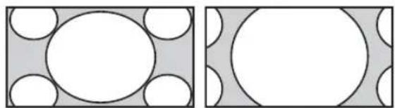
natural_image
Two geometric diagrams showing circles inscribed within rectangles, no text or symbols present4:3
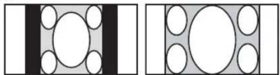
natural_image
Two abstract geometric diagrams with circles and rectangles, no text or symbols presentVoll
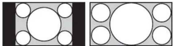
natural_image
Two geometric diagrams showing circles inside rectangles, no text or symbols presentZoom
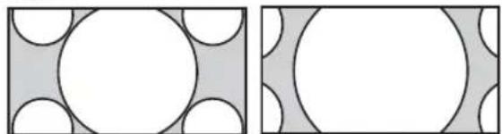
natural_image
Two abstract geometric diagrams with circles and shaded regions, no text or symbols presentHinweis
natural_image
Simple geometric diagram with a central circle surrounded by four smaller circles, enclosed in a square frame (no text or symbols)Voll 1
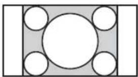
natural_image
Simple geometric diagram with a central circle surrounded by five smaller circles, no text or symbols present.Voll 2
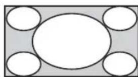
natural_image
Simple geometric diagram with five white circles arranged around a central oval (no text or symbols)Beim FWD-40LX2F/40LX2X:
Beim FWD-32LX2F/32LX2X:
S VIDEO IN Mini-DIN, 4-polig (× 1)
S VIDEO OUT Mini-DIN, 4-polig (× 1), Durchschleifung
FWD-40LX2F/40LX2X: 200 W FWD-32LX2F/32LX2X: 120 W
Abmessungen FWD-40LX2F:
988 × 591 × 125 ~mm
FWD-40LX2X:
994 × 597 × 125 ~mm
FWD-32LX2F:
796 × 486 × 107 ~mm
FWD-32LX2X:
802 × 492 × 107 ~mm
AC IN, Buchse 11, 17
H. Position 21, 26, 28
IP Address Setup 21, 31
K
Manual (IP Address Setup) 31
MENU, Taste 7, 12
Multi-Display 21, 27, 28
N
Normal 14, 26, 28
0
OPTION 1/OPTION 2, Tasten 13
OPTION 1/OPTION 2-
True Color Control 20, 23
U
Uhr einstellen 29
Uhrzeitanzeige 29
V
V. Größe 21, 26
V. Position 21, 26, 28
VIDEO IN/OUT, Anschluss 9
VIDEOEINGANGS-Adapter 9, 10
Voll 14, 25, 26
Voll 1/Voll 2 14, 28
W
natural_image
Symbol of a trash bin crossed with two crossed lines, no text or numbers presenttext_image
IN OUT RGB/COMPONENT ACTIVE THROUGH AUDIO⑨Botones ID MODE (ON/0-9/SET/C/OFF)
natural_image
Diagram showing a rectangular block with five circular holes and a central circle, with a downward arrow indicating direction (no text or symbols)Acerc.
Panorám.
natural_image
Simple geometric diagram with a central circle surrounded by four smaller circles, no text or symbols present.4:3

natural_image
Simple geometric diagram with a central circle surrounded by four smaller circles, no text or symbols present.Completa
natural_image
Simple geometric diagram with a central oval and four surrounding circles, no text or symbols present.Acercamiento
natural_image
Geometric diagram with a central circle surrounded by four semicircles on a gray background (no text or symbols)Fuente original 16:9
natural_image
Diagram showing two states of a transformation: left panel with circles inside a rectangle, right panel with circles inside a larger rectangle, both without any text or symbols.Acerc. Panorám.
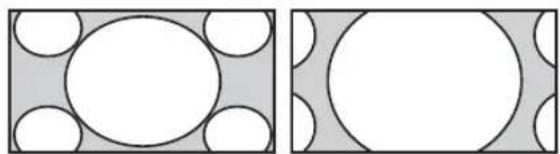
natural_image
Two geometric diagrams showing circles inscribed within rectangles, no text or symbols present4:3
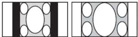
natural_image
Two abstract geometric diagrams with circles and rectangles, no text or symbols presentCompleta
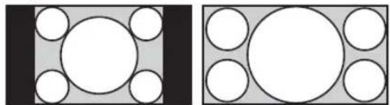
natural_image
Two geometric diagrams showing circles inside rectangles, no text or symbols presentAcercamiento

natural_image
Two abstract geometric patterns: one with white circles on a gray background, the other with white circles on a gray background (no text or symbols)Nota
natural_image
Simple geometric diagram with a central circle surrounded by four smaller circles, enclosed in a square frame (no text or symbols)Completa 1

natural_image
Geometric diagram with a central circle surrounded by five smaller circles, no text or symbols present.Completa 2
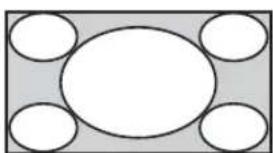
natural_image
Simple diagram with five white circles arranged around a central oval, no text or symbols present.natural_image
Pure electrical circuit lines without any symbolsnatural_image
Pure mechanical assembly diagram without any text, numbers, or symbols
natural_image
Technical line drawing of a mechanical component with grooved texture (no text or symbols)Uso de los ajustes
CONTROL S IN/OUT Minitoma (× 2)
Generales
Dimensiones FWD-40LX2F:
$$ 9 8 8 \times 5 9 1 \times 1 2 5 \mathrm{mm} $$
$$ \mathrm{FWD-40LX2X:} $$
$$ 9 9 4 \times 5 9 7 \times 1 2 5 \mathrm{mm} $$
$$ \mathrm{FWD-32LX2F:} $$
$$ 7 9 6 \times 4 8 6 \times 1 0 7 \mathrm{mm} $$
$$ \mathrm{FWD-32LX2X:} $$
$$ 8 0 2 \times 4 9 2 \times 1 0 7 \mathrm{mm} $$
$$ (\text { an / al / prf, partes salientes excluidas }) $$
Peso FWD-40LX2F:
$$ \text { A p r o x . } 2 5, 0 \mathrm{kg} $$
$$ \mathrm{FWD-40LX2X:} $$
$$ \text { A p r o x . } 2 6, 0 \mathrm{kg} $$
$$ \mathrm{FWD-32LX2F:} $$
$$ \text { Aprox. } 1 6, 0 \mathrm{kg} $$
$$ \mathrm{FWD-32LX2X:} $$
$$ \text { A p r o x . } 1 7, 0 \mathrm{kg} $$
Ajuste de PAP 15, 21, 27, 29
Ajustes de Ajustes 21, 30
Conector AUDIO IN L/R 9
Conector CONTROL S IN/OUT 9
Conector HD15 (RGB/
COMPONENT IN) 8
Conector HDMI 1/HDMI 2 IN 9
Conector REMOTE 9
Conector S VIDEO IN/OUT 9
Conector VIDEO IN/OUT 9
Config. avanzada 21, 31
Config. reloj 30
Contraste 20, 22, 23
IP Address Setup 21, 32
L
Manual (IP Address Setup) 32
Modo ancho 14, 21, 25, 29
Modo control 31
Modo ECO 16, 21, 30
Ranura OPTION 1/OPTION 2 9, 10
Restablecer 21, 26, 29
Restablecer todo 21, 32
s
Salida altavoz 20, 24
Temp. color 20, 22, 23
Tempor. sí/no 30
Tinte 20, 22
Toma AC IN 11, 17
Toma SPEAKER 11
True Color Control 20, 23
V
Vívido 22, 23
Ventana 28
AVVERTENZA
natural_image
Symbol of a trash bin crossed with no text or numbers, representing waste sorting or restriction (no text present)text_image
IN OUT RGB/COMPONENT ACTIVE THROUGH AUDIO⑨Tasti ID MODE (ON/0-9/SET/C/OFF)
natural_image
Diagram showing two rectangular blocks with white circles inside, one decreasing and the other increasing (no text or symbols)Zoom ampio

natural_image
Two geometric diagrams showing circles and rectangles with shaded regions, no text or symbols present.4:3
natural_image
Two abstract geometric diagrams with circles and rectangles, no text or symbols presentPieno
natural_image
Two geometric diagrams showing circles inside rectangles, no text or symbols presentZoom
natural_image
Two geometric diagrams showing circles within rectangles, one with shaded regions and the other with white circles (no text or symbols)Nota
natural_image
Simple geometric diagram with a central circle surrounded by four smaller circles, enclosed in a square frame (no text or symbols)Pieno 1
natural_image
Simple geometric diagram with a central circle surrounded by six smaller circles, no text or symbols present.Pieno 2
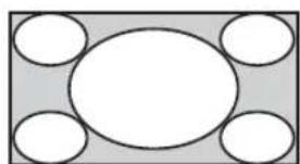
natural_image
Simple diagram with five white circles arranged around a central oval, no text or symbols present.Per FWD-40LX2F/40LX2X:
Per FWD-32LX2F/32LX2X:
text_image
Scan di base BC DE FGH FGH FGH BC DE FGHDimensioni FWD-40LX2F:
$$ 9 8 8 \times 5 9 1 \times 1 2 5 \mathrm{mm} $$
$$ \mathrm{FWD-40LX2X:} $$
$$ 9 9 4 \times 5 9 7 \times 1 2 5 \mathrm{mm} $$
$$ \mathrm{FWD-32LX2F:} $$
$$ 7 9 6 \times 4 8 6 \times 1 0 7 \mathrm{mm} $$
$$ \mathrm{FWD-32LX2X:} $$
$$ 8 0 2 \times 4 9 2 \times 1 0 7 \mathrm{mm} $$
$$ (l / a / p, \text { escluse le parti sporgenti }) $$
Peso FWD-40LX2F:
$$ \text { C i r c a } 2 5, 0 \mathrm{kg} $$
$$ \mathrm{FWD-40LX2X:} $$
$$ \text { C i r c a } 2 6, 0 \mathrm{kg} $$
$$ \mathrm{FWD-32LX2F:} $$
$$ \mathrm{Circa} 1 6, 0 \mathrm{kg} $$
$$ \mathrm{FWD-32LX2X:} $$
$$ \text { C i r c a } 1 7, 0 \mathrm{kg} $$
$$ (c - U L), F C C \text { Class } B, I C \text { Class } B, E N $$
$$ 6 0 9 5 0 - 1 (\text { N E M K O }), \text { C E }, \text { C - T i c k } $$
Display multiplo 21, 28, 29
Display ora 30
F
Fase 21, 29
Fermacavi 19
Finestra 28
Formato uscita 28
G
IP Address Setup 21, 32
L
Lingua 21, 30
Logo Sony 7, 31
Manual (IP Address Setup) 32
Mattonelle 28
Menu Audio 20, 24
Riprist. Modo audio 20, 24
Riprist. Modo imm. 20, 22, 23
Ripristina 21, 26, 29
Slot OPTION 1/OPTION 2 9, 10
Speed Setup 21, 32
Spegnimento autom. 21, 30
SRS WOW 24
Standard 22, 23, 24
Standard colore 31
T
Tasti ID MODE 13, 16
Temp. colore 20, 22, 23
Timer Sì/No 30
Tinta 20, 22
True Color Control 20, 23
U
Zoom ampio 14, 25, 26
平板宽屏监视器
警告
natural_image
Technical line drawing of a mechanical assembly with no visible text or symbols单位:cm
注
text_image
1 2 3 AUDIO OUT RGB/COMPONENT ACTIVE THROUGH①RGB/COMPONENT IN (D-sub 15 芯):
⑨ ID MODE (ON/0-9/SET/C/OFF) 键
flowchart
graph TD
    A["Hand with grid icon"] --> B["→"]
    B --> C["Wide Mode: Zoom"]
    B --> D["Wide Mode: Full"]
    B --> E["Wide Mode: 4.3"]
    C --> F["Output"]
    D --> F
    E --> F
flowchart
graph TD
    A["Hand Click"] --> B["ECO Mode: Off"]
    B --> C["ECO Mode: Low"]
    C --> D["ECO Mode: High"]
    D --> E["ECO Mode: Picture Off"]
若要取消 ECO Mode
对于 FWD-32LX2F/32LX2X:
错误 5: Primary DNS 地址错误
错误 6: Secondary DNS 地址错误
错误 7: Subnet mask 错误
Speed Setup
功率消耗 FWD-40LX2F/40LX2X:
200 W
FWD-32LX2F/32LX2X:
120 W
扬声器输出 7 W + 7 W (6 欧姆)
安全负载阻抗,6 - 16 欧姆
工作条件 温度:0 ℃ 至 35 ℃
湿度:20% 至 90%
(无湿气凝结)
UL), FCC Class B, IC Class B, EN
60950-1 (NEMKO), CE, C-Tick
设计和规格若要变更,恕不另行通知。
管脚配置
Advanced Setup (高级设定) 20, 29
All Reset (全部预设) 20, 29
Auto Adjustment (自动调节) 20, 27
Auto Shut Off (自动关闭)20, 28
Brightness (亮度) 19, 21, 22
C
CineMotion (电影) 19,21
Clock Display 28
Clock Set 28
Color System 29
Color Temp. (色温) 19, 21, 22
Color (颜色)19,21
IP Address Setup (IP 地址设定) 20, 30
L
Language (语言) 20, 28
LED 26
M
Manual (IP Address Setup) 30 MENU 键 7, 12
OPTION 1/OPTION 2 键 13
Output Format 26
P
PAP 键 12,15
PAP Setting (双画面设定)15, 20, 25, 27
PAP Size 25
Phase (相位) 20, 27
Picture (对比度) 19, 21, 22
PICTURE 键 12
Reset (初始化) 20, 25, 27
S
Sharpness (锐度) 19, 21
输入信号 32
Sony 标志 7,29
SOUND 键 12
True Color Control 19, 22
V
Vertical Shift (垂直位置调节) 20, 25, 27
Wide Zoom 14, 24, 25
Window 26
X
消音键 13
Y
遥控传感器 7
音量键 7,13
Z
支架安装挂钩 11
Zoom 14, 24