
PCSA-CXG80 - Video conferencing system SONY - Free user manual and instructions
Find the device manual for free PCSA-CXG80 SONY in PDF.

| Product type | HD video conference camera |
| Brand | Sony |
| Model | PCSA-CXG80 |
| Image sensor | CMOS 2,000,000 effective pixels |
| Video format | 1080i/59.94, 1080i/50 |
| Lens | 10× optical zoom (40× digital), f=3.4-33.9 mm, F1.8-F2.1 |
| Horizontal view angle | 8° (Tele) to 70° (Wide) |
| Minimum object distance | 100 mm (Wide) |
| Minimum illumination | 15 lux (F1.8, 50 IRE) |
| Pan movement | ±100°, max speed 300°/s |
| Tilt movement | ±25°, max speed 125°/s |
| Power supply | 19.5 V DC, 1 A max (via PCS-XG80 system) |
| Dimensions (W × H × D) | 240 × 152 × 173 mm |
| Weight | Approx. 2 kg |
| Installation angle | ≤ ±15° from horizontal |
| Operating temperature | 5 °C to 35 °C |
| Storage temperature | -20 °C to +60 °C |
| Connectors | Terminal (D-sub 15-pin), VISCA OUT (mini-DIN 8-pin) |
| Supplied accessories | Camera cable (3 m), Velcro straps (2 pairs), instruction manual, warranty certificate |
| Maintenance | Clean lens with a blower; body with soft cloth and diluted neutral detergent |
| Safety | Do not expose to rain or moisture; maintenance by qualified personnel |
| Repairability | In case of malfunction, consult an authorized Sony dealer |
| Compatibility | Exclusively with Sony PCS-XG80/XG80S HD visual communication system |
Frequently Asked Questions - PCSA-CXG80 SONY
User questions about PCSA-CXG80 SONY
0 question about this device. Answer the ones you know or ask your own.
Ask a new question about this device
Download the instructions for your Video conferencing system in PDF format for free! Find your manual PCSA-CXG80 - SONY and take your electronic device back in hand. On this page are published all the documents necessary for the use of your device. PCSA-CXG80 by SONY.
USER MANUAL PCSA-CXG80 SONY
Operating Instructions GB
Mode d'emploi FR
Printed on recycled paper.
お問い合わせは
Sony Corporation Printed in Japan
© 2008 Sony Corporation

3876297020
安全のために
後面
底面
①レンズ
光学 10 倍ズームレンズです。
natural_image
Illustration of hands operating a mechanical press or stamping device with a cross mark (no text or symbols)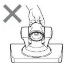
natural_image
Diagram of a hand pressing a button on a base, with a cross mark and no text or symbols present.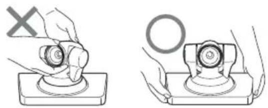
natural_image
Two technical diagrams showing hands operating a mechanical component with a cross mark and a circle symbol (no text or labels)付属の固定テープで固定する
$$ \ell = 5 \sim 7 \mathrm{mm} $$
警告
The model and serial numbers are located on the bottom. Record these numbers in the spaces provided below. Refer to these numbers whenever you call upon your Sony dealer regarding this product.
Model No. PCSA-CXG80
Serial No. ____
WARNING
To reduce the risk of fire or electric shock, do not expose this apparatus to rain or moisture.
To avoid electrical shock, do not open the cabinet. Refer servicing to qualified personnel only.
NOTICE:
This Camera Unit is an accessory and to be used exclusively with PCS-XG80/XG80S HD Visual Communication System.
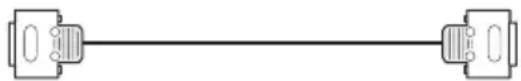
Furnished Cable
Use the following cable to connect the device in the system.
| Cable Part No. Number | ||
| Camera cable(3 m (9.8 ft)) | 1-835-441-1x 1 | |
Camera cable
natural_image
Pure diagram of two connected components without any text, numbers, or symbolsIMPORTANT
The nameplate is located on the bottom.
For customers in the U.S.A.
This device complies with Part 15 of the FCC Rules.
Operation is subject to the following two conditions: (1) This device may not cause harmful interference, and (2) this device must accept any interference received, including interference that may cause undesired operation.
This equipment has been tested and found to comply with the limits for a Class A digital device, pursuant to Part 15 of the FCC Rules. These limits are designed to provide reasonable protection against harmful interference when the equipment is operated in a commercial environment. This equipment generates, uses, and can radiate radio frequency energy and, if not installed and used in accordance with the instruction manual, may cause harmful interference to radio communications. Operation of this equipment in a residential area is likely to cause harmful interference in which case the user will be required to correct the interference at his own expense.
You are cautioned that any changes or modifications not expressly approved in this manual could void your authority to operate this equipment.
FCC Radiation Exposure Statement:
This equipment complies with FCC radiation exposure limits set forth for an uncontrolled environment. This equipment should be installed and operated with minimum distance 20 cm between the radiator & your body. This transmitter must not be co-located or operating in conjunction with any other antenna or transmitter.
For customers in Canada
This Class A digital apparatus complies with Canadian ICES-003.
IC Radiation Exposure Statement:
This equipment complies with IC RSS-102 radiation exposure limits set forth for an uncontrolled environment. This equipment should be installed and operated with minimum distance 20cm between the radiator & your body.
IC Interference Statement
This device complies with RSS-210 of the IC Rules. Operation is subject to the following two conditions:
-
This device may not cause harmful interference, and
-
This device must accept any interference received, including interference that may cause undesired operation. IC: 7424A-ZM100
For the customers in Europe
The manufacturer of this product is Sony Corporation, 1-7-1 Konan, Minato-ku, Tokyo, Japan. The Authorized Representative for EMC and product safety is Sony Deutschland GmbH, Hedelfinger Strasse 61, 70327 Stuttgart, Germany. For any service or guarantee matters please refer to the addresses given in separate service or guarantee documents.
For the customers in Europe, Australia and New Zealand
WARNING
This is a Class A product. In a domestic environment, this product may cause radio interference in which case the user may be required to take adequate measures.
In the case that interference should occur, consult your nearest authorized Sony service facility.
This apparatus shall not be used in the residential area.
CE
| Language Informal DoC | |
| Bulgarian | С настоящето Сони Корпорация декларира, че този PCSA-CXG80/ HD Camera Unit о特有的 на основните изисквания и другите съответстващи клаузи на Директива 1999/5/EC. Подробности може да намерите на Интернет страницата : http://www.compliance.sony.de/ |
| Czech | Sony Corporation tímto prohlašuje, že tento PCSA-CXG80/ HD Camera Unit je ve shodě se základními požadavky a dalšími příslušnými ustanoveními směrnice 1999/5/ES. Podrobnosti lze získat na následující URL: http://www.compliance.sony.de/ |
| Danish | Undertegnede Sony Corporation erklærer herved, at følgende udstyr PCSA-CXG80/ HD Camera Unit overholder de væsentlige krav og øvrige relevante krav i direktiv 1999/5/EF.For yderligere information gå ind på følgende hjemmeside: http://www.compliance.sony.de/ |
| Dutch | Hierbij verklaart Sony Corporation dat het toestel PCSA-CXG80/ HD Camera Unit in overeenstemming is met de essentiële eisen en de andere relevante bepalingen van richtlijn 1999/5/EG. Nadere informatie kunt u vinden op: http://www.compliance.sony.de/ |
| English | Hereby, Sony Corporation, declares that this PCSA-CXG80/ HD Camera Unit is in compliance with the essential requirements and other relevant provisions of Directive 1999/5/EC. For details, please access the following URL: http://www.compliance.sony.de/ |
| Estonian | Sony Corporation kinnitab käesolevaga seadme PCSA-CXG80/ HD Camera Unit vastavust 1999/5/EÜ direktiivi põhinõuetele ja nimetatud direktiivist tulenevatele teistele asjakohastele sätetele. Üksikasjalikum info: http://www.compliance.sony.de/. |
| Finnish | Sony Corporation vakuuttaa täten että PCSA-CXG80/ HD Camera Unit tyyppinen laite on direktiivin 1999/5/EY oleellisten vaatimusten ja sitä koskevien direktiivin muiden ehtojen mukainen. Halutessasi lisätietoja, käy osoitteessa: http://www.compliance.sony.de/ |
| French | Par la présente Sony Corporation déclare que l'appareil PCSA-CXG80/ HD Camera Unit est conforme aux exigences essentielles et aux autres dispositions pertinentes de la directive 1999/5/CE. Pour toute information complémentaire, veuillez consulter l’URL suivante: http://www.compliance.sony.de/ |
| German | Hiermit erklärt Sony Corporation, dass sich das Gerät PCSA-CXG80/ HD Camera Unit in Übereinstimmung mit den grundlegenden Anforderungen und den übrigen einschlägigen Bestimmungen der Richtlinie 1999/5/EG befindet. Weitere Informationen erhältlich unter: http://www.compliance.sony.de/ |
| Greek | Με την παρούσα η Sony Corporation δηλώνει ότι PCSA-CXG80/ HD Camera Unit συμμο ρφώνεται προς της ουσιώδεις απαιτήσεις και τις λοιπές σχετικές διατάξεις της οδηγίας 1999/5/EK. Για λεπτομέρειες παρακαλούμε όπως ελένξετε την ακόλουθη σελίδα του διαδ ικτύου: |
| Hungarian | Alulírott, Sony Corporation nyilatkozom, hogy a(z) PCSA-CXG80/ HD Camera Unit megfelel a vonatkozó alapvető követelményeknek és az 1999/5/EC irányelv egyéb előírá sainak. További információkat a következő weboldalon találhat: htt p://www.compliance.sony.de/ |
| Italian | Con la presente Sony Corporation dichiara che questo PCSA-CXG80/ HD Camera Unit è conforme ai requisiti essenziali ed alle altre disposizioni pertinenti stabilite dalla direttiva 1999/5/CE. Per ulteriori dettagli, si prega di consultare il seguente URL: http://www.compliance.sony.de/ |
| Latvian | Ar šo Sony Corporation deklarē, ka PCSA-CXG80/ HD Camera Unit atbilst Direktīvas 1999/5/EK būtiskajām prasībām un citiem ar to saistītajiem noteikumiem. Plašāka inform ācija ir pieejama: http://www.compliance.sony.de/ |
| Lithuanian | Šiuo Sony Corporation deklaruoja, kad šis PCSA-CXG80/ HD Camera Unit atitinka esminius reikalavimus ir kitas 1999/5/EB Direktyvos nuostatas. Susipažinti su visu atitikties deklaracijos turiniu Jūs galite interneto tinklalapyje: http://www.compliance.sony.de/ |
| Norwegian | Sony Corporation erklærer herved at utstyret PCSA-CXG80/ HD Camera Unit er i samsvar med de grunnleggende krav og øvrige relevante krav i direktiv 1999/5/EF. For flere detaljer, vennligst se: http://www.compliance.sony.de/ |
| Polish | Niniejszym Sony Corporation oswiadcza, .e PCSA-CXG80/ HD Camera Unit jest zgodne z zasadniczymi wymaganiami oraz innymi stosownymi postanowieniami Dyrektywy 1999/5/WE. Szczególowe informacje znalezco mo.na pod nastepujacym adresem URL: http://www.compliance.sony.de/ |
| Portuguese | Sony Corporation declara que este PCSA-CXG80/ HD Camera Unit está conforme os requisitos essenciais e outras disposições da Directiva 1999/5/ CE. Para mais informacoes, por favor consulte a seguinte URL: http://www.compliance.sony.de/ |
| Romanian | Prin prezenta, Sony Corporation declară că acest PCSA-CXG80/ HD Camera Unit respectă cerințele esențiale s,i este în conformitate cu prevederile Directivei 1995/5/EC. Pentru detalii, vă rugăm accesați următoarea adresă: http://www.compliance.sony.de/ |
| Slovak | Sony Corporation týmto vyhlasuje, že PCSA-CXG80/ HD Camera Unit splňa základné po žiadavky a všetky príslušné ustanovenia Smernice 1999/5/ES. Podrobnosti získate na nasledovnej webovej adrese: http://www.compliance.sony.de/ |
| Slovenian | Sony Corporation izjavlja, da je ta PCSA-CXG80/ HD Camera Unit v skladu z bistvenimi zahtevami in ostalimi relevantnimi določili direktive 1999/5/ES. Za podrobnosti vas napro šamo, če pogledate na URL: http://www.compliance.sony.de/ |
| Spanish | Por medio de la presente Sony Corporation declara que el PCSA-CXG80/ HD Camera Unit cumple con los requisitos esenciales y cualesquiera otras disposiciones aplicables o exigibles de la Directiva 1999/5/CE. Para mayor información, por favor consulte el siguiente URL: http://www.compliance.sony.de/ |
| Swedish | Härmed intygar Sony Corporation att denna PCSA-CXG80/ HD Camera Unit står I ö verensstämmelse med de väsentliga egenskapskrav och övriga relevanta bestämmelser som framgår av direktiv 1999/5/EG. För ytterligare information gå in på följande hemsida: http://www.compliance.sony.de/ |
For the customers in Norway
Use of this radio equipment is not allowed in the geographical area within a radius of 20 km from the centre of Ny-Ålesund, Svalbard.
For kundene i Norge
Phenomena Specific to CMOS Image
Sensors 22
Features 22
Location and Functions of Parts and
Controls 23
Installing the Camera 24
Installing the Camera on a Desk 24
Using the Supplied Hook-and-Loop Pads ....24
Attaching the Camera to a Tripod 24
Installing the Camera Using the M3 Fixing Screw Holes ......25
Troubleshooting 26
Specifications 27
Precautions
Operating or storage location
Operating or storing the camera in the following locations may cause damage to the camera:
- Extremely hot or cold places (Operating temperature: 5^ to 35^ [41°F to 95°F])
- Exposed in direct sunlight, or close to heating equipment (e.g., near heaters)
- Close to sources of strong magnetism
- Close to sources of powerful electromagnetic radiation, such as radios or TV transmitters
- Locations subject to vibration or shock
Ventilation
To prevent heat buildup, do not block air circulation around the camera.
Connection of the camera cable
Be sure to turn off the power of the HD Visual Communication System before connecting the camera to the System with the supplied camera cable. Otherwise, the camera and System may suffer damage, or the picture may not be displayed.
Transportation
When transporting the camera, repack it as originally packed at the factory or in materials equal in quality.
Cleaning the main unit
- Use a blower to remove dust from the lens or optical filter.
- When the body of the camera is dirty, clean it with a soft cloth that is soaked with a diluted neutral detergent and tightly wrung. Then finish with a dry cloth.
- Do not use any type of solvents, which may damage the finish.
- When you use a chemical cloth, follow its instructions.
- Do not sprinkle volatile matter such as pesticide over your camera nor allow rubber or vinyl to come in contact with the
camera for a long period of time. Doing so may damage the finish.
Maintenance
The camera mechanism may cause abnormal noise due to wear and lubrication loss after a long period of use. To maintain optimum performance, we recommend periodical maintenance. If abnormal noise occurs, consult with your Sony dealer.
Note on laser beams
Laser beams may damage the CMOS. If you shoot a scene that includes a laser beam, be careful not to let a laser beam become directed into the CMOS of the camera.
Phenomena Specific to CMOS Image Sensors
The following phenomena that may appear in images are specific to CMOS (Complementary Metal Oxide Semiconductor) image sensors. They do not indicate malfunctions.
White flecks
Although the CMOS image sensors are produced with high-precision technologies, fine white flecks may be generated on the screen in rare cases, caused by cosmic rays, etc. This is related to the principle of CMOS image sensors and is not a malfunction.
White flecks tend to be seen particularly in the following cases:
• during operation at a high environmental temperature
- when you have raised the gain (sensitivity)
This phenomena may be improved by turning the camera off and then on again.
Aliasing
When fine patterns, stripes, or lines are shot, they may appear jagged or flicker.
Features
The camera is designed to be used exclusively with the Sony PCS-XG80/XG80S HD Visual Communication System. The power is supplied to the camera by the HD Visual Communication System. For adjustments and settings of the camera, refer to the Operating Instructions of the PCS-XG80/XG80S.
CMOS camera with high image quality
The camera unit incorporates 2,000,000 effective picture elements (pixels) that can shoot high-definition images to offer superior picture quality.
Silent, high-speed pan and tilt action
By adopting the direct drive motor mechanism, in addition to high-speed pan/tilt action, improvement of the noise reduction mechanism lets you use the camera for a variety of purposes.
Video format compatible with full HD
The camera allows you to shoot an image using the 1080i high definition video format, which is equivalent to an HD-TV broadcast.
Location and Functions of Parts and Controls
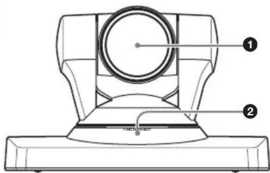
Front
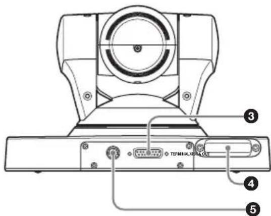
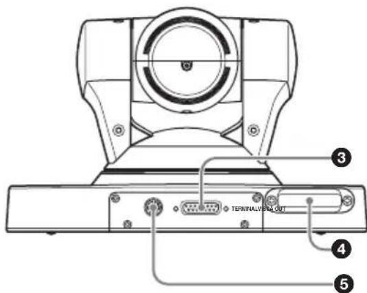
Rear
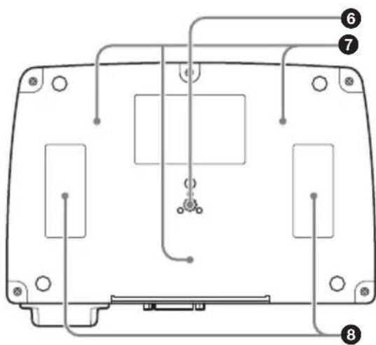
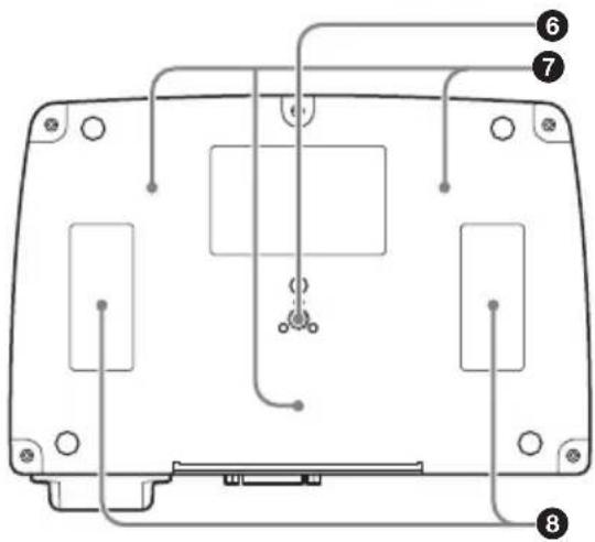
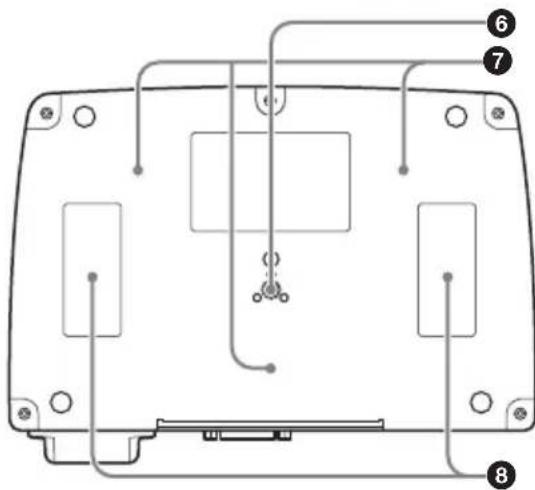
Bottom
① Lens
This is a 10-magnification optical zoom lens.
②POWER/STANDBY indicator
Lights in green when the connected HD Visual Communication System is turned on. When the Communication System is set to standby mode or is turned off, it lights in orange.
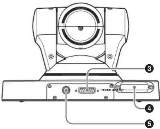
③ TERMINAL connector
Connect to the CAMERA connector on the HD Visual Communication Terminal.
④Receiver of the RF Remote Commander
Point the RF Remote Commander supplied with the HD Visual Communication System at the receiver to allow the RF Remote Commander to operate the camera. For details, refer to the Operating Instructions of the HD Visual Communication System.
⑤VISCA OUT connector
Used for VISCA communications. When a second camera is connected to the HD Visual Communication System, connect to the VISCA IN connector on the second camera.
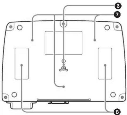
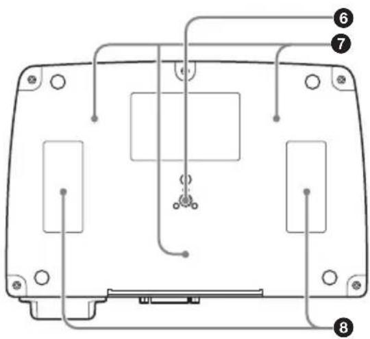
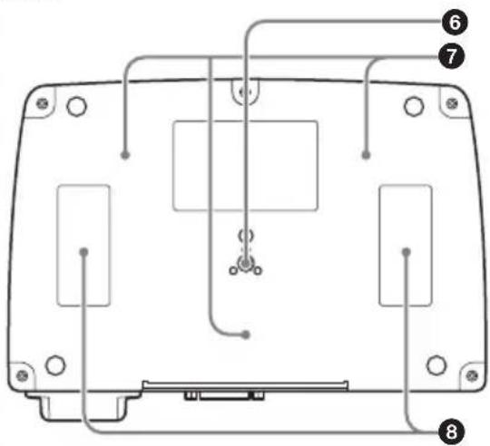
⑥Tripod attachment screw hole
Use to attach the camera to a tripod.
⑦ Fixing screw holes
Use to fix the camera to a fitting.
⑧ Attachment locations for hook-and-loop pads
When you use the supplied hook-and-loop pads, stick them to these locations.
Installing the Camera
Installing the Camera on a Desk
Place the camera on a flat surface. If you have to place the camera on an inclined surface, make sure that the inclination is less than ±15 degrees, so that the pan/tilt performance is guaranteed.
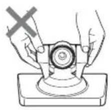
Notes
- You should take an appropriate countermeasure to prevent the camera from falling.
- Do not grasp the camera head when carrying the camera.
- Do not turn the camera head by hand. Doing so may result in a camera malfunction.
natural_image
Illustration of hands operating a mechanical component with a cross mark (no text or symbols)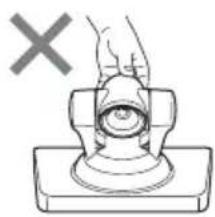
natural_image
Simple line drawing of a hand pressing a button on a base, with a 'X' symbol above (no text or labels)
natural_image
Illustration of a hand using a tool to press or install a circular component, with a 'X' symbol indicating no text or symbols on the object.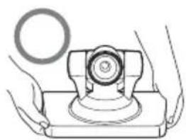
natural_image
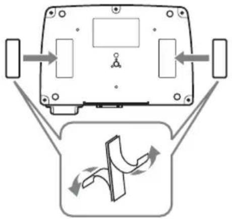
Illustration of hands operating a mechanical device with a circular component (no text or symbols)Using the Supplied Hook-and-Loop Pads
You can secure the camera to the installation location using the supplied two sets of hook-and-loop pads.
Stick the hook-and-loop pads to the attachment locations on the bottom of the camera and the other pads to the installation location, and press both sets of pads to each other until they snap together.
flowchart
graph TD
    A["Device Top Panel"] --> B["Flow Arrow"]
    B --> C["Control Panel"]
    C --> D["Arrow Right"]
    C --> E["Arrow Left"]
    C --> F["Arrow Up"]
    style A fill:#f9f,stroke:#333
    style C fill:#ccf,stroke:#333
Note
The supplied hook-and-loop pads are attached to prevent the camera from falling down or falling from an installation location. Do not use them for attaching the camera to the HD Visual Communication System. Doing so and only holding the camera may cause the Communication System to fall or result in damage to the connecting cable.
Attaching the Camera to a Tripod
Attach a tripod to the screw hole used for attaching a tripod on the bottom of the camera.
The tripod must be set up on a flat surface and its screws tightened firmly by hand. Use a tripod with screws of the following specifications.
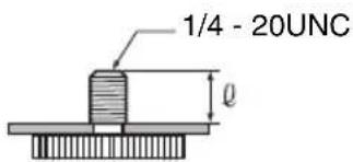
$$ \begin{array}{l} \ell = 5 - 7 \mathrm{mm} \ \ell = 7 / 3 2 - 9 / 3 2 \text { inches } \ \end{array} $$
Caution
Installation of the camera using the tripod screws and screw holes should not be done for installation on a ceiling or a shelf, etc., in a high position.
Installing the Camera Using the M3 Fixing Screw Holes
Attach the camera using 3 M3 fixing screw holes located on the bottom of the camera. Attach the camera to a fitting with a flat surface using M3 screws with the following specifications.
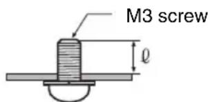
$$ \begin{array}{l} \ell = 3 - 5 \mathrm{mm} \ \ell = 1 / 8 - 7 / 3 2 \text { inches } \ \end{array} $$
Troubleshooting
Before bringing in your camera for service, check the following as a guide to troubleshooting the problem. If the problem cannot be corrected, consult with your Sony dealer.
| Symptom Cause Remedy | ||
| The power of the camera is not turned on. | The camera cable is not inserted firmly. | Insert the camera cable firmly into the TERMINAL connector on the camera. |
| The camera cable is not inserted firmly to the CAMERA connector on the HD Visual Communication System. | Insert the camera cable firmly into the CAMERA connector on the Communication System. | |
| The HD Visual Communication System cannot control the camera correctly. | — Turn off the power of the Communication System, and turn it on again after a while. | |
Specifications
Video signal 1080i/59.94, 1080i/50
Synchronization
Internal synchronization
Image device 1/3 type (6 mm), CMOS
Effective picture elements:
Approx. 2,000,000 pixels
Lens 10× (optical) (40× (digital))
f=3.4-33.9 mm, F1.8-F2.1
Horizontal angle: 8 (TELE end) to
70 degrees (WIDE end)
Minimum object distance
100 mm (4 inches) (WIDE end)
Minimum illumination
15 lux (F1.8) with 50 IRE
Pan/tilt action Horizontal: ±100 degrees
Maximum panning speed: 300
degrees/sec.
Vertical: ±25 degrees
Maximum tilting speed: 125
degrees/sec.
Input voltage 19.5 V DC
Current consumption
1 A max.
Operating temperature
5^ to 35^ (41°F to 95°F)
Storage temperature
-20^ to +60^ (-4^ to 140^)
Dimensions 240 × 152 × 173 ~mm (10 1/4 × 6 ×
6 3/4 inches) (w/h/d) (including
the feet)
Mass Approx. 2 kg (4 lb 7 oz)
Installation angle
Less than ±15 degrees to the
horizontal surface
Supplied accessories
Camera cable (3 m) (9.8 ft) (1)
Hook-and-loop pads (2 sets)
Operating Instructions (1)
Warranty booklet (1)
Design and specifications are subject to change without notice.
Note
Always verify that the unit is operating properly before use. SONY WILL NOT BE LIABLE FOR DAMAGES OF ANY KIND INCLUDING, BUT NOT LIMITED TO, COMPENSATION OR REIMBURSEMENT ON ACCOUNT OF THE LOSS OF PRESENT OR PROSPECTIVE PROFITS DUE TO FAILURE OF THIS UNIT, EITHER DURING THE WARRANTY PERIOD OR AFTER EXPIRATION OF THE WARRANTY, OR FOR ANY OTHER REASON WHATSOEVER.
Pin assignments
VISCA OUT connector (mini DIN 8-pin, female)

VISCA OUT
| Pin No. Function | |
| 1 DTR OUT | |
| 2 DSR OUT | |
| 3 TXD OUT | |
| 4 | GND |
| 5 RXD OUT | |
| 6 | GND |
| 7 No connection | |
| 8 No Connection | |
TERMINAL connector (D-sub, 15-pin)
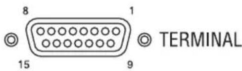
| Pin No. Function | |
| 1 Y-OUT | |
| 2 Y-GND | |
| 3 Pb-OUT | |
| 4 Pb-GND | |
| 5 | P r - |
| 6 Pb-GND | |
| 7 No connection | |
| 8 No Connection | |
| 9 +19.5 V | |
| 10 LVDS-TxD+ | |
| 11 LVDS-TxD- | |
| 12 No connection | |
| 13 LVDX-RXD+ | |
| 14 LVDS-RxD- | |
| 15 GND | |
C A M
AVERTISSEMENT
①Objectif
natural_image
Diagram of a device rear view with directional arrows indicating flow or movement, and a schematic diagram below showing a curved arrow (no text or symbols)Remarques
1/3 type (6 mm), CMOS
Unterseite
①Objektiv
natural_image
Illustration of hands operating a mechanical device with a cross mark, no text or symbols present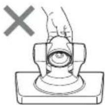
natural_image
Simple line drawing of a hand pressing a button on a base, with a 'X' mark above (no text or symbols)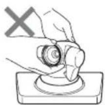
natural_image
Illustration of a hand using a circular tool to press or install a component, with a 'X' symbol above (no text or labels)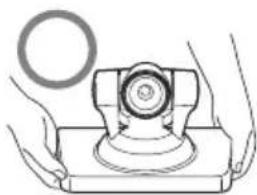
natural_image
Illustration of hands operating a mechanical device with a circular component (no text or symbols)natural_image
Diagram of a device rear view with directional arrows indicating flow or movement, and a schematic diagram below showing a curved arrow (no text or symbols)Hinweise
Videosignal 1080i/59.94, 1080i/50
Synchronisation
Interne Synchronisation
①Objetivo
natural_image
Illustration of hands operating a mechanical device with a cross mark (no text or symbols)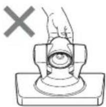
natural_image
Simple line drawing of a hand pressing a button on a base, with a cross mark above (no text or symbols)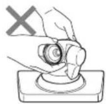
natural_image
Illustration of a hand pressing a button on a base, with a 'X' symbol in the corner (no text or symbols on the diagram itself)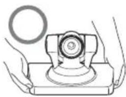
natural_image
Illustration of hands operating a mechanical device with a circular component (no text or symbols)natural_image
Diagram of a device rear view with directional arrows indicating flow or movement, and a schematic diagram below showing a curved arrow (no text or symbols)Notas
1080i/59.94, 1080i/50
Sincronización
tipo 1/3 (6 mm), CMOS
Base
①Obiettivo
natural_image
Illustration of hands operating a mechanical device with a cross mark, no text or symbols present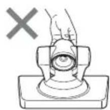
natural_image
Diagram of a hand pressing a button on a base, with a cross mark indicating no text or symbols
natural_image
Illustration of a hand holding a circular object on a base, with a 'X' symbol in the corner (no text or symbols on the object itself)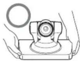
natural_image
Illustration of hands holding a mechanical component with a circular inset (no text or symbols)natural_image
Diagram of a device rear view with directional arrows and a schematic diagram below showing a curved flow path (no text or symbols)Note
1080i/59,94, 1080i/50
Sincronizzazione
Tipo 1/3 (6 mm), CMOS
massima: 125 gradi/sec.
底面
①镜头
这是一个 10 倍光学变焦镜头。
②POWER/STANDBY 指示灯
natural_image
Illustration of hands operating a mechanical device with a cross mark (no text or symbols)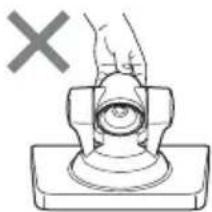
natural_image
Simple line drawing of a hand pressing a button on a base, with a gray 'X' symbol above (no text or labels)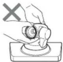
natural_image
Hand holding a circular object with a cross mark and a base, no text or symbols present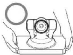
natural_image
Illustration of hands operating a mechanical device with a circular inset showing a ring (no text or symbols)使用附带的尼龙搭扣垫
natural_image
Diagram of a device rear view with directional arrows indicating movement, and a schematic diagram below showing curved flow paths (no text or symbols)注意
Parte de trás
Fundo
①Lente
4 Receptor do RF Remote Commander (controle remoto RF)
natural_image
Illustration of hands operating a mechanical device with a cross mark (no text or symbols)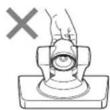
natural_image
Diagram of a hand pressing a button on a mechanical component (no text or symbols)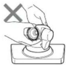
natural_image
Illustration of a hand holding a circular object on a base, with a 'X' symbol in the corner (no text or symbols on the object itself)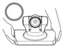
natural_image
Illustration of hands operating a mechanical device with a circular component (no text or symbols)natural_image
Diagram of a device rear view with directional arrows indicating flow or movement, and a schematic diagram below showing a curved arrow (no text or symbols)Notas
1080i/59,94, 1080i/50
Sincronização
tipo 1/3 (6 mm), CMOS
Pixels reais: Aprox. 2.000.000 de pixels

