
CBK-3610XS - Photo accessory SONY - Free user manual and instructions
Find the device manual for free CBK-3610XS SONY in PDF.
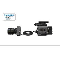


| Product type | Imager extension kit |
| Brand | Sony |
| Model | CBK-3610XS |
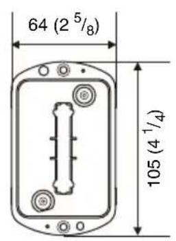
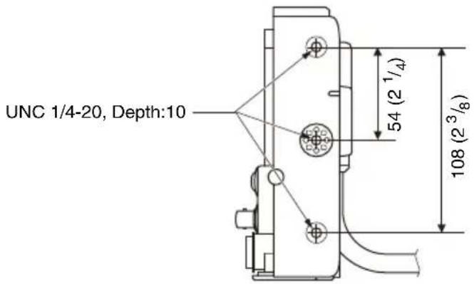
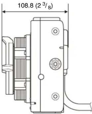
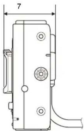
| External dimensions | See back of manual |
| Weight (CBK-3610XS complete) | Approx. 2.9 kg (6 lb 6.3 oz) |
| Weight of imager block (PL) | Approx. 1.9 kg (4 lb 3.0 oz) |
| Weight of imager block (E) | Approx. 1.4 kg (3 lb 1.4 oz) |
| Power consumption (2.7 m extension) | Approx. 2.4 W |
| Power consumption (5.5 m extension) | Approx. 3.9 W |
| Operating temperature | 0 °C to 40 °C (32 °F to 104 °F) |
| Storage temperature | -20 °C to +60 °C (-4 °F to +140 °F) |
| Maximum extension length | Approx. 5.5 m (18 ft) |
| Input connectors | 24 V IN (Fischer 3-pin), MONITOR IN (BNC) |
| Output connectors | 24 V OUT (Fischer 3-pin), MONITOR OUT (BNC) |
| External power supply | 24 V DC via Fischer 3-pin connector |
| Main function | Extends imager block up to 5.5 m without degradation |
| Camera compatibility | MPC-3610 with software V3.00 or later |
| Cleaning | Soft dry cloth; avoid alcohol, solvents, air blower |
| Precautions | Avoid condensation; turn off power before handling |
| Supplied accessories | 4 imager block fixing screws, instruction manual, warranty |
| Maintenance | Inspection before shooting; capacitor lifespan ~5 years |
Frequently Asked Questions - CBK-3610XS SONY
User questions about CBK-3610XS SONY
0 question about this device. Answer the ones you know or ask your own.
Ask a new question about this device
Download the instructions for your Photo accessory in PDF format for free! Find your manual CBK-3610XS - SONY and take your electronic device back in hand. On this page are published all the documents necessary for the use of your device. CBK-3610XS by SONY.
USER MANUAL CBK-3610XS SONY
Camera Body Adapter
Caution
Before operating the unit, please read this manual thoroughly and retain it for future reference.
For the customers in the U.S.A.
This equipment has been tested and found to comply with the limits for a Class A digital device, pursuant to part 15 of the FCC Rules. These limits are designed to provide reasonable protection against harmful interference when the equipment is operated in a commercial environment. This equipment generates, uses and can radiate radio frequency energy and, if not installed and used in accordance with the instruction manual, may cause harmful interference to radio communications. Operation of this equipment in a residential area is likely to cause harmful interference in which case the user will be required to correct the interference at his own expense.
You are cautioned that any changes or modifications not expressly approved in this manual could void your authority to operate this equipment.
If you have any questions about this product, you may call:
Sony Customer Information Service
Center 1-800-222-7669 or http://
www.sony.com/
Supplier's Declaration of Conformity
Trade Name : SONY
Model : CBK-3610XS
Responsible party : Sony Electronics Inc.
Address: 16535 Via
Esprillo, San
Diego, CA 92127
U.S.A.
Telephone: 858-942-2230
Number
This device complies with part 15 of the FCC Rules. Operation is subject to the following two conditions: (1) This device may not cause harmful interference, and (2) this device must accept any interference received, including interference that may cause undesired operation.
For the customers in Canada
CAN ICES-3 (A)/NMB-3(A)
For the customers in Europe
This product is intended for use in the following Electromagnetic Environments: E2 (commercial and light industrial), E3 (urban outdoors), E4 (controlled EMC environment, ex. TV studio).
WARNING
Operation of this equipment in a residential environment could cause radio interference.
For the customers in Europe
This apparatus shall not be used in the residential area.
For the customers in the U.S.A.
SONY LIMITED WARRANTY - Please visit http://www.sony.com/psa/warranty for important information and complete terms and conditions of Sony's limited warranty applicable to this product.
For the customers in Canada
SONY LIMITED WARRANTY - Please visit http://www.sonybiz.ca/pro/lang/en/ca/article/resources-warranty for important information and complete terms and conditions of Sony's limited warranty applicable to this product.
For the customers in Europe
Sony Professional Solutions Europe - Standard Warranty and Exceptions on Standard Warranty. Please visit http://www.pro.sony.eu/warranty for important information and complete terms and conditions.
For the customers in Korea
SONY LIMITED WARRANTY - Please visit http://bpeng.sony.co.kr/ handler/BPAS-Start for important information and complete terms and conditions of Sony's limited warranty applicable to this product.
Usage Precautions Features
- The MPC-3610 must be updated to software version V3.00 or later to use this unit. In V1.xx/V2.xx, the imager block capture data may become corrupted and an “E91-678” error displayed, indicating the unit is not operating properly. Disconnect the unit and reassemble the camera to its normal state before updating.
- The start up time may take longer when starting for the first time after replacing the imager block. Do not turn the unit off until start up has finished.
- The maximum extension length for use is approximately 5.5 m (18 ft). Operation and performance is not guaranteed if the extension is longer than the maximum length.
- If the unit is suddenly taken from a cold to a warm location, or if ambient temperature suddenly rises, moisture may form on the outer surface of the unit and/or inside of the unit. This is known as condensation. If condensation occurs, turn off the unit and wait until the condensation clears before operating the unit. Operating the unit while condensation is present may damage the unit.
- The life expectancy of the electrolytic capacitor is about 5 years under normal operating temperatures and normal usage (8 hours per day; 25 days per month). If usage exceeds the above normal usage frequency, the life expectancy may be reduced correspondingly.
The CBK-3610XS is an imager extension kit that can be connected to an MPC-3610 (option). The extension can be used in various shooting situations without degrading the performance of the imager.
• Extension up to 5.5 m (18 ft)
The CBK-3610XS attaches between the MPC-3610 and the imager block to extend the block by approximately 2.7 m (9.8 ft) or 5.5 m (18 ft).
• Supports connection to monitor and other external devices
In addition to the imager signal, it relays a monitor signal for connection with an external monitor connected to the imager block, and relays 24 V power which can be used to power a lens servo.
Location and Function of Parts
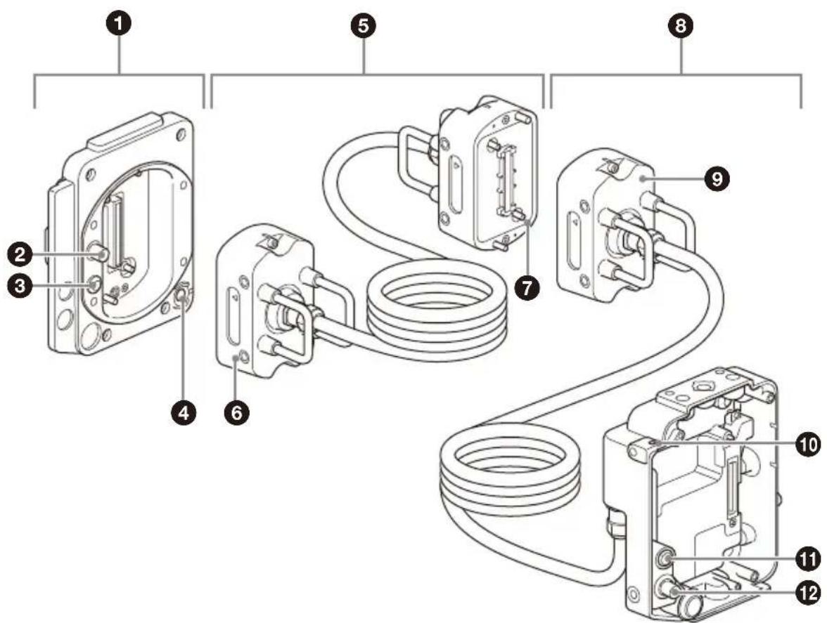
①Camera body adapter
Adapter that attaches to the camera body to extend the imager block.
②MONITOR IN connector (BNC type)
Connector that inputs the relayed monitor signal to the imager block adapter.
③24 V IN connector (Fischer 3-pin)
DC power supply input connector that supplies the external power supply to the imager block adapter.
④ASSIGN (assignable) button 3
Toggles the assigned function between on/off (enable/disable) or activates the function with each press.
For details about function assignment, refer to the MPC-3610 Operating Instructions.
Note
You can also use the ASSIGN3 button on the imager block when it is extended. However, the ASSIGN3 lamp does not light.
⑤ Extension cable
Extension cable for extending the imager block to 5.5 m (18 ft).
⑥ Receiver
Receiver adapter that connects to the camera body adapter.
⑦ Repeater
Repeater that connects to the imager block adapter receiver.
⑧ Imager block adapter
Adapter (with extension cable) that attaches to the imager block removed from the camera.
⑨ Receiver
Receiver adapter that connects to the camera body adapter or an extension cable repeater.
⑩ Tape measure hook attachment hole
Hole for attaching a tape measure hook.
You can remove the tape measure hook from the camera and attach it here.
1124 V OUT connector (Fischer 3-pin)
External power supply output connector.
It outputs the power supply connected to the 24 V IN connector of the camera body adapter.
It can be connected as an external power supply for a monitor or lens servo. It can also be used to input a REC Trigger signal.
Note
For details about Fischer 3-pin connector specifications, refer to the MPC-3610 Operating Instructions.
⑫ MONITOR OUT connector (BNC type)
Monitor signal output connector. Outputs the video signal connected to the MONITOR IN connector of the camera body adapter.
Note
For details about accessory mounting holes, see the external dimensions drawing at the back of this document.
Attaching to the Camera
Notes
- The camera must be updated to software version V3.00 or later to use this unit.
Disconnect the unit and reassemble the camera to its normal state before updating.
- Turn off the camera and wait 30 minutes or longer to allow it to cool sufficiently before attaching/removing the unit.
Perform the operation quickly in a dust-free location to prevent dust and other matter from entering the camera and adapters.
• Take care not to damage the connectors and parts. - A data transfer error may occur if there is any dust or other matter adhering to the adapter connectors. If this occurs, clean the connector using a cotton swab or similar tool.
1 Remove the four hex screws on the bottom and remove the bottom plate (①), then remove the four hex screws on the front and remove the imager block from the camera body (②).
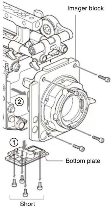
Note
Orient the lens side face down when placing the removed imager block on a flat surface. If the heat sink side is placed face down, the flangeback (flange focal distance) may be adversely affected.
2 Attach the imager block, removed in step 1, to the imager block adapter.
Align and attach using the four supplied hex screws, and tighten using a hex wrench (tightening torque of 1.4 N·m).
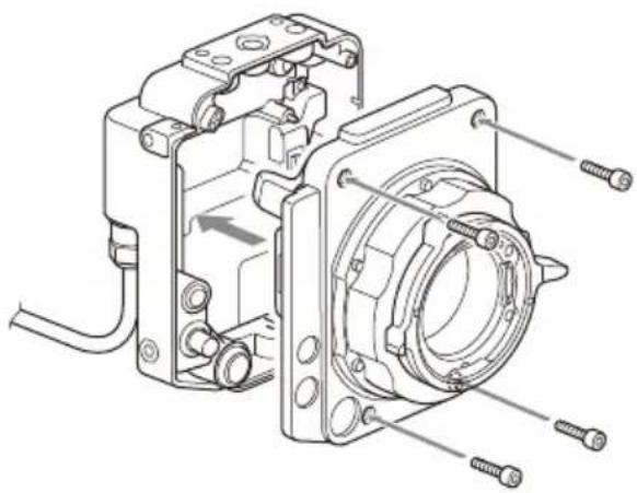
3 Attach the camera body adapter (①) and then attach the bottom plate (②).
Align and attach using the eight hex screws, removed in step 1, and tighten using a hex wrench (tightening torque of 1.4 N·m).
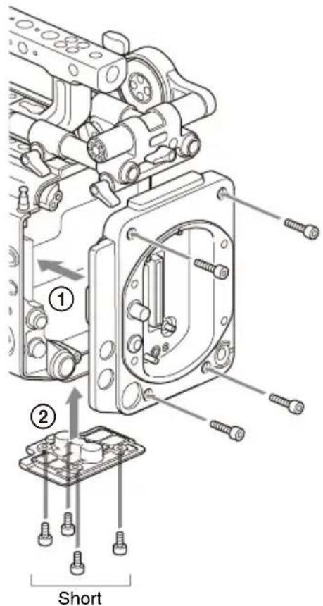
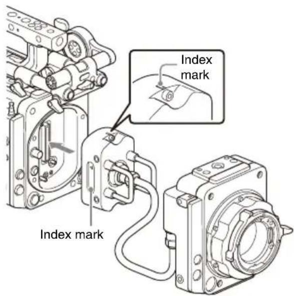
4 Attach the imager block adapter receiver to the camera body adapter.
Align with the index marks on the top and sides of the receiver, and attach using the two hex screws, and tighten using a hex wrench (tightening torque of 1.4 N·m).
Attaching the extension cable
Attach the imager block adapter receiver to the extension cable repeater (①), and attach the extension cable receiver to the camera body adapter (②) (tightening torque of 1.4 N·m).
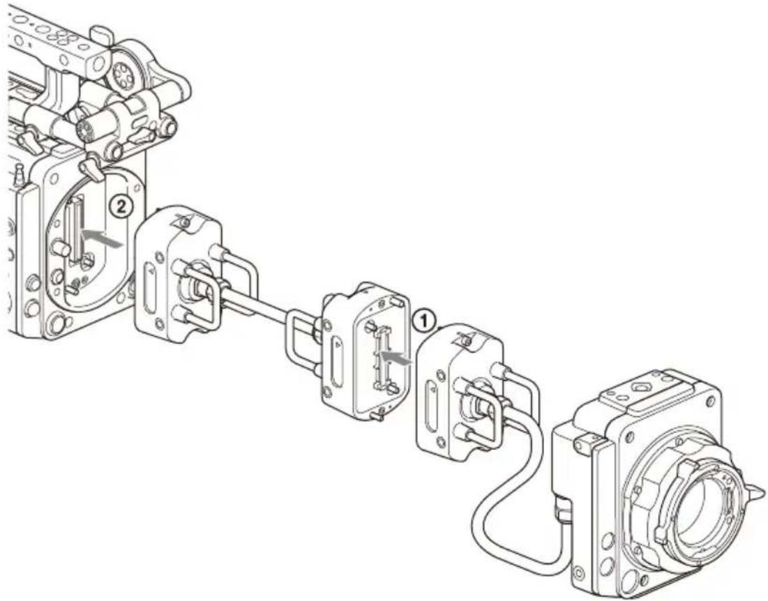
Note
When attaching the receiver, align the index marks on the top and sides of the receiver.
Removing from Camera
1 Remove the receiver from the camera body adapter. 2 Remove the camera body adapter from the camera body. 3 Remove the imager block from the imager block adapter.
Note
Orient the lens side face down when placing the removed imager block on a flat surface. If the heat sink side is placed face down, the flangeback (flange focal distance) may be adversely affected.
4 Attach the imager block, removed in step 3, to the camera body (tightening torque of 1.4 N·m).
Inspection and Maintenance
Inspection before shooting
Inspect the unit before shooting to make sure that the system is operating normally.
Cleaning
Wipe off dirt on the exterior and any metallic powder created by attachment/removal using a soft, dry cloth. In extreme cases, use a cloth moistened in a little neutral detergent, then wipe dry.
Do not use organic solvents, such as alcohol or thinners, as these may cause discoloration or other damage to the finish of the unit.
Do not clean the unit with an air blower. Dust and other particles suspended in the air may enter the unit and cause a malfunction. Also, refrain from cleaning with high air pressure equipment, such as an air duster, as these may damage optical components.
Notes on Device Connections
- A Sony audio wireless receiver cannot be used for connecting the CBK-3610XS.
- For E mount lenses, refer to the recommended lenses described in the MPC-3610 Operating Instructions. However, this is not a guarantee of operation with the recommended lenses.
Specifications
General
Power consumption
Approx. 2.4 W (with 2.7 m extension)
Approx. 3.9 W (with 5.5 m extension)
Operating temperature
0 °C to 40 °C (32 °F to 104 °F)
Storage temperature
-20 °C to +60 °C (-4 °F to +140 °F)
External dimensions
Refer to the back of this document.
Mass
CBK-3610XS
Approx. 2.9 kg (6 lb 6.3 oz)
(excluding supplied accessories)
Imager block
PL: Approx. 1.9 kg (4 lb 3.0 oz)
E: Approx. 1.4 kg (3 lb 1.4 oz)
Input/output connectors
24 V IN connector (Fischer 3-pin) (1)
24 V OUT connector (Fischer 3-pin) (1)
MONITOR IN connector (BNC type) (1)
MONITOR OUT connector (BNC type) (1)
Supplied accessories
Imager block attachment screws
(7-683-423-04) (4)
Operating Instructions (1)
Warranty (1)
Design and specifications are subject to change without notice.
Notes
• Always verify that the unit is operating properly before use. SONY WILL NOT BE LIABLE FOR DAMAGES OF ANY KIND INCLUDING, BUT NOT LIMITED TO, COMPENSATION OR REIMBURSEMENT ON ACCOUNT OF THE LOSS OF PRESENT OR PROSPECTIVE PROFITS DUE TO FAILURE OF THIS UNIT, EITHER DURING THE WARRANTY PERIOD OR AFTER EXPIRATION OF THE WARRANTY, OR FOR ANY OTHER REASON WHATSOEVER.
- SONY WILL NOT BE LIABLE FOR CLAIMS OF ANY KIND MADE BY USERS OF THIS UNIT OR MADE BY THIRD PARTIES.
- SONY WILL NOT BE LIABLE FOR THE TERMINATION OR DISCONTINUATION OF ANY SERVICES RELATED TO THIS UNIT THAT MAY RESULT DUE TO CIRCUMSTANCES OF ANY KIND.
French
④ ASSIGN button (assignable) 3
Note
3 Attach the
Note
Note
⑫ MONITOR OUT connector (BNC type)
Note
① Camera body adapter
Short screw
Caution
Note
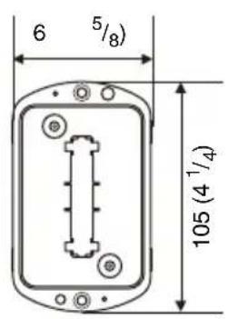
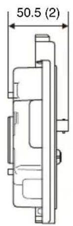
UNC 1/4-20,
Depth:10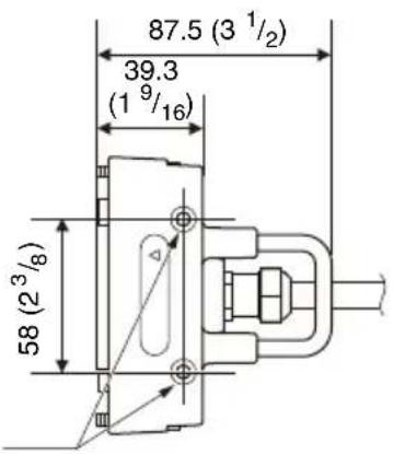
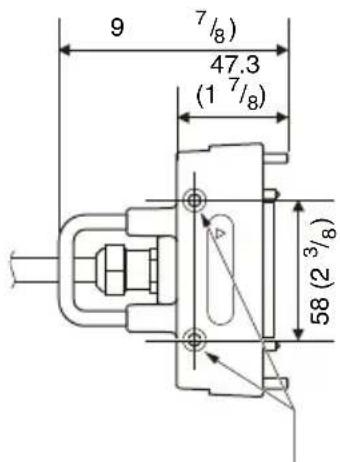
UNC 1/4-20, Depth: 10
Unit: mm (inches)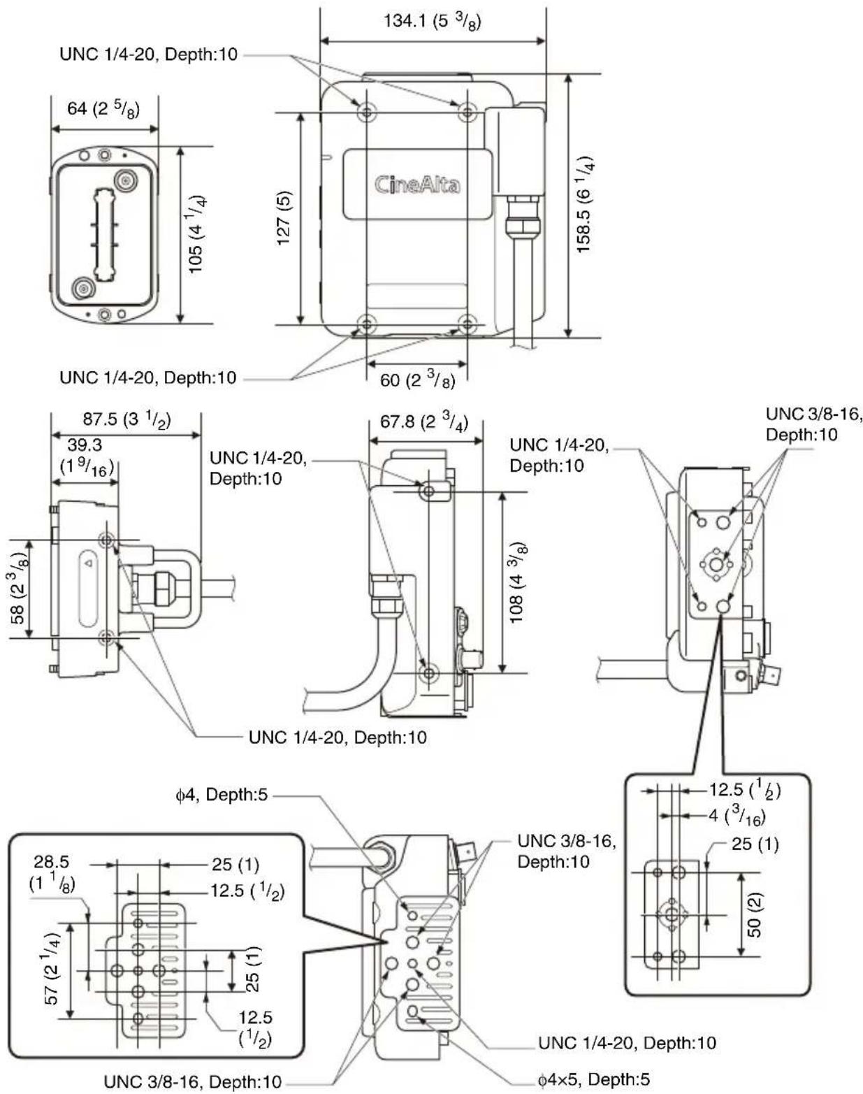
Unit: mm (inches)


- CAUTION
- FOR THE CUSTOMERS IN THE U.S.A
- SUPPLIER'S DECLARATION OF CONFORMITY
- FOR THE CUSTOMERS IN CANADA
- FOR THE CUSTOMERS IN EUROPE
- WARNING
- FOR THE CUSTOMERS IN KOREA
- USAGE PRECAUTIONS FEATURES
- EXTENSION UP TO 5.5 M (18 FT)
- SUPPORTS CONNECTION TO MONITOR AND OTHER EXTERNAL DEVICES
- LOCATION AND FUNCTION OF PARTS
- NOTE
- ⑧ IMAGER BLOCK ADAPTER
- ⑨ RECEIVER
- ⑩ TAPE MEASURE HOOK ATTACHMENT HOLE
- V OUT CONNECTOR (FISCHER 3-PIN)
- ⑫ MONITOR OUT CONNECTOR (BNC TYPE)
- ATTACHING TO THE CAMERA
- NOTES
- ATTACH THE IMAGER BLOCK, REMOVED IN STEP 1, TO THE IMAGER BLOCK ADAPTER
- ATTACH THE CAMERA BODY ADAPTER (①) AND THEN ATTACH THE BOTTOM PLATE (②)
- ATTACH THE IMAGER BLOCK ADAPTER RECEIVER TO THE CAMERA BODY ADAPTER
- ATTACHING THE EXTENSION CABLE
- REMOVING FROM CAMERA
- INSPECTION AND MAINTENANCE
- INSPECTION BEFORE SHOOTING
- CLEANING
- NOTES ON DEVICE CONNECTIONS
- SPECIFICATIONS
- GENERAL
- INPUT/OUTPUT CONNECTORS
- SUPPLIED ACCESSORIES
- FRENCH
- ATTACH THE
- ① CAMERA BODY ADAPTER
Brand : SONY
Model : CBK-3610XS
Category : Photo accessory