
CBK-VF02 - Photo accessory SONY - Free user manual and instructions
Find the device manual for free CBK-VF02 SONY in PDF.


| Product Type | External OLED Viewfinder |
| Brand | Sony |
| Model | CBK-VF02 |
| Display Technology | 0.7 inch OLED |
| Resolution | 1024 x 768 pixels |
| Magnification | 0.7x (35 mm equivalent) |
| Adjustable Diopter | -2 to +2 |
| Dimensions (W x H x D) | 60 x 42 x 99 mm |
| Weight | Approximately 170 g |
| Power Supply | Via the camcorder (multi-connector) |
| Power Consumption | Approximately 2.5 W |
| Main Features | Foldable viewfinder, color display, diopter adjustment |
| Mounting | Accessory shoe or mounting screw |
| Maintenance and Cleaning | Soft, dry cloth, avoid solvents |
| Safety | Do not expose to water, avoid shocks |
| Spare Parts and Repairability | Contact an authorized Sony service center |
| Compatibility | Sony professional camcorders (PXW, PMW series, etc.) |
Frequently Asked Questions - CBK-VF02 SONY
User questions about CBK-VF02 SONY
0 question about this device. Answer the ones you know or ask your own.
Ask a new question about this device
Download the instructions for your Photo accessory in PDF format for free! Find your manual CBK-VF02 - SONY and take your electronic device back in hand. On this page are published all the documents necessary for the use of your device. CBK-VF02 by SONY.
USER MANUAL CBK-VF02 SONY
Japanese/English/French/German/Italian/Spanish/Chinese/Russian/Kazakh
1st Edition (Revised 1)

4547747120
For safety

Turn off the camera immediately and extinguish the fire.
Meaning of warning symbols
Viewfinder front/rear position lock knob
Adjust the angle
Adjust the angle of this unit.

To flip the image/text display vertically
Diopter adjustment ring
To adjust the screen
200 cd/m² (typical)
When the eyepiece is attached
Resolution
500 or more
Color temperature
6500K (typical)
Connector
Square 26-pin connector
Supplied accessories
Operation manual (1)
Optional accessories
Viewfinder rotation and storage mechanism
BKW-401
Related products
Solid-state memory camcorder
PXW-X500, PMW-500 1)
HD color camera
HXC-D70 2)
Before operating the unit, please read this manual thoroughly and retain it for future reference.
For the customers in the U.S.A.
This equipment has been tested and found to comply with the limits for a Class B digital device, pursuant to part 15 of the FCC Rules. These limits are designed to provide reasonable protection against harmful interference in a residential installation. This equipment generates, uses and can radiate radio frequency energy and, if not installed and used in accordance with the instructions, may cause harmful interference to radio communications. However, there is no guarantee that interference will not occur in a particular installation. If this equipment does cause harmful interference to radio or television reception, which can be determined by turning the equipment off and on, the user is encouraged to try to correct the interference by one or more of the following measures:
- Reorient or relocate the receiving antenna.
- Increase the separation between the equipment and receiver.
- Connect the equipment into an outlet on a circuit different from that to which the receiver is connected.
- Consult the dealer or an experienced radio/TV technician for help.
You are cautioned that any changes or modifications not expressly approved in this manual could void your authority to operate this equipment.
This device complies with part 15 of the FCC Rules. Operation is subject to the following two conditions: (1) This device may not cause harmful interference, and (2) this device must accept any interference received, including interference that may cause undesired operation.
For the customers in Canada
CAN ICES-3 (B)/NMB-3(B)
For the customers in Europe
This product with the CE marking complies with the EMC Directive issued by the Commission of the European Community. Compliance with this directive implies conformity to the following European standards:
• EN55103-1 : Electromagnetic Interference (Emission)
• EN55103-2 : Electromagnetic Susceptibility (Immunity)
This product is intended for use in the following Electromagnetic Environments: E1 (residential), E2 (commercial and light industrial), E3 (urban outdoors), E4 (controlled EMC environment, e.g., TV studio).
For the customers in Europe
This product has been manufactured by or on behalf of Sony Corporation, 1-7-1 Konan Minato-ku Tokyo, 108-0075 Japan. Inquiries related to product compliance based on European Union legislation shall be addressed to the authorized representative, Sony Deutschland GmbH, Hedelfinger Strasse 61, 70327 Stuttgart, Germany. For any service or guarantee matters, please refer to the addresses provided in the separate service or guarantee documents.
For the customers in the U.S.A.
SONY LIMITED WARRANTY - Please visit http://www.sony.com/psa/warranty for important information and complete terms and conditions of Sony's limited warranty applicable to this product.
For the customers in Canada
SONY LIMITED WARRANTY - Please visit http://www.sonybiz.ca/solutions/Support.do for important information and complete terms and conditions of Sony's limited warranty applicable to this product.
For the customers in Europe
Sony Professional Solutions Europe - Standard Warranty and Exceptions on Standard Warranty.
Please visit
http://www.pro.sony.eu/warranty for important information and complete terms and conditions.
For the customers in Korea
SONY LIMITED WARRANTY - Please visit http://bpeng.sony.co.kr/handler/BPAS-Start for important information and complete terms and conditions of Sony's limited warranty applicable to this product.
Table of Contents
Overview.... 17
Usage Notes...... 17
Names and Functions of Parts.... 18
Attaching the Viewfinder to a Camera.... 19
Adjusting the Position.... 20
Adjusting the Angle 20
Adjusting the Focus and Image Display 21
Raising the Viewfinder Barrel and Eyepiece 21
Cleaning the LCD Screen and Interior.... 23
Specifications.... 23
Overview Usage Notes
The CBK-VF02 is a 3.5-inch LCD color viewfinder.
This viewfinder has the following features:
High resolution and wide visual angle
The viewfinder features a high-resolution LCD, for a horizontal resolution of 500 TV lines or more.
The large LCD screen allows you to shoot with ease when the eyepiece is unattached.
Stable picture
The LCD screen provides a stable image without distortion, regardless of screen brightness.
High-performance loupe
The 2-group 3-element lens (including aspheric lens) delivers pictures with low distortion and allows adjustment over a wide range of visibility.
Adjustable, detachable eyepiece
Raising or detaching the eyepiece allows you to shoot while viewing the viewfinder screen from a distance.
Adjustable, detachable viewfinder barrel and specially designed transflective LCD screen
Raising or detaching the viewfinder barrel allows you to work while viewing the LCD screen directly.
The transflective LCD screen allows visibility in any environment.
Place of use
When using the viewfinder in low temperature environments, dynamic resolution levels may decrease during the period immediately after you turn on the power.
Condensation
If the unit is suddenly taken from a cold to a warm location, or if ambient temperature suddenly rises, moisture may form on the outer surface of the unit and/or inside of the unit. This is known as condensation. If condensation occurs, turn off the unit and wait until the condensation clears before operating the unit. Operating the unit while condensation is present may damage the unit.
Permanently lit or flashing pixels on the LCD panel
The LCD panel fitted to this unit is manufactured with high precision technology, giving a functioning pixel ratio of at least 99.99%. Thus a very small proportion of pixels may be “stuck”, either always off (black), always on (red, green, or blue), or flashing. In addition, over a long period of use, because of the physical characteristics of the liquid crystal display, such “stuck” pixels may appear spontaneously. These problems are not a malfunction.
LCD image display
Due to the physical characteristics of LCD panels, there may be a decrease in brightness or a change in color temperature over a long period of use.
These problems are not a malfunction.
In addition, these occurrences will not affect recorded data.
If a still image is displayed continuously for an extended period, a residual image may become visible. Turn off the unit when not in use for extended periods.
Electrolytic capacitors
The life expectancy of the electrolytic capacitor is about 5 years under normal operating temperatures and normal usage (8 hours per day; 25 days per month). If usage exceeds the above normal usage frequency, the life expectancy may be reduced correspondingly.
Viewfinder lens
Do not leave the viewfinder lens facing toward a strong light source, such as sunlight.
Burnout of the LCD panel or fire may occur if the lens focuses the sunlight or other strong light source.

Names and Functions of Parts
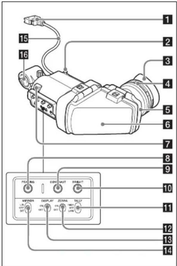
1 Plug
Connect to the VF connector (rectangular) on the camera.
2 Stopper
Prevents the viewfinder from coming off the camera when it is slid from side to side.
3 Eyecup
4 Diopter adjustment ring
Allows for optimal focus adjustment.
5 Eyepiece
Raise this up or detach this when required by the situation.
6 Viewfinder barrel
Raise this up or detach this when required by the situation.
7 Tally indicator
Lights up when recording is started by a press of the REC START button on the camera, the VTR button on the lens, or the VTR button on the remote control unit.
When an abnormality occurs, the tally indicator flashes to indicate a warning.
8 PEAKING control
Turn this control clockwise to adjust the picture sharpness and make focusing easier. This control has no effect on the output signals of the camera.
9 CONTRAST control
Adjusts the contrast of the screen. This control has no effect on the output signals of the camera.
10 BRIGHT control
Adjusts the brightness of the screen. This control has no effect on the output signals of the camera.
11 TALLY switch
Controls the tally indicator.
HIGH: The tally indicator brightness is set to high.
OFF: The tally indicator is disabled.
LOW: The tally indicator brightness is set to low.
12 ZEBRA (zebra pattern) switch
Controls the zebra pattern display as follows.
ON: Display a zebra pattern.
OFF: Do not display a zebra pattern.
13 DISPLAY switch
Turns the display of text information on and off.
ON: Display text information.
OFF: Do not display text information.
14 MIRROR switch
The image display on the screen becomes reversed horizontally or vertically when the viewfinder barrel is raised up or rotated. Use this switch to control the image display in such situations.
L/R: Reverse the image horizontally.
OFF: Do not reverse the image.
B/T: Reverse the image vertically.
15 Viewfinder cable
16 Microphone holder
Attaching the Viewfinder to a Camera
CAUTION
When the viewfinder is attached, do not leave the viewfinder lens facing toward the sun. Direct sunlight can enter through the lens, be focused in the viewfinder and cause fire.
Notes
When attaching the viewfinder, make notes of the following points.
- Be sure to power off the camera before coupling the viewfinder connector to the camera's VF connector (rectangular). If you make this connection when the camera power is on, the viewfinder may not function properly.
- Couple the viewfinder connector firmly to the camera's VF connector (rectangular). If the coupling is loose, noise may appear on the video or the tally indicator may not operate properly.
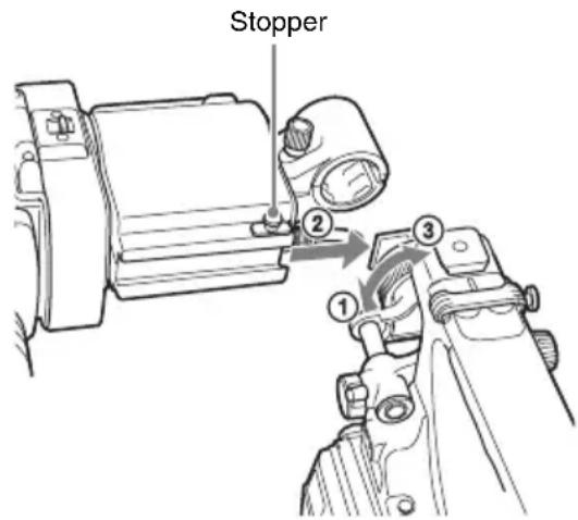
1 ① Loosen the viewfinder left-to-right positioning ring on the camera, ② attach the viewfinder to the viewfinder fitting shoe on the camera, and ③ tighten the viewfinder left-to-right positioning ring.
2 Couple the viewfinder connector to the VF connector (rectangular) on the camera.
VF connector (rectangular)
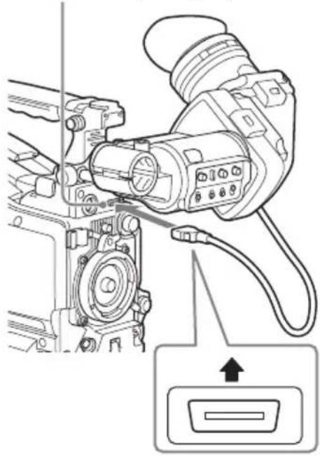
Note
Connect with the label "UPPER" facing up.
Detaching the viewfinder
You can detach the viewfinder by following the attaching procedure in reverse order, but there is an additional action to take: when detaching the viewfinder from the fitting shoe, pull up the stopper. (See the illustration in step 1.)
Adjusting the Position
To adjust the viewfinder left-to-right position, loosen the left-to-right positioning ring on the camera, and to adjust the front-to-back position, loosen the front-to-back positioning knob on the camera.
Viewfinder left-to-right positioning ring

Viewfinder front-to-back positioning knob
Adjusting the Angle
You can adjust the angle of the viewfinder.

Reversing the display (image/text indication) vertically
The viewfinder can be rotated as much as 180 degrees toward the direction facing the subject. When you do this, the picture and other information displayed in the screen appear upside down. To restore the normal display, set the MIRROR switch to B/T.
Adjusting the Focus and Image Display
Adjusting the focus
Turn the diopter adjustment ring until the image is sharpest.

Diopter adjustment ring
Adjusting the image display
Adjust the brightness, contrast, and peaking of the display with the controls shown below.
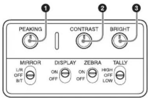
①PEAKING control ②CONTRAST control ③BRIGHT control
Raising the Viewfinder Barrel and Eyepiece
You can view the LCD screen inside the viewfinder or its mirrored image by raising up the viewfinder barrel or the eyepiece.
This section describes how to raise the viewfinder barrel and detach it. The eyepiece can also be raised and detached in the same way.
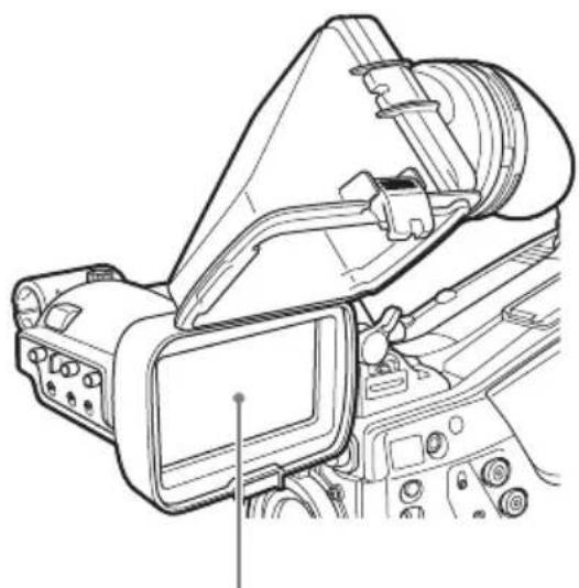
LCD screen
Raising the viewfinder barrel
Push the clip on the bottom to release and flip up the viewfinder barrel.
It locks at the 120-degree position.

Normally use it in the locked position.
Although you can open it farther from the lock position, once return it to the closed position to lock it at the 120-degree position again.
Detaching the viewfinder barrel

1 Push the clip on the bottom to release. 2 Flip up the viewfinder barrel. 3 Slide the knob on the top to the opposite side of the viewfinder barrel. 4 Detach the viewfinder barrel by horizontally sliding it.
Reversing the display (image/text indication) horizontally
By setting the MIRROR switch to L/R, you can reverse the picture and other information displayed in the screen horizontally.
Cleaning the LCD Screen and Interior
When cleaning the LCD screen or interior of the viewfinder, detach the viewfinder from the camera, detach the viewfinder barrel from the body, and take care not to damage the components.
For details on how to detach the viewfinder, see "Attaching the Viewfinder to a Camera" (page 19).
For details on how to detach the viewfinder barrel, see "Detaching the viewfinder barrel" (page 22).
To remove dust from the screen
Use a dust blower.
Note
Do not use solvents such as thinner.
After using the viewfinder in harsh environments
Check the following points after using the viewfinder in a harsh environment such as a beach, a dusty area, or a hot spring resort.
- Use an airbrush to carefully remove any dust or sand from inside the viewfinder.
- Clean the contacts of the connector.
- Check that the viewfinder is working correctly.
Specifications
General
| Power supply10.5 to 17.0 V DC (supplied by the camera) |
| Power consumption2.0 W |
| Operating temperature0 °C to 40 °C (32 °F to 104 °F) |
| Storage temperature-20 °C to +60 °C (-4 °F to +140 °F) |
| MassApprox. 680 g (1 lb 8.0 oz) |
External dimensions

LCD
3.5-inch color TFT transflective LCD Image display area dimensions
76.8 × 43.2 mm (3 1/8 × 1 3/4 inches)
(H/V, 16:9 aspect ratio)
Performance
Brightness
200 cd/m² (typical) (when eyepiece is attached)
Resolution
500 lines or more
Color temperature
6500 K (typical)
Connector
Rectangular 26-pin connector
Supplied accessories
Operation manual (1)
Optional accessories
Viewfinder Rotation Assembly
BKW-401
Related accessories
Solid-State Memory Camcorder
PXW-X500, PMW-500 1)
HD Color Camera
HXC-D70 2)
1) To attach the viewfinder to the PMW-500, the firmware version on the camcorder must be 1.10 or later. 2) To attach the viewfinder to the HXC-D70, the firmware version on the camera must be 1.21 or later.
Design and specifications are subject to change without notice.
Notes
• Always verify that the unit is operating properly before use. SONY WILL NOT BE LIABLE FOR DAMAGES OF ANY KIND INCLUDING, BUT NOT LIMITED TO, COMPENSATION OR REIMBURSEMENT ON ACCOUNT OF THE LOSS OF PRESENT OR PROSPECTIVE PROFITS DUE TO FAILURE OF THIS UNIT, EITHER DURING THE WARRANTY PERIOD OR AFTER EXPIRATION OF THE WARRANTY, OR FOR ANY OTHER REASON WHATSOEVER. - SONY WILL NOT BE LIABLE FOR CLAIMS OF ANY KIND MADE BY USERS OF THIS UNIT OR MADE BY THIRD PARTIES. - SONY WILL NOT BE LIABLE FOR THE TERMINATION OR DISCONTINUATION OF ANY SERVICES RELATED TO THIS UNIT THAT MAY RESULT DUE TO CIRCUMSTANCES OF ANY KIND.
French
Note
Note
Diopter adjustment ring
Note
Diopter adjustment ring
13 DISPLAY switch
Note
LCD screen
Note
Vertical flip display (image / text display)
Diopter adjustment ring
Adjust the image display
Usually used in the locked position.
Note
Note
The material contained in this manual consists of information that is the property of Sony Corporation and is intended solely for use by the purchasers of the equipment described in this manual.
Sony Corporation expressly prohibits the duplication of any portion of this manual or the use thereof for any purpose other than the operation or maintenance of the equipment described in this manual without the express written permission of Sony Corporation.


- FOR SAFETY
- MEANING OF WARNING SYMBOLS
- ADJUST THE ANGLE
- TO FLIP THE IMAGE/TEXT DISPLAY VERTICALLY
- TO ADJUST THE SCREEN
- RESOLUTION
- COLOR TEMPERATURE
- CONNECTOR
- SUPPLIED ACCESSORIES
- OPTIONAL ACCESSORIES
- RELATED PRODUCTS
- HD COLOR CAMERA
- FOR THE CUSTOMERS IN THE U.S.A
- FOR THE CUSTOMERS IN CANADA
- FOR THE CUSTOMERS IN EUROPE
- FOR THE CUSTOMERS IN KOREA
- TABLE OF CONTENTS
- OVERVIEW USAGE NOTES
- HIGH RESOLUTION AND WIDE VISUAL ANGLE
- STABLE PICTURE
- HIGH-PERFORMANCE LOUPE
- ADJUSTABLE, DETACHABLE EYEPIECE
- ADJUSTABLE, DETACHABLE VIEWFINDER BARREL AND SPECIALLY DESIGNED TRANSFLECTIVE LCD SCREEN
- PLACE OF USE
- CONDENSATION
- PERMANENTLY LIT OR FLASHING PIXELS ON THE LCD PANEL
- LCD IMAGE DISPLAY
- ELECTROLYTIC CAPACITORS
- VIEWFINDER LENS
- NAMES AND FUNCTIONS OF PARTS
- PLUG
- STOPPER
- EYECUP
- DIOPTER ADJUSTMENT RING
- EYEPIECE
- VIEWFINDER BARREL
- TALLY INDICATOR
- PEAKING CONTROL
- CONTRAST CONTROL
- BRIGHT CONTROL
- TALLY SWITCH
- ZEBRA (ZEBRA PATTERN) SWITCH
- DISPLAY SWITCH
- MIRROR SWITCH
- VIEWFINDER CABLE
- MICROPHONE HOLDER
- ATTACHING THE VIEWFINDER TO A CAMERA
- CAUTION
- NOTES
- COUPLE THE VIEWFINDER CONNECTOR TO THE VF CONNECTOR (RECTANGULAR) ON THE CAMERA
- NOTE
- DETACHING THE VIEWFINDER
- ADJUSTING THE POSITION
- ADJUSTING THE ANGLE
- REVERSING THE DISPLAY (IMAGE/TEXT INDICATION) VERTICALLY
- ADJUSTING THE FOCUS AND IMAGE DISPLAY
- ADJUSTING THE FOCUS
- ADJUSTING THE IMAGE DISPLAY
- RAISING THE VIEWFINDER BARREL AND EYEPIECE
- RAISING THE VIEWFINDER BARREL
- DETACHING THE VIEWFINDER BARREL
- REVERSING THE DISPLAY (IMAGE/TEXT INDICATION) HORIZONTALLY
- CLEANING THE LCD SCREEN AND INTERIOR
- TO REMOVE DUST FROM THE SCREEN
- AFTER USING THE VIEWFINDER IN HARSH ENVIRONMENTS
- SPECIFICATIONS
- LCD
- PERFORMANCE
- BRIGHTNESS
- RELATED ACCESSORIES
- FRENCH
- ADJUST THE IMAGE DISPLAY
Brand : SONY
Model : CBK-VF02
Category : Photo accessory