BKM-38H - Electronic accessory SONY - Free user manual and instructions
Find the device manual for free BKM-38H SONY in PDF.

| Brand | Sony |
| Model | BKM-38H |
| Product Type | Mounting base for monitor and control unit |
| Compatibility | BVM-E251 monitor and BKM-17R control unit |
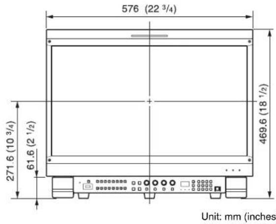
| Dimensions (W x D x H) | 576 x 271.6 x 61.6 mm |
| Included Components | Right and left bases, right and left covers, gaskets (2), feet (2), screws A (8), screws B (6), screws C (4), screws D (2), connection cable |
| Main Functions | Assemble a BVM-E251 monitor and a BKM-17R control unit |
| Installation | Requires two people; follow the steps: attach the control unit, mount the bases, connect the cable, attach the covers, then assemble the monitor |
| Power Supply | The base is not powered; the connection cable transmits DC 12V power and LAN signal between the monitor and control unit |
| Safety | Do not install near a heat source; do not step on the base; wear gloves to handle sharp edges; use only the provided screws |
| Maintenance | Clean with a soft, dry cloth; do not use solvents |
| Weight | Approximately 2.5 kg (estimated) |
| Material | Metal and plastic |
| Color | Black |
| Mounting Type | Stable table mounting |
| Connectors | DC 12V OUT and LAN (10/100) on monitor and control unit |
| Number of Included Screws | 20 screws (8 A, 6 B, 4 C, 2 D) |
| Included Accessories | DC/LAN connection cable |
| Warranty | Refer to Sony warranty terms |
Frequently Asked Questions - BKM-38H SONY
User questions about BKM-38H SONY
0 question about this device. Answer the ones you know or ask your own.
Ask a new question about this device
Download the instructions for your Electronic accessory in PDF format for free! Find your manual BKM-38H - SONY and take your electronic device back in hand. On this page are published all the documents necessary for the use of your device. BKM-38H by SONY.
USER MANUAL BKM-38H SONY
Japanese/English/French/German/Italian/Spanish
Simplified Chinese/Traditional Chinese/Korean
1st Edition (Revised 2)
安全のために
警告表示の意味
natural_image
Technical line drawing of a mechanical bracket assembly (no text or symbols)natural_image
Technical line drawing of a mechanical housing or enclosure with mounting holes and internal components (no text or symbols)ご注意
Before operating the unit, please read this manual thoroughly and retain it for future reference.
Table of Contents
Precautions 11
On Safety 11
On Installation ....11
Overview 11
Features....11
Dimensions....11
Components....11
Assembly 12
Joining the Stand and the Control Unit ....12
Joining the Stand and the Monitor....13
Note
Always verify that the unit is operating properly before use. SONY WILL NOT BE LIABLE FOR DAMAGES OF ANY KIND INCLUDING, BUT NOT LIMITED TO, COMPENSATION OR REIMBURSEMENT ON ACCOUNT OF THE LOSS OF PRESENT OR PROSPECTIVE PROFITS DUE TO FAILURE OF THIS UNIT, EITHER DURING THE WARRANTY PERIOD OR AFTER EXPIRATION OF THE WARRANTY, OR FOR ANY OTHER REASON WHATSOEVER.
Precautions
On Safety
- Do not install the attachment stand in a location near a heat source, such as a radiator or air duct, or in a place subject to excessive dust or humidity.
- Be careful not to catch your finger between the monitor and the attachment stand.
- When you assemble the attachment stand, turn off the monitor power before unplugging the cable. If you attach the attachment stand with the monitor is power on, the cable may become trapped between the monitor and the attachment stand, and this may lead to electric shock.
On Installation
- When you unpack, carry, attach or disassemble the attachment stand, do so with the help of another person, to avoid personal injury.
• Install the attachment stand on a steady table. If the attachment stand is installed on a wobbly or sloping surface, the monitor may full off and may cause personal injury. Make sure that the installation location is sufficiently strong. - The use of connecting cables other than those supplied may lead to fire and/or other damage.
• The use of screws other than those supplied may lead to injury, because they may become loose or fall out. - To carry the monitor, disconnect the connecting cables, to avoid accidents or personal injury.
- The attachment stand is designed for use with the monitor. Never use it for another purpose. If you do, it may cause personal injury.
- Be careful not to snag the power cord or connecting cord on the attachment stand, and do not step over them, which could result in disconnection or electric shock.
- Do not climb on the attachment stand or place anything heavy on it, as this may cause you to fall and injure yourself or the monitor to crash to the floor.
- If you disassemble or modify the attachment stand, it may lead to personal injury.
- Do not touch any sharp points of the attachment stand with bare hands. When you unpack, carry, attach, or disassemble the attachment stand, wear protective gloves to avoid injury.
Overview
Features
The BKM-38H Controller Attachment Stand is an attachment stand for joining a BVM-E251 and a BKM-17R Monitor Control Unit.
Joining the monitor and the control unit
The BKM-38H is for joining a monitor and a BKM-17R control unit.
Dimensions
When the unit is attached
Components
The BKM-38H consists of the components mentioned below. Make sure that you have all the components before beginning assembly.
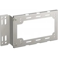
| Right stand (1) | 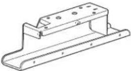 |
| Left stand (1) |  |
| Right cover (1) | 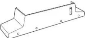 |
| Left cover (1) | 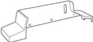 |
| Joints (2) | 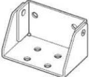 |
| Legs (2) |  |
| Screws A (3 × 8) (8) |  |
| Screws B (4 × 8) (6) |  |
| Screws C (4 × 16) (4) |  |
| Screws D (4 × 16) (2)(without flat washer) |  |
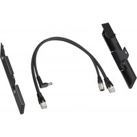
| Connecting cable (1) | 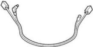 |
Assembly
Joining the Stand and the Control Unit
You can join a control unit to a monitor, using the attachment stand.
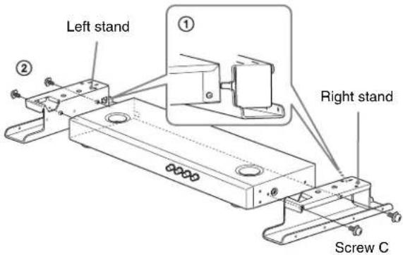
1 ①Fit the control unit into the projection of the attachment stand to join them together.
②Attach the left and right stands to the sides of the control unit, using two screws C (4 × 16) each.
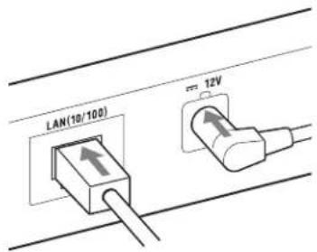
2 Connect the supplied connecting cable to the DC 12V and LAN (10/100) connectors on the rear panel of the control unit.
Note
Plug the connector of the DC cable (L-shaped) to the DC 12V connector.
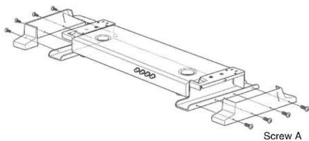
3 Attach the left and right covers to the stands, using four screws A (3 × 8) each.
natural_image
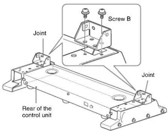
Technical line drawing of a mechanical bracket assembly with mounting holes and fasteners (no text or symbols)4 Place the joints on the left and right stands and fix them securely using two screws B (4 × 8) each.
Joining the Stand and the Monitor
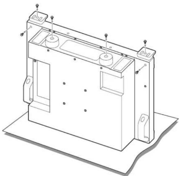
1 Turn the monitor upside down.
2 Remove the four legs from the bottom of the monitor, and remove both left and right screws from the rear of the monitor.
natural_image
Technical line drawing of a mechanical housing or enclosure with mounting brackets and internal components (no text or symbols)Note
Place the monitor flat on a soft cloth.
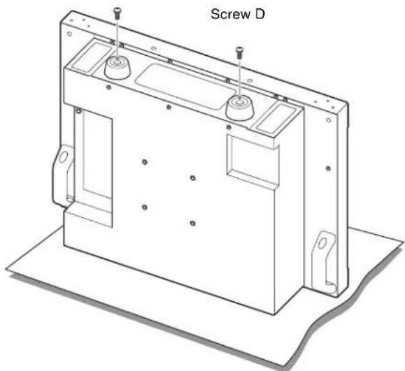
3 Attach the supplied two legs to the bottom of the monitor, using screws D (4 × 16).
natural_image
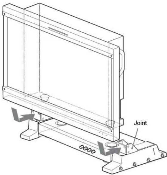
Technical line drawing of a mechanical housing component labeled 'Screw D' (no other text or symbols)4 Turn the monitor upright and place the monitor on the control unit with the stands attached.
Fit the rear of the monitor into the joints to join them together.
Note
Protect the monitor from scratches as you manipulate it around the joints.
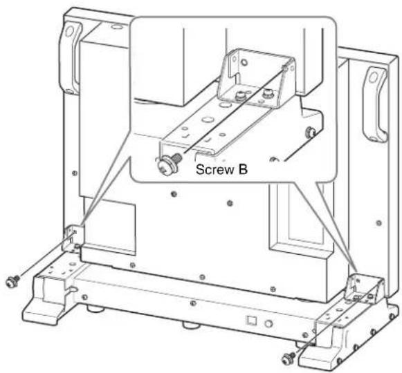
5 Secure the monitor to the stand, using two screws B (4 × 8).
Note
When you fasten screws B to secure the monitor to the stand, hold the monitor securely against the mounting surface.
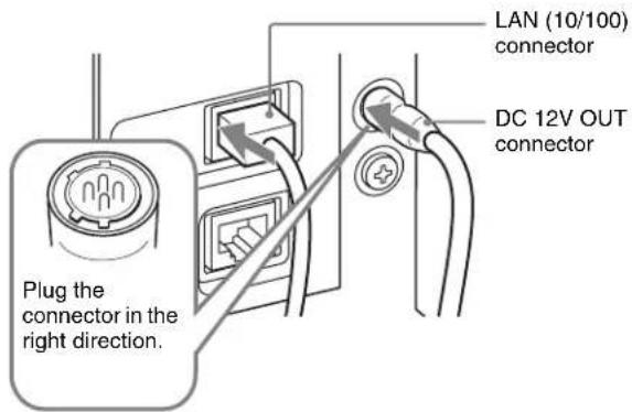
6 Plug the connecting cable into the DC 12V OUT and LAN (10/100) connectors at the side of the monitor.
Note
When connecting the cable into the DC 12V OUT connector, be sure to plug the connector of the cable into the DC 12V OUT connector on the monitor in the right direction.
Français
natural_image
Technical line drawing of a mechanical bracket assembly with mounting holes and a central hole, labeled 'Vis A' (no text or symbols on the diagram itself)natural_image
Technical line drawing of a mechanical housing or enclosure with mounting brackets and internal components (no text or symbols)Remarque
natural_image
Technical line drawing of a mechanical housing component labeled 'Vis D', showing internal components and mounting holes (no text or symbols beyond label)3
natural_image
Technical line drawing of a mechanical bracket assembly with mounting holes and fasteners (no text or symbols)4
natural_image
Technical line drawing of a mechanical housing or enclosure with mounting brackets and internal components (no text or symbols)Hinweis
natural_image
Technical line drawing of a mechanical housing component labeled 'Schraube D', showing internal compartments and mounting points (no text beyond label)natural_image
Technical line drawing of a mechanical bracket assembly (no text or symbols)natural_image
Technical line drawing of a mechanical housing or enclosure with mounting brackets and internal components (no text or symbols)Nota
natural_image
Technical line drawing of a mechanical housing or enclosure with mounting holes and internal components (no text or symbols)natural_image
Technical line drawing of a mechanical bracket assembly (no text or symbols)natural_image
Technical line drawing of a mechanical housing or enclosure with mounting holes and internal components (no text or symbols)Nota
natural_image
Technical line drawing of a Tornillo D component housing (no text or symbols on the diagram itself)4
natural_image
Technical line drawing of a mechanical housing or enclosure with mounting holes and internal compartments (no text or symbols)注意
将监视器平放在软布上。
natural_image
Technical line drawing of a mechanical housing or enclosure with mounting holes and internal components (no text or symbols)注意
將顯示器平放於軟布上。
natural_image
Technical line drawing of a mechanical assembly with mounting brackets and mounting holes (no text or symbols)natural_image
Technical line drawing of a mechanical housing or enclosure with mounting brackets and internal components (no text or symbols)참고
The material contained in this manual consists of information that is the property of Sony Corporation and is intended solely for use by the purchasers of the equipment described in this manual.
Sony Corporation expressly prohibits the duplication of any portion of this manual or the use thereof for any purpose other than the operation or maintenance of the equipment described in this manual without the express written permission of Sony Corporation.