LMD-4420 - Monitor SONY - Free user manual and instructions
Find the device manual for free LMD-4420 SONY in PDF.

User questions about LMD-4420 SONY
0 question about this device. Answer the ones you know or ask your own.
Ask a new question about this device
Download the instructions for your Monitor in PDF format for free! Find your manual LMD-4420 - SONY and take your electronic device back in hand. On this page are published all the documents necessary for the use of your device. LMD-4420 by SONY.
USER MANUAL LMD-4420 SONY
Operating Instructions GB
Mode d'emploi FR
natural_image
Diagram of a device panel with two front panels and control buttons, showing an upward arrow (no text or symbols)下部のまん中を押す。
ご注意
natural_image
Diagram of a device panel with connectors and cables, no text or symbols presentnatural_image
Technical line drawing of a mechanical assembly with connectors and a bracket (no text or symbols)2 AC アダプターを取り付ける。
natural_image
Technical line drawing of an electrical component with a lightning bolt symbol (no text or labels)AC アダプターのコードについて
次のようにまとめてください。
natural_image
Technical line drawing of a rectangular electronic device with labeled ports and connectors (no text or symbols)保証書とアフターサービス
保証書
The model and serial numbers are located at the rear. Record these number in the space provided below. Refer to these numbers whenever you call upon your Sony dealer regarding this product.
Model No. ____ Serial No. ____
To prevent fire or shock hazard, do not expose the unit to rain or moisture.
Dangerously high voltages are present inside the unit. Do not open the cabinet. Refer servicing to qualified personnel only.
In the event of a malfunction or when maintenance is necessary, consult an authorized Sony dealer.
This unit contains substances which can pollute the environment if disposed carelessly. Please contact our nearest representative office or your local environmental office in case of disposal of this unit.
Power Switch
The power switch is a functional switch only. To isolate the set from the mains supply remove the mains plug from the wall socket.
CAUTION
Danger of explosion if battery is incorrectly replaced. Replace only with the same or equivalent type recommended by the manufacturer. Dispose of used batteries according to the manufacturer's instructions.
For customers in Canada
This Class A digital apparatus complies with Canadian ICES-003.
For the customers in Europe
This product with the CE marking complies with the EMC Directive (89/336/EEC) issued by the Commission of the European Community.
Compliance with this directive implies conformity to the following European standards:
• EN55103-1: Electromagnetic Interference (Emission)
• EN55103-2: Electromagnetic Susceptibility (Immunity)
This product is intended for use in the following Electromagnetic Environment(s):
E1 (residential), E2 (commercial and light industrial), E3 (urban outdoors) and E4 (controlled EMC environment, ex. TV studio).
For the Customers in the USA
This equipment has been tested and found to comply with the limits for a Class A digital device, pursuant to Part 15 of the FCC Rules. These limits are designed to provide reasonable protection against harmful interference when the equipment is operated in a commercial environment. This equipment generates, uses, and can radiate radio frequency energy and, if not installed and used in accordance with the instruction manual, may cause harmful interference to radio communications. Operation of this equipment in a residential area is likely to cause harmful interference in which case the user will be required to correct the interference at his own expense.
You are cautioned that any changes or modifications not expressly approved in this manual could void your authority to operate this equipment.
This device complies with Part 15 of the FCC Rules. Operation is subject to the following two conditions: (1) This device may not cause harmful interference, and (2) this device must accept any interference received, including interference that may cause undesired operation.
This product contains mercury. Disposal of this product may be regulated if sold in the United States. For disposal or recycling information, please contact your local authorities or the Electronics Industries Alliance (www.ciae.org http://www.ciae.org).
Be sure to connect the AC power cord to a grounded outlet.
Warning on power connection
Use a proper power cord for your local power supply
| The United States, Canada | Continental Europe UK, Ireland, Australia, New Zealand | ||
| Plug type VM0233 | COX-07/636 | _1) | |
| Female end VM0089 | COX-02/VM0310B VM0303B | ||
| Cord type SVT H05 | VV-F CEE(13)53rd (O, C) | ||
| Rated Voltage & Current | 10A/125V | 10A/250V | 10A/250V |
| Safety approval | UL/CSA VDE | VDE | |
1) Use an appropriate rating plug which is applied to local regulations.
Attention-when the product is installed in Rack:
1. Prevention against overloading of branch circuit:
When this product is installed in a rack and is supplied power from an outlet on the rack, please make sure that the rack does not overload the supply circuit.
2. Providing protective earth:
When this product is installed in a rack and is supplied power from an outlet on the rack, please confirm that the outlet is provided with a suitable protective earth connection.
3. Internal air ambient temperature of the rack:
When this product is installed in a rack, please make sure that the internal air ambient temperature of the rack is within the specified limit of this product.
4. Prevention against achieving hazardous condition due to uneven mechanical loading:
When this product is installed in a rack, please make sure that the rack does not achieve hazardous condition due to uneven mechanical loading.
5. Install the equipment while taking the operating temperature of the equipment into consideration:
Please ensure the amount of air flow required for safe operation of this product. For the operating temperature of the equipment, refer to the specifications of the Operation Manual.
Table of Contents
Installation ....5
Cautions 5
Installing to the rack 5
Precautions ....5
On safety 5
Handling the LCD screen 5
About the fluorescent tube ....5
Maintenance 6
Disposal of the unit ....6
Features 6
Location and Function of Parts and Controls .....7
Front Panel 7
Rear 9
Power Sources ....10
Specifications ....11
About this manual
The instructions in this manual are for the following three models:
• LMD-4420 (4 type)
• LMD-5320 (5.6 type)
• LMD-7220W (7 type)
Any differences in operation are clearly indicated in the text.
Installation
Cautions
- Prevent internal heat build-up allowing adequate air circulation.
Do not place the unit on surfaces (rugs, blankets, etc.) or near materials (curtains, draperies) that may block the ventilation holes. - Do not install the unit near heat sources such as radiators or air ducts, or in a place subject to direct sunlight, excessive dust, mechanical vibration or shock.
- Do not place the monitor near equipment which generates magnetism, such as a transformer or high voltage power lines.
- Use the unit under an operating temperature of 0^ to 35^ (32°F to 95°F).
- When the unit is installed on the rack or on a shelf, leave the space above and beneath the unit and between the unit and other equipment.
- Use a fan to cool the unit if the spaces are small.
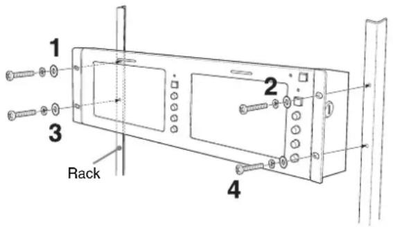
Installing to the rack
First secure the upper screws and then the lower ones, as illustrated below.
text_image
1 2 3 Rack 4Precautions
On safety
- Operate the unit on 100 - 240 V AC only.
- The nameplate indicating operating voltage, power consumption, etc. is located on the rear.
- Should any solid object or liquid fall into the cabinet, unplug the unit and have it checked by qualified personnel before operating it any further.
- Unplug the unit from the wall outlet if it is not to be used for several days or more.
- To disconnect the AC power cord, pull it out by grasping the plug. Never pull the cord itself.
- The socket-outlet shall be installed near the equipment and shall be easily accessible.
Handling the LCD screen
- Bright or dark points of lights (red, blue or green) may appear on the LCD screen. This is not a malfunction. The LCD screen is made with high-precision technology and more than 99.99% of the picture element is intact. However, some of the picture element may not appear or some of the picture element may appear constantly.
- Do not leave the LCD screen facing the sun as it can damage the LCD screen. Take care when you place the unit by a window.
- Do not push or scratch the LCD monitor's screen. Do not place a heavy object on the LCD monitor's screen. This may cause the screen to lose uniformity.
- If the unit is used in a cold place, the horizontal lines or a residual image may appear on the screen. This is not a malfunction. When the monitor becomes warm, the screen returns to normal.
- If a still picture is displayed for a long time, a residual image may appear. The residual image will eventually disappear.
- The screen and the cabinet become warm during operation. This is not a malfunction.
About the fluorescent tube
A specially designed fluorescent tube is installed as the lighting apparatus for this unit. If the LCD screen becomes dark, unstable or does not turn on, consult your Sony dealer.
Maintenance
Before cleaning
Be sure to disconnect the AC power cord from the AC outlet.
On cleaning the monitor screen
The monitor screen surface is especially treated to reduce reflection of light.
As incorrect maintenance may impair the performance of the monitor, take care with respect to the following:
- Wipe the screen gently with a soft cloth such as a cleaning cloth or glass cleaning cloth.
- Stubborn stains may be removed with a soft cloth such as a cleaning cloth or glass cleaning cloth lightly dampened with water.
- Never use solvent such as alcohol, benzene or thinner, or acid, alkaline or abrasive detergent, or chemical cleaning cloth, as they will damage the screen surface.
On cleaning the cabinet
- Clean the cabinet gently with a soft dry cloth. Stubborn stains may be removed with a cloth lightly dampened with mild detergent solution, followed by wiping with a soft dry cloth.
- Use of alcohol, benzene, thinner or insecticide may damage the finish of the cabinet or remove the indications on the cabinet. Do not use these chemicals.
- If you rub on the cabinet with a stained cloth, the cabinet may be scratched.
- If the cabinet is in contact with a rubber or vinyl resin product for a long period of time, the finish of the cabinet may deteriorate or the coating may come off.
Disposal of the unit
- Do not dispose of the unit with general waste. Do not include the monitor with household waste.
- The fluorescent tube includes mercury. Dispose of the monitor in accordance with the regulations of your local sanitation authority.
If you have any questions about this unit, contact your authorized Sony dealer.
Features
Two 7-type wide LCD panels are mounted for LMD-7220W, three 5.6-type LCD panels are mounted for LMD-5320 and four 4-type LCD panels are mounted for LMD-4420.
High brightness LCD panel
Because the monitor uses high brightness and high contrast technology, it can be used under various lighting conditions.
Rack mount monitors with tilt function
LMD-7220W and LMD-5320 are mounted to a 3U size rack and LMD-4420 is mounted to a 2U size rack. All the monitors are equipped with tilt function. They can be installed to a 19-inch standard rack. They are essential when space is at a premium in crowded OB vehicles.
Vertical arrangement of controls for easy operation and unitary layout
The controls of three models are laid out vertically and have a unitary design. When the monitor is tilted downward, it is easy to operate.
Lightweight, thin design/AC power adaptor mount function
The lightweight, thin design reduces the load for an OB vehicle and the space needed for the equipment. Also, an AC power adaptor can be installed to the rear of the monitor for easy use.
Two color system available
The monitor can display NTSC and PAL signals. The appropriate color system is selected automatically.
SDI optional input function
SDI signals can be available when input adaptor BKM-320D (optional) is attached. The adaptor can be attached to each monitor.
Energy-saving design
Because of the low power consumption LMD-7220W 23W, LMD-5320 22W and LMD-4420 18W electric power, the generation in an OB vehicle is reduced.
Remote function
The switching of an optional input (when BKM-320D is connected) and video input, tally lamp and aspect ratio (LMD-7220W only) can be controlled by an external equipment.
3-color tally lamp
The tally lamp lights in red, green or amber to monitor each input picture and check the on-air mode. The tally function can be operated with the remote function.
Aspect setting (LMD-7220W only)
You can set the monitor to 16:9 or 4:3 when a video signal is input.
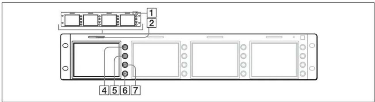
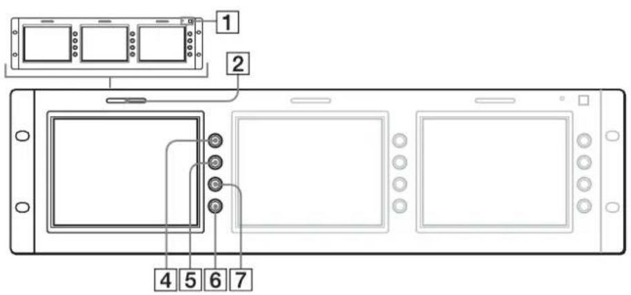
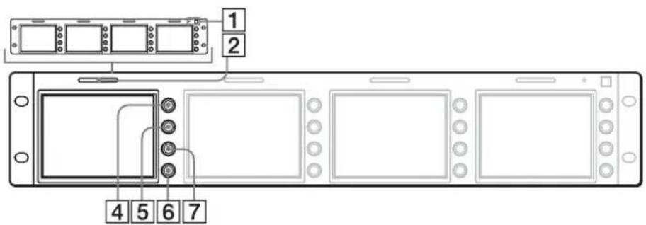
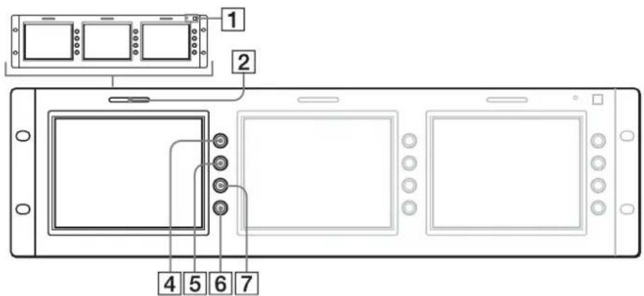
Location and Function of Parts and Controls
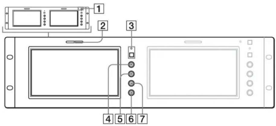
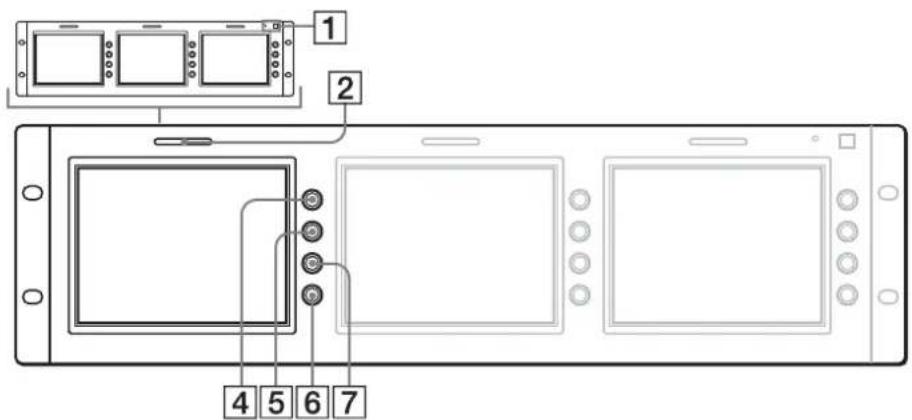
Front Panel
Each panel is equipped with buttons and controls other than the POWER switch and indicator.
LMD-7220W
text_image
Diagram of a device control panel with labeled components including display, ports, and buttonsLMD-5320
text_image
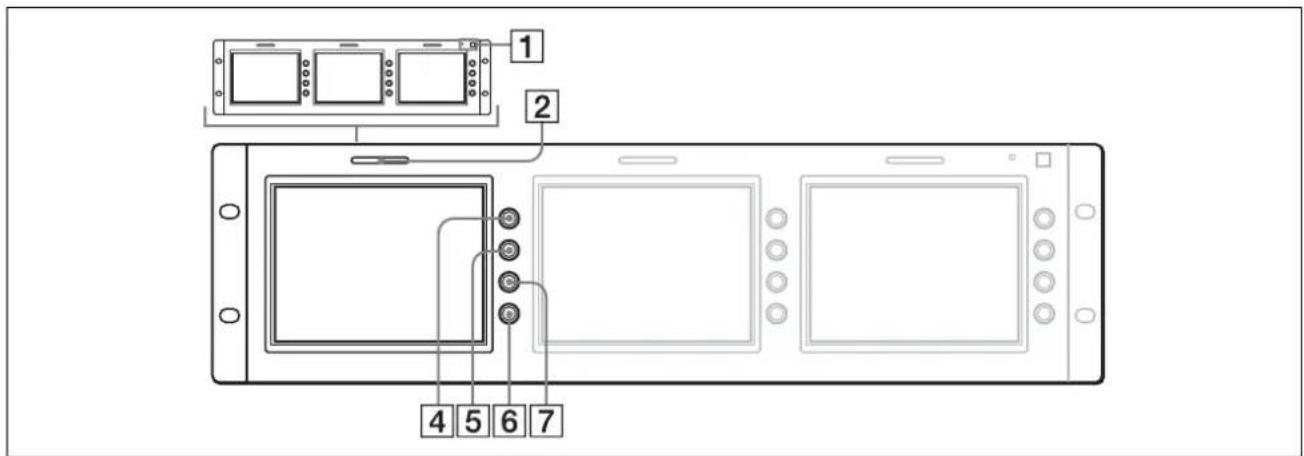
1 2 4 5 6 7LMD-4420
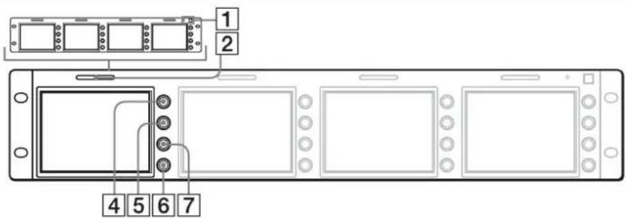
text_image
1 2 4 5 6 71 POWER switch and indicator
Each time you press the switch, the power is turned on or off. When the power is turned on, the indicator lights in green.
2 Tally lamp
You can check the status of the monitor that the signal is input by the color.
The lamp lights in red or green by signals from the equipment connected to the REMOTE connector.
When red and green signals are input, the lamp lights in amber.
The pins on the REMOTE connector are used to control the tally lamp.
For details, see page 9.
③ Aspect select button and indicator (LMD-7220W only)
Sets the aspect ratio of the picture. When the button is pressed, the aspect ratio of the picture is set to 4:3 and the indicator lights.
4 CONTRAST control
Turn this control clockwise to make the contrast higher or counterclockwise to make it lower.
5 PHASE control
This control is effective only for the NTSC color system.
Turn it clockwise to make the skin tones greenish or counterclockwise to make them purplish.
6 BRIGHT (brightness) control
Turn this control clockwise to increase the brightness or counterclockwise to decrease it.
Indistinctness of the picture when the viewing angle of the monitor is adjusted may be compensated by adjusting the brightness.
7 CHROMA control
Turn this control clockwise to increase the color intensity or counterclockwise to decrease it.
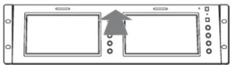
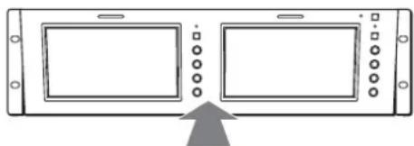
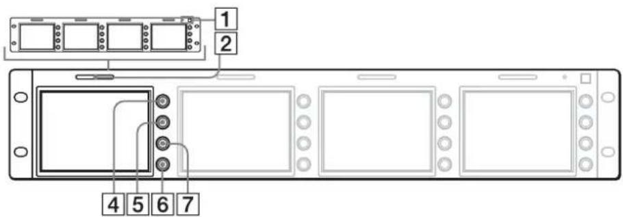
Adjusting the viewing angle
You can adjust the viewing angle of LMD-5320/7220W up to 10 degrees upward or downward and LMD-4420 up to 8 degrees upward or 10 degrees downward.
Adjusting upward
Press the center top.
natural_image
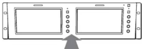
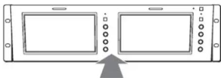
Pure diagram of a device panel with two rectangular panels and a central arrow, no text or symbols present.Adjusting downward
natural_image
Diagram of a device panel with two screens and control buttons, showing an upward arrow (no text or symbols)Press the center bottom.
NOTE
When the AC adaptor is attached to the monitor and the angle is adjusted, the AC adaptor may be touched to the equipment set to upper or lower. Remove the AC adaptor holder from the monitor.
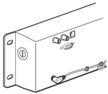
Rear
The illustration refers to LMD-4420.
Each panel is equipped with connectors other than the DC IN jack and AC adaptor attachment.

text_image
1 2 3 4 5 61 DC IN jack
Connect the supplied AC adaptor.
2 AC adaptor attachment
Attach the supplied AC adaptor.
3VIDEO IN connector (BNC)
Connect to the video output connector of the VCR, etc.
When input adaptor BKM-320D is connected to the OPTION IN connector, this connector does not function.
An optional input (OPTION) and video input (VIDEO) can be switched by using the REMOTE connector.
4VIDEO OUT connector (BNC)
Loop-through output of the VIDEO IN connector. The connector is automatically terminated at 75 ohms.
5OPTION IN connector (D-sub 9 pin, female)
When optional Sony input adaptor BKM-320D is connected, SDI signals are input.
NOTE
Do not install the other equipment than BKM-320D. It causes to damage the unit or the equipment.
6 REMOTE connector (modular)
Forms a parallel switch and controls the monitor externally. The pin assignment and factory setting function assigned to each pin are given below.
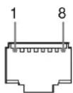
| Pin number Function (High Low) | |||
| 1 VIDEO IN (OFF ON)* | |||
| 2 OPTION IN (SDI) | (OFF ON)* | ||
| 3 | T | a | 1 |
| 4 Tally Green (OFF ON) | |||
| 5 | Ground | ||
| 6 | N.C | ||
| 7 | N.C | ||
| 8 | 16:9/4:3 Selectable | (16:9 4:3)** | |
*Functions when BKM-320D is connected. When both pins are shorted, OPTION IN (SDI) is prior to VIDEO IN.
**LMD-7220W only LMD-5320/4420: N.C
To switch each function between high and low, change pin connections in the following way.
High: Leave each pin open.
Low: Short each pin and 5-pin at the same time.
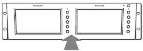
Power Sources
Connect the AC adaptor.
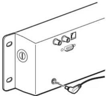
natural_image
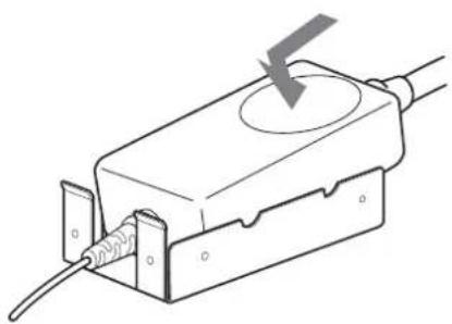
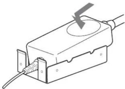
Diagram of a device panel with connectors and cables, no text or symbols presentWhen attaching the AC adaptor to the monitor
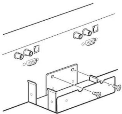
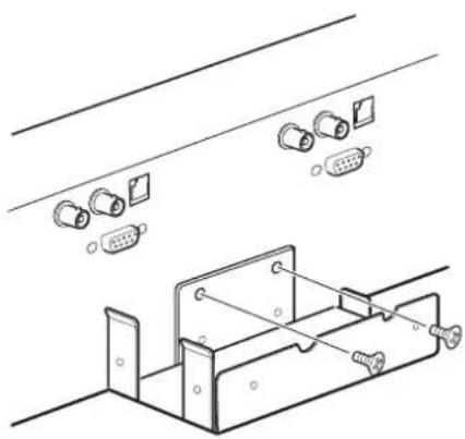
1 Install the supplied bracket to the rear of the monitor.

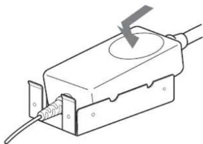
natural_image
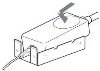
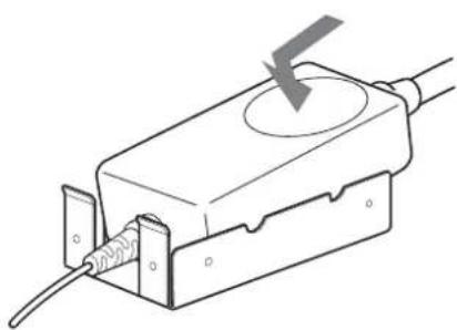
Technical line drawing of a mechanical assembly with connectors and a bracket (no text or symbols)2 Attach the AC adaptor.
natural_image
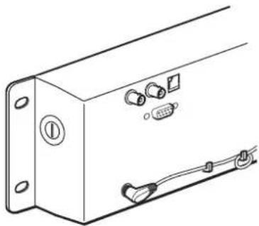
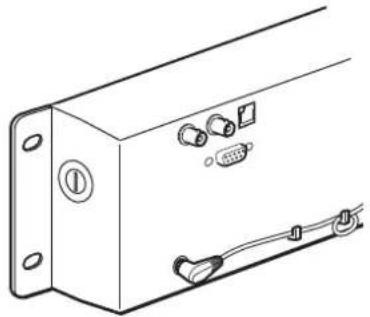
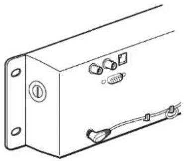
Line drawing of a mechanical component with a circular top and threaded end, showing internal wiring (no text or symbols)About the AC adaptor cord
Clamp the cord as illustrated.
natural_image
Technical line drawing of a rectangular electronic device with labeled ports and connectors (no text or symbols)Specifications
Picture performance
LMD-7220W
LCD Panel a-Si TFT Active Matrix
Picture size 7 type
154.1 × 86.6 × 176.7 mm (W/H/
Diagonal)
(6^1 / 8× 3^1 / 2× 7 inches)
Resolution 480 × 234 dots
Pixel efficiency 99.99 %
Viewing angle 40°/65°/65°/65° (typical)
(up/down/left/right contrast 10:1)
Aspect ratio 16:9
Colors Full color
LMD-5320
LCD Panel a-Si TFT Active Matrix
Picture size 5.6 type
113.3 × 84.7 × 141.5 mm (W/H/
Diagonal)
(4^1/2 × 3^3/8 × 5^5/8 inches)
Resolution 320 × 234 dots
Pixel efficiency 99.99 %
Viewing angle 50°/30°/50°/50° (typical)
(up/down/left/right contrast 10:1)
Aspect ratio 4:3
Colors Full color
LMD-4420
LCD Panel a-Si TFT Active Matrix
Picture size 4 type
82.1× 61.8× 102.8mm (W/H/
Diagonal)
(3^1/4× 2^1/2× 4^1/8 inches)
Resolution 480 × 234 dots
Pixel efficiency 99.99 %
Viewing angle 50°/30°/50°/50° (typical)
(up/down/left/right contrast 10:1)
Aspect ratio 4:3
Colors Full color
Input/output
LMD-7220W
VIDEO IN: BNC connectors (2), composite 1
Vp-p ± 2 dB, sync negative (75
ohms terminated)
OUT: BNC connectors (2), loopthrough (75 ohms terminated
automatically)
OPTION IN
D-sub 9-pin connectors (2)
REMOTE Modular connectors 8-pin (2) (See the pin assignment on page 9.)
LMD-5320
VIDEO IN: BNC connectors (3), composite 1
Vp-p ± 2 dB, sync negative (75 ohms terminated)
OUT: BNC connectors (3), loop-through (75 ohms terminated automatically)
OPTION IN
D-sub 9-pin connectors (3)
REMOTE Modular connectors 8-pin (3) (See the
See the pin assignment on page 9
LMD-4420
VIDEO IN: BNC connectors (4), composite 1
Vp-p ± 2 dB, sync negative (75 ohms terminated)
OUT: BNC connectors (4), loop-through (75 ohms terminated automatically)
OPTION IN
D-sub 9-pin connectors (4)
REMOTE Modular connectors 8-pin (4) (See the pin assignment on page 9.)
General
Power consumption
LMD-7220W
Maximum: Approx. 26W (with 2× BKM-320D)
Standard: Approx. 23W (without optional input adaptor)
LMD-5320
Maximum: Approx. 28W (with 3× BKM-320D)
Standard: Approx. 22W (without optional input adaptor)
LMD-4420
Maximum: Approx. 26W (with 4× BKM-320D)
Standard: Approx. 18W (without optional input adaptor)
Power requirement
12 V DC (with the supplied AC adaptor)
When this product is operated by AC adaptor:
Peak inrush current
LMD-7220W
(1) Power ON, current probe method: 57 A (230V)
(2) Hot switching inrush current, measured in accordance with European standard EN55103-1: 8 A (230 V)
LMD-5320
(1) Power ON, current probe method: 55 A (230V)
(2) Hot switching inrush current, measured in accordance with European standard EN55103-1:8 A (230 V)
LMD-4420
(1) Power ON, current probe method: 53 A (230V)
(2) Hot switching inrush current, measured in accordance with European standard EN55103-1:8 A (230 V)
Operating conditions
Temperature: 0 to 35^ C (32 to 95^ F)
Humidity: 30 to 85 % (No condensation)
Pressure: 700 to 1,060 hPa
Transport and storage conditions
Temperature: -10 to 40^ C (14 to 104^ F)
Humidity: 0 to 90 %
Pressure: 700 to 1,060 hPa
Dimensions (w/h/d)
LMD-7220W: Approx. 482× 133 × 47 mm (19 × 5 ^1 /4 × 1 ^7 /8 inches)
LMD-5320: Approx. 482 × 133 × 47 mm ( 19 × 5^1/4 × 1^7/8 inches)
LMD-4420: Approx. 482 × 88.1 × 47 mm ( 19 × 3^1/2 × 1^7/8 inches)
Mass LMD-7220W: Approx. 2.3 kg (5 lb 1 oz)
LMD-5320: Approx. 2.3 kg (5 lb 1 oz)
LMD-4420: Approx. 1.9 kg (4 lb 3 oz)
Accessories supplied
AC adaptor (1)
AC adaptor holder (1)
Screws for AC adaptor holder (2)
AC cord (1)
Warranty Card (1)
Operating Instructions (1)
Optional accessory
Input adaptor BKM-320D
Design and specifications are subject to change without notice
AVERTISSEMENT
Tube fluorescent ....4
Entretien 5
• LMD-7220W (Type 7)
text_image
Diagram of a device setup with labeled components including screen, monitor, and control panelLMD-5320
text_image
1 2 4 5 6 7LMD-4420
text_image
1 2 4 5 6 7natural_image
Pure diagram of a device panel with two rectangular panels and an arrow pointing to one panel (no text or symbols)Réglage vers le bas

natural_image
Diagram of a device panel with two screens and control buttons, showing an upward arrow (no text or symbols)natural_image
Diagram of a device panel with connectors and a cable, no text or symbols presentnatural_image
Technical line drawing of a mechanical assembly with connectors and mounting brackets (no text or symbols)natural_image
Line drawing of a mechanical component with a lightning bolt symbol (no text or labels)natural_image
Technical line drawing of a rectangular electronic device with labeled ports and connectors (no text or symbols)Spécifications
Performances de l'image
LMD-7220W
Tablette LCD Matrice active TFT a-Si
Format d'image
Type 7
154,1 × 86,6 × 176,7 mm (L/H/
Diagonal)
(6^1 / 8× 3^1 / 2× 7 pouces)
text_image
Diagram of a device panel with labeled components including screen, display, and control buttonsLMD-5320
text_image
1 2 4 5 6 7LMD-4420
text_image
1 2 4 5 6 7natural_image
Pure diagram of a device panel with two rectangular panels and an arrow pointing to one panel (no text or symbols)Verringerung
natural_image
Diagram of a device panel with two screens and control buttons, showing an upward arrow (no text or symbols)natural_image
Technical line drawing of a device panel with connectors and a cable (no text or symbols)natural_image
Technical line drawing of a mechanical assembly with connectors and mounting brackets (no text or symbols)natural_image
Line drawing of a mechanical component with a circular top and threaded base, showing internal wiring (no text or symbols)natural_image
Technical line drawing of a rectangular electronic device with labeled ports and connectors (no text or symbols)Spezifikationen
Bildqualität
LMD-7220W
LCD-Anzeigefeld
OUT: BNC-Anschlüsse (2),
OUT: BNC-Anschlüsse (3),
OUT: BNC-Anschlüsse (4),
LMD-5320: ca. 482 × 133 × 47 mm
(19× 5^1 / 4× 1^7 / 8 Zoll)
LMD-4420: ca. 482 × 88,1 × 47 mm
(19× 3^1 / 2× 1^7 / 8 Zoll)
Gewicht LMD-7220W: ca. 2,3 kg (5 lb 1 oz)
LMD-5320: ca. 2,3 kg (5 lb 1 oz)
LMD-4420: ca. 1,9 kg (4 lb 3 oz)
text_image
Diagram of a device control panel with labeled components including display, ports, and buttonsLMD-5320
text_image
1 2 4 5 6 7LMD-4420
text_image
1 2 4 5 6 71 Interruptor e indicador POWER
natural_image
Pure diagram of a device interface with two rectangular panels and a gray arrow pointing to one panel (no text or symbols)Ajuste hacia abajo

natural_image
Diagram of a device panel with two screens and control buttons, showing an upward arrow (no text or symbols)Presione la parte inferior central.
NOTA
4 Conector VIDEO OUT (BNC)
6 Conector REMOTE (modular)
natural_image
Diagram of a device panel with connectors and a cable, no text or symbols presentnatural_image
Technical line drawing of a mechanical assembly with connectors and mounting holes (no text or symbols)natural_image
Line drawing of a mechanical component with a screw and circular top, no text or symbols presentnatural_image
Technical line drawing of a rectangular electronic device with labeled ports and connectors (no text or symbols)Especificaciones
OUT: Conectores BNC (2),
encadenados (terminados
OUT: Conectores BNC (3),
encadenados (terminados
OUT: Conectores BNC (4),
encadenados (terminados
text_image
Diagram of a device control panel with labeled components including display, ports, and buttonsLMD-5320

text_image
1 2 4 5 6 7LMD-4420

text_image
1 2 4 5 6 7natural_image
Pure diagram of a device panel with two rectangular blocks and an upward arrow, no text or symbols present.natural_image
Diagram of a device panel with two screens and control buttons, showing an upward arrow (no text or symbols)natural_image
Diagram of a device panel with connectors and a cable, no text or symbols presentnatural_image
Technical line drawing of a mechanical assembly with connectors and mounting holes (no text or symbols)natural_image
Line drawing of a mechanical component with a screw and circular feature, no text or symbols presentnatural_image
Technical line drawing of a rectangular electronic device with labeled ports and connectors (no text or symbols)40°/65°/65°/65° (tipico)
(alto/basso/sinistra/destra contrasto 10:1)
Rapporto di formato
16:9
Colori Colore pieno
LMD-5320
Pannello LCD a-Si TFT Active Matrix
Dimensioni immagine
5,6 pollici
113,3 × 84,7 × 141,5 mm (W/H/D)
(4^1 / 2× 3^3 / 8× 5^5 / 8 pollici)
natural_image
Diagram of a device panel with two rectangular panels and a gray arrow pointing to one panel (no text or symbols)向下调节
natural_image
Diagram of a device front panel with two screens and a gray arrow pointing to one (no text or symbols)按显示器的中下部。
备注
natural_image
Line drawing of a device panel with connectors and a cable (no text or symbols)安装交流转接器到显示器
1 将附带的托架安装在显示器的背面。
natural_image
Technical line drawing of a mechanical assembly with connectors and a bracket (no text or symbols)2 安装交流转接器。
natural_image
Technical line drawing of a mechanical component with a circular top and internal wiring (no text or symbols)关于交流转接器电缆
按图所示夹紧电缆。
natural_image
Technical line drawing of a rectangular electronic device with labeled ports and connectors (no text or symbols)规格说明
图像质量
LMD-7220W
natural_image
Diagram showing two rectangular panels with a gray arrow pointing upward, surrounded by small dots (no text or symbols)向下調整
natural_image
Diagram of a device front panel with two screens and control buttons, showing an upward arrow (no text or symbols)按中下方。
注意
natural_image
Line drawing of a device panel with connectors and a cable (no text or symbols)當附接 AC 轉接器至顯示器時
1 安装隨附的托架至顯示器背面。
natural_image
Technical line drawing of a mechanical assembly with connectors and mounting brackets (no text or symbols)2 附接 AC 轉接器。
natural_image
Technical line drawing of a mechanical component with a downward arrow indicating force or direction (no text or symbols)關於 AC 轉接器電源線
固定電源線,如圖所示。
natural_image
Technical line drawing of a rectangular electronic device with mounting flanges and internal components (no text or symbols)規格
畫面效能
LMD-7220W
LCD 面板 Si TFT 主動矩陣
畫面大小 7 類型
154.1×86.6×176.7公釐
(W/H/對角線)
natural_image
Diagram of a device front panel with two screens and control buttons, showing an upward arrow (no text or symbols)중심 아래쪽을 누름
5PHASE 컨트롤
natural_image
Technical line drawing of a mechanical or electronic component with labeled pins and connectors (no text or symbols present)AC어댑터를 모니터에 연결하는 방법
natural_image
Technical line drawing of a mechanical assembly with multiple connectors and mounting brackets (no text or symbols)2 AC 어댑터를 부착합니다.
natural_image
Technical line drawing of a mechanical component with a lightning bolt symbol (no text or labels)AC어댑터 코드
그림과 같이 코드를 조입니다.

natural_image
Technical line drawing of a rectangular electronic device with labeled ports and connectors (no text or symbols)사양
화상 성능
LMD-7220W
가시각 40°/65°/65°/65°(일반)
(위/아래/왼쪽/오른쪽 대비 10:1)
화면 비율 16:9
컬러 모든 컬러