MFMT1 - Flat screen mount SANUS - Free user manual and instructions
Find the device manual for free MFMT1 SANUS in PDF.

| Product type | Wall mount for flat screen |
| Brand | Sanus |
| Model | MFMT1 |
| Maximum supported weight | 36.2 kg (80 lb) |
| Material | Steel |
| Adjustable tilt | Yes, with tension knob |
| Wall mounting type | On wood studs or solid concrete/concrete block |
| Drywall compatibility | No (do not install on drywall alone) |
| Tools required | Not included (drill, level, wrench) |
| Parts supplied | TV brackets, wall plate, screws, lag bolts, washers |
| Safety | Do not overtighten screws; respect wall capacities |
| Maintenance | Periodically check fastening and retighten if necessary |
| Repairability | Spare parts available via Sanus customer service |
| Warranty | Consult manufacturer |
Frequently Asked Questions - MFMT1 SANUS
User questions about MFMT1 SANUS
0 question about this device. Answer the ones you know or ask your own.
Ask a new question about this device
Download the instructions for your Flat screen mount in PDF format for free! Find your manual MFMT1 - SANUS and take your electronic device back in hand. On this page are published all the documents necessary for the use of your device. MFMT1 by SANUS.
USER MANUAL MFMT1 SANUS
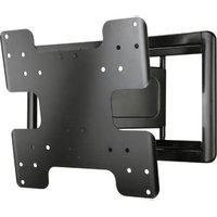
natural_image
Technical line drawing of a metal frame structure with mounting brackets and mounting holes (no text or symbols)We'll Make It Stress-Free
If you have any questions along the way, just give us a call.
• US: +1 (800) 359-5520
• EMEA: +31 (0) 495 580 852
• UK: +44 (0) 800 056 2853
• AUS: +61 (0) 7 3299 7000
We're ready to help!
Scan for easy install video
SANUS.com/3002

IMPORTANT SAFETY INSTRUCTIONS - SAVE THESE INSTRUCTIONS - PLEASE READ ENTIRE MANUAL PRIOR TO USE
Before getting started, let's make sure this mount is perfect for you!
| 1 | Does your TV(including accessories)weigh more than80 lbs. (36.2 kg)? | No – Perfect!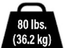 Yes – This mount is NOT compatible.Visit decora.sanus.com or call US: +1 (800) 359-5520 • EMEA: +31 (0) 495 580 852• UK: +44 (0) 800 056 2853 • AUS: +61 (0) 7 3299 7000 to find a compatible mount. Yes – This mount is NOT compatible.Visit decora.sanus.com or call US: +1 (800) 359-5520 • EMEA: +31 (0) 495 580 852• UK: +44 (0) 800 056 2853 • AUS: +61 (0) 7 3299 7000 to find a compatible mount. | ||
| 2 | What is yourwall made of?CAUTION:DO NOT install intodrywall alone | studs?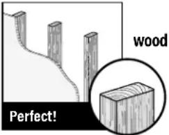 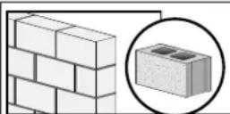 Solid concrete orconcrete block? Solid concrete orconcrete block? Concrete Installation Kit Required (not included)Call Customer Service Concrete Installation Kit Required (not included)Call Customer Service | ||
| 3 | Do you haveall the toolsneeded? | 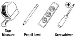 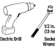 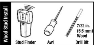 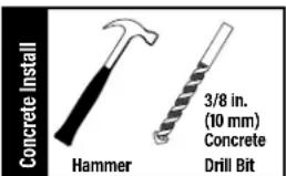 | ||
| 4 | Ready to begin? | Please read through these instructions completely to be sure you're comfortable with this easy install process.Also check your TV owner's manual to see if there are any special requirements for mounting your TV.If you do not understand these instructions or have doubts about the safety of the installation, assembly or use of this product, contact Customer Service atUS: +1 (800) 359-5520 • EMEA: +31 (0) 495 580 852 • UK: +44 (0) 800 056 2853 • AUS: +61 (0) 7 3299 7000.CAUTION: Avoid potential personal injuries and property damage!This product is designed for use in wood stud, solid concrete, and concrete block walls - DO NOT install into drywall aloneThe wall must be capable of supporting five times the weight of the TV and mount combinedDo not use this product for any purpose not explicitly specified by manufacturerManufacturer is not responsible for damage or injury caused by incorrect assembly or use | ||
Dimensions
TV INTERFACE
![1.37in [50mm] MIN 15.75in [400mm] MAX 1.37in [50mm] MIN 16.75in [400mm] MAX](/content/2026/04/676528/images/bd9ef826f14bd2c06f2e5927721fe30ded8d4ac46c4c52cc0542e376a503662b.jpg)
3-D
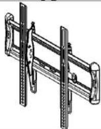
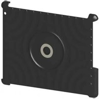
natural_image
Technical line drawing of a mechanical bracket or support structure (no text or symbols)WALL PLATE
![0.75in [19.1mm] 15.42in [381.7mm] 6.50in [185.2mm] 3.91in [93.4mm] 4.00in [101.6mm] 17.78in [451.6mm] 2.93in [74.4mm]](/content/2026/04/676528/images/0e2e2f8081efea10b1c55c494d0def3ce49bf39ed10e188b0508c4cf5ad77483.jpg)
FRONT VIEW - LATERAL SHIFT
![7.87in [200mm] LATERAL SHIFT AT 200MM VESA](/content/2026/04/676528/images/a540b23bbb29f6ec04f512c583cbfa7207c38a872da0b39df80a3f1e6c533e66.jpg)
SIDE VIEW
FULLY ASSEMBLED MOUNT
![18.26in [463.8mm] 16.93in [430mm]](/content/2026/04/676528/images/693f1fd4dc760cc78186e6c7eb564559b97729be0534b7b1fe79dda79a239e06.jpg)
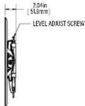
FRONT VIEW - ROLL & CENTER OFFSET
![-15° LEVEL ADJUST 0.38in [9.7/mm] OFFSET](/content/2026/04/676528/images/9cfdeea2c8378ee30fcba871f3b9217ed22940bd4de260a0d02c665364b14254.jpg)
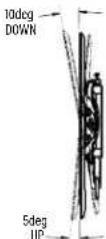
SIDE VIEW - TILT
Parts and Hardware
⚠ WARNING: This product contains small items that could be a choking hazard if swallowed. Before starting assembly, verify all parts are included and undamaged. If any parts are missing or damaged, do not return the damaged item to your dealer; contact Customer Service. Never use damaged parts!

NOTE: Not all hardware included will be used.
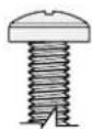
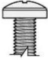
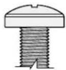
![STEP 1 Parts and Hardware 01 TV Screws [Only one size fits your TV] (m4 x 12mm M4 x 35mm) M4 M5 x 12mm M5 x 35mm M6 M6 x 12mm M6 x 20mm M6 x 15mm M6 x 35mm M8 M8 x 16mm M8 x 20mm M8 x 35mm Washers (qty. 4 each) 02 M4 / M5 M6/M8 Spacer (qty. 4) [If necessary] 03 22mm TV Bracket Left 04 qty. 1 TV Bracket Right 05 qty. 1](/content/2026/04/676528/images/758a5e166dd00371218e43191c186be9eebf6d01ca8df3dee94cc46f78061ffe.jpg)
STEP 2 Parts and Hardware

Concrete Installation Kit CMK1 is NOT INCLUDED
Contact Customer Service to inquire about the additional hardware.
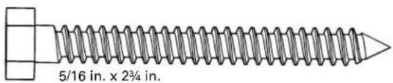
Lag Bolt
C1 qty. 3
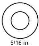
Washer
C2 qty. 3
For concrete installations ONLY

CAUTION: Do not use in drywall or wood
Concrete
Anchor

qty. 3
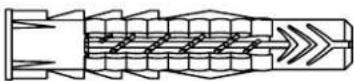
Fischer UX10 x 60R Anchor
STEP 1 Attach Brackets to TV
1.1 Select TV Screw Diameter
M4
M5
O
O
O
M8
[Non-Text]

natural_image
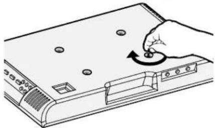
Illustration of a hand pressing a button on a device with a circular arrow indicating rotation (no text or symbols)1.2 Select TV Screw Length
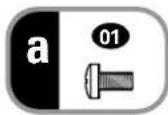
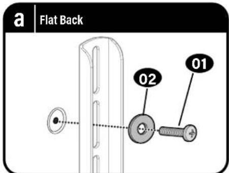
a: For flat-back TVs, no spacers 03 required.
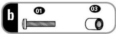
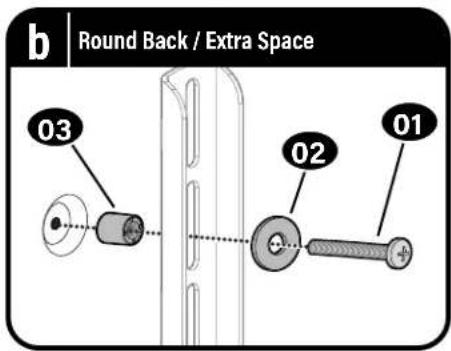
b: Spacers 03 supplied for:
- Round (irregular) back TVs - Extra space needed (for cables or inset mounting holes)
CAUTION:
Verify adequate thread engagement with your screw/washer/spacer combination AND TV bracket.
- Too short will not hold the TV. - Too long will damage the TV.
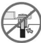
Too Short
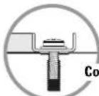
Too Long
1.3 Attach TV Brackets
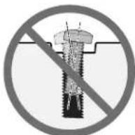
CAUTION: Avoid potential personal injuries and property damage! DO NOT use power tools for this step. Tighten the screws only enough to secure the TV bracket to the TV. DO NOT overtighten the screws.
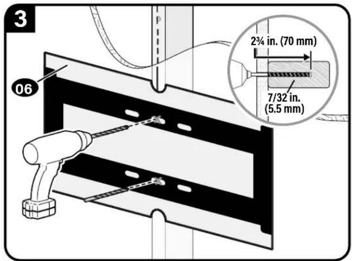
STEP 2A Attach Wall Plate to Wall
Wood Stud Option
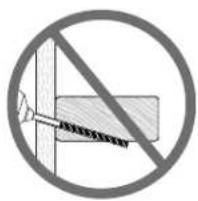
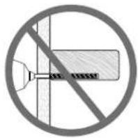
AUTION: Avoid potential personal injury or property damage!
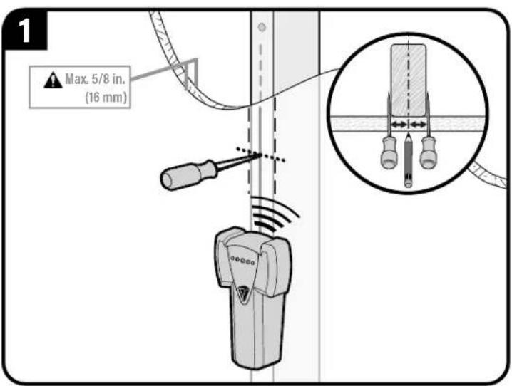
- Drywall covering the wall must not exceed 5/8 in. (16 mm)
● Minimum wood stud size: nominal 2 x 4 in. (51 x 102 mm) actual 1½ x 3½ in. (38 x 89 mm)
• Stud center must be verified.
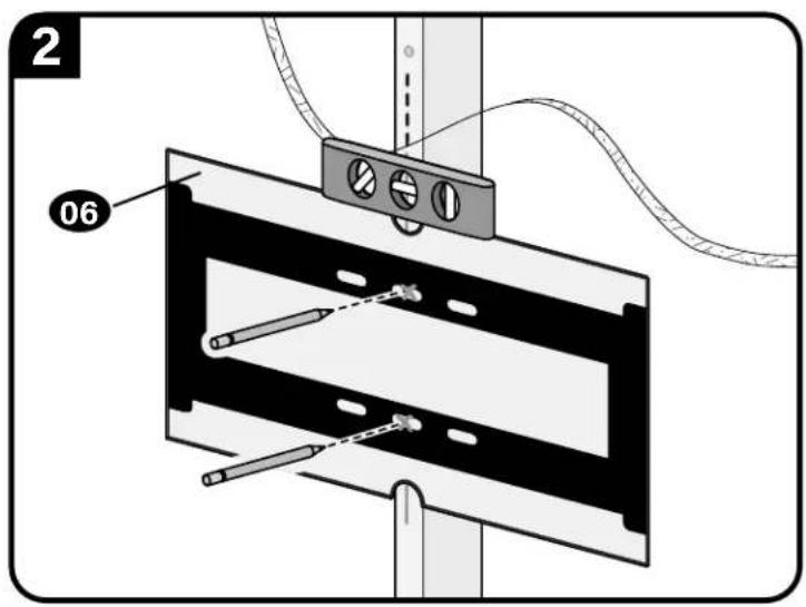
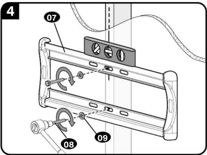
▲ CAUTION: Avoid potential personal injury or property damage!
Improper use could reduce the holding power of the lag bolt 08
Tighten the lag bolts 08 only until the washers 09 are pulled FIRMLY against the wall plate 07.
DO NOT over-tighten the lag bolts 08
Go to STEP 3 on PAGE 12.
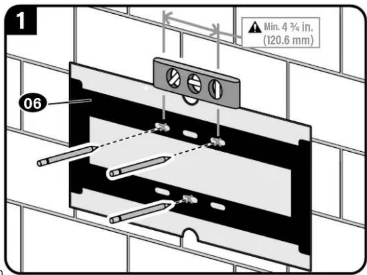
STEP 2B Attach Wall Plate to Wall
Solid Concrete or Concrete Block Option
AUTION: Avoid potential personal injury or property damage!
- Mount the wall plate 07 directly onto the concrete surface
• Minimum solid concrete thickness: 8 in. (203 mm)
● Minimum concrete block size: 8 x 8 x 16 in. (203 x 203 x 406 mm)
Concrete Installation Kit CMK1 is not included
(see page 5) Contact Customer Service to inquire about the additional hardware.
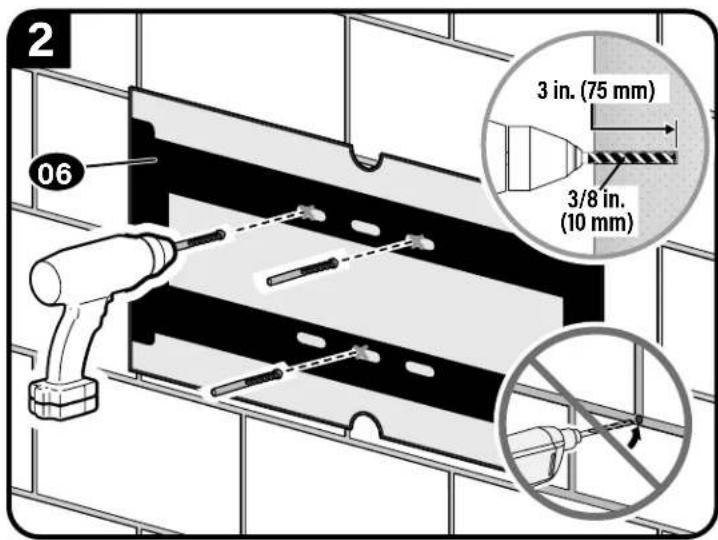
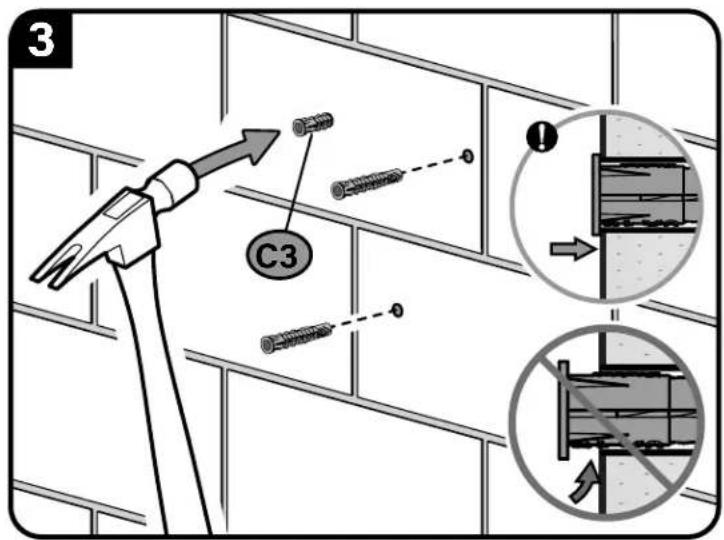
Fischer UX10 x 60R C3 - included in the Concrete Installation Kit CMK1).
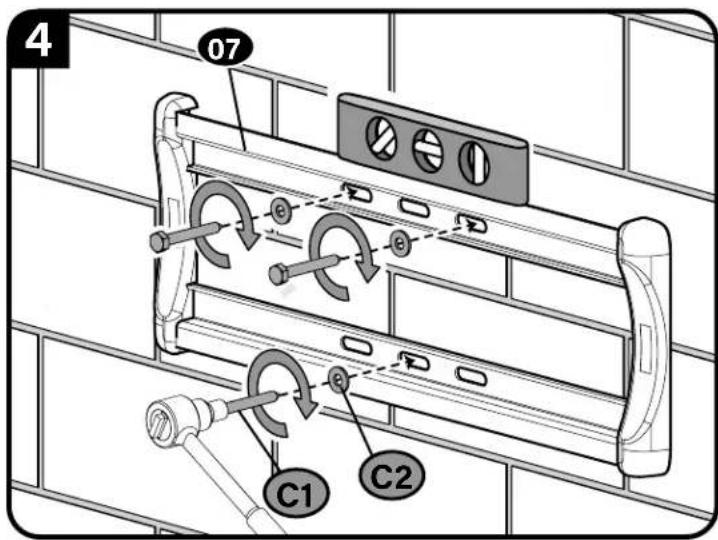
(use ONLY the lag bolts C1 and washers C2 from the Concrete Installation Kit CMK1).
CAUTION: Avoid potential personal injury or property damage!
Improper use could reduce the holding power of the lag bolt C1.
Tighten the lag bolts C1 only until the washers C2 are pulled FIRMLY against the wall plate 07.
DO NOT over-tighten the lag bolts C1.
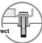
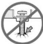
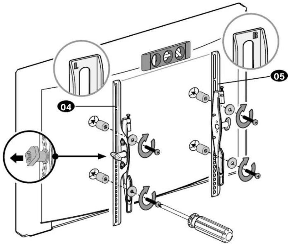
STEP 3 Attach TV to Wall Plate
HEAVY! You may need assistance with this step.
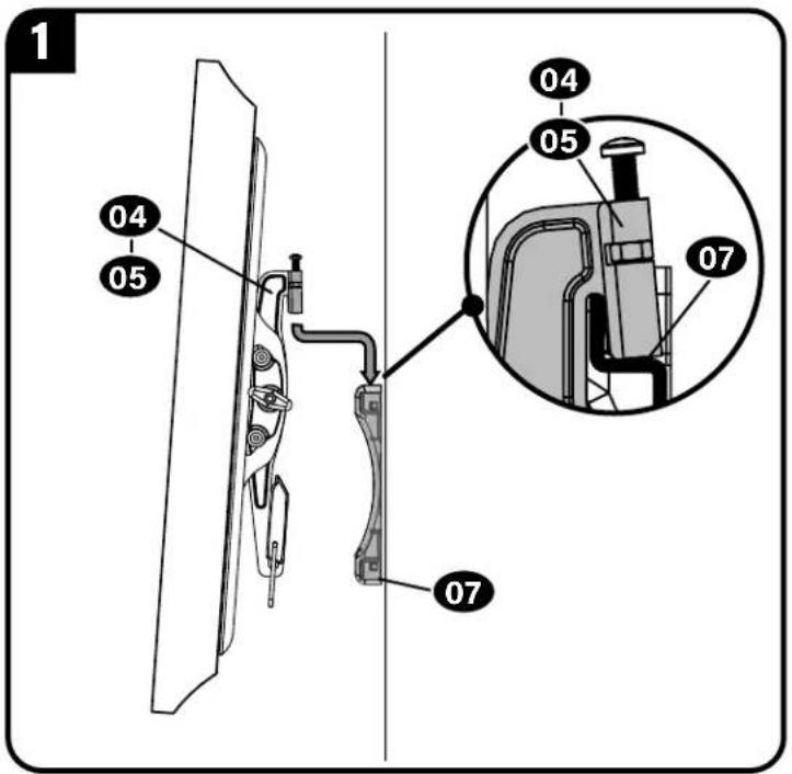
CAUTION: Avoid potential personal injury or property damage! The safety latch must be locked, so the TV is securely fastened to the wall plate 07.
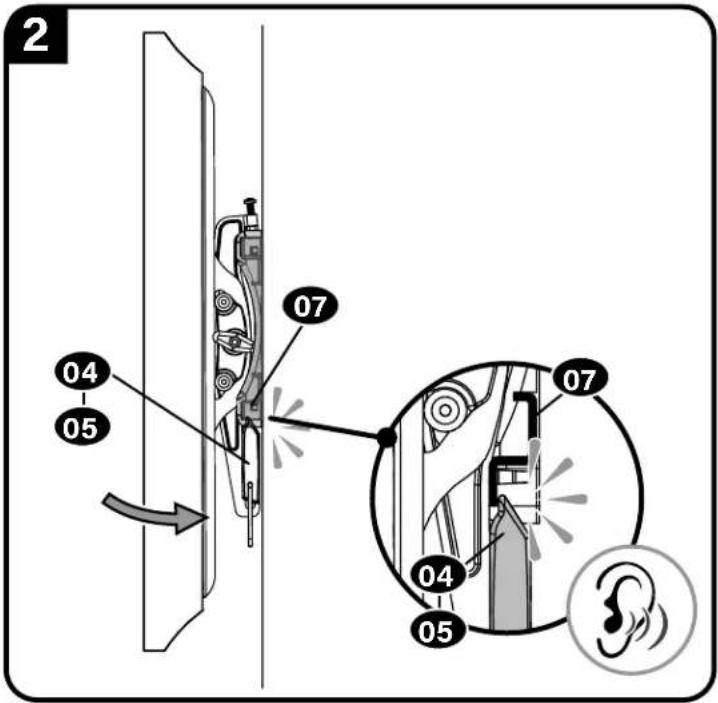
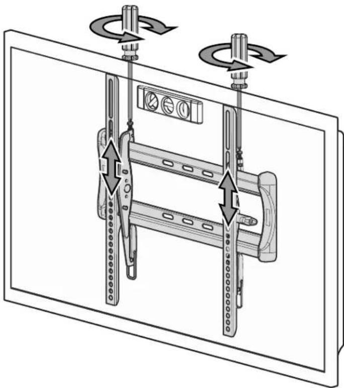
Adjustments
TILT
Your TV should adjust easily when moved, then stay in place.
If your TV is too loose or too tight,
adjust the tilt tension knob Ⓣ.
NOTE: Once your TV is in place, tighten the tilt tension knob to prevent unwanted movement.
LEVEL
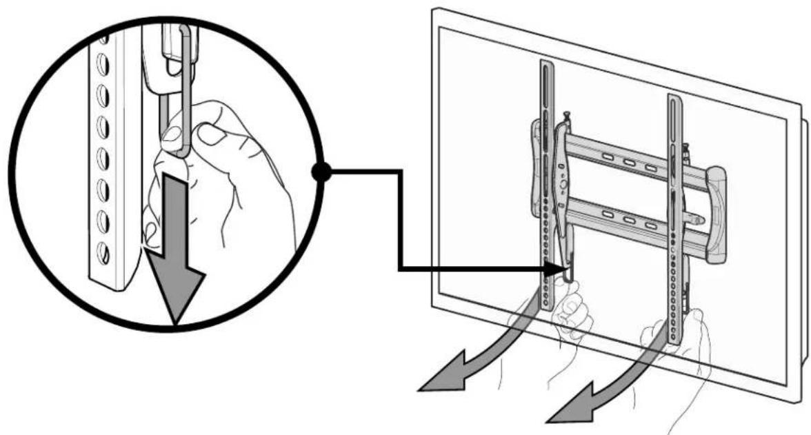
natural_image
Diagram of a mechanical assembly with rotating components and directional arrows indicating motion (no text or symbols)REMOVING THE TV
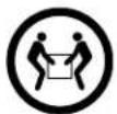
HEAVY! You may need assistance with this step.
ESPAÑOL
Legrand AV Inc.
6436 City West Parkway, Eden Prairie, MN 55344 USA
US: +1 (800) 359-5520 · SANUS.com
Legrand AV Netherlands B.V.
Franklinstraat 14, 6003 DK Weert, Netherlands
EMEA: +31 (0) 495 580 852 · UK: +44 (0) 800 056 2853
Legrand Australia
7/8 Metroplex AVE, Murarrie Queensland, Australia 4172
AUS: +61 (0) 7 3299 7000
Legrand AV Inc. and its affiliated corporations and subsidiaries (collectively, "Legrand"), intend to make this manual accurate and complete. However, Legrand makes no claim that the information contained herein covers all details, conditions, or variations. Nor does it provide for every possible contingency in connection with the installation or use of this product. The information contained in this document is subject to change without notice or obligation of any kind. Legrand makes no representation of warranty, expressed or implied, regarding the information contained herein. Legrand assumes no responsibility for accuracy, completeness or sufficiency of the information contained in this document.
Amazon, Fire TV and all related logos are trademarks of Amazon.com, Inc. or its affiliates.
©2021 Legrand AV Inc. All Rights Reserved. SANUS is a brand of Legrand. SANUS and the SANUS logo are registered trademarks of Legrand.
Legrand AV Inc. • 6436 City West Parkway • Eden Prairie, MN 55344 USA
6901-602951 00