LL11B3 - Flat screen mount SANUS - Free user manual and instructions
Find the device manual for free LL11B3 SANUS in PDF.

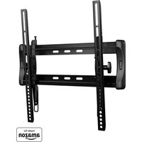
| Product Type | Flat panel wall mount |
| Brand | Sanus |
| Model | LL11B3 |
| Maximum load capacity | 68 kg (150 lb) |
| Material | Steel |
| VESA compatibility | Up to 600 x 400 mm (estimated) |
| Compatible wall types | Wood studs, solid concrete, concrete block |
| Wall plate dimensions | Approximately 660 x 200 mm (estimated) |
| Mount weight | Approximately 5 kg |
| ProSet (leveling adjustment) | Yes, after installation |
| ClickStand (cable release) | Yes |
| Cable management | Yes, integrated |
| Distance from wall | Adjustable via spacers (14, 24, 38 mm) |
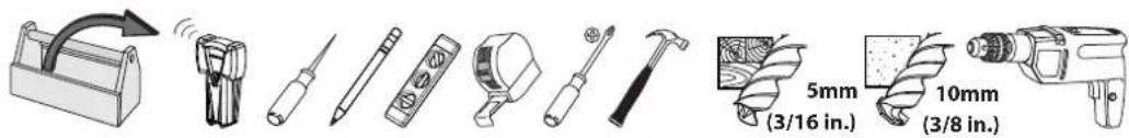
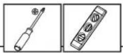
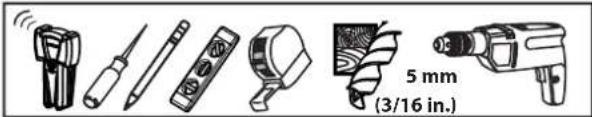
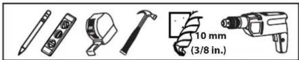
| Required tools | Drill, 5 mm bit (wood) or 10 mm bit (concrete), level, Allen key |
| Maintenance and cleaning | Wipe with soft dry cloth |
| Safety | Do not exceed maximum load; wall must support 5 times total weight |
| Spare parts | Available on order (contact customer service) |
| Repairability | Damaged parts must be replaced with original parts |
| Warranty | Consult the manufacturer |
| General information | Multilingual manual included; free PDF download |
Frequently Asked Questions - LL11B3 SANUS
User questions about LL11B3 SANUS
0 question about this device. Answer the ones you know or ask your own.
Ask a new question about this device
Download the instructions for your Flat screen mount in PDF format for free! Find your manual LL11B3 - SANUS and take your electronic device back in hand. On this page are published all the documents necessary for the use of your device. LL11B3 by SANUS.
USER MANUAL LL11B3 SANUS
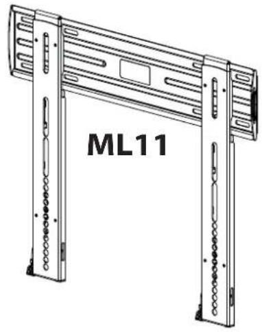
ML11 and LL11 Instruction Manual
natural_image
Technical line drawing of a mechanical device labeled ML11, showing two vertical supports with internal components (no text or symbols beyond label)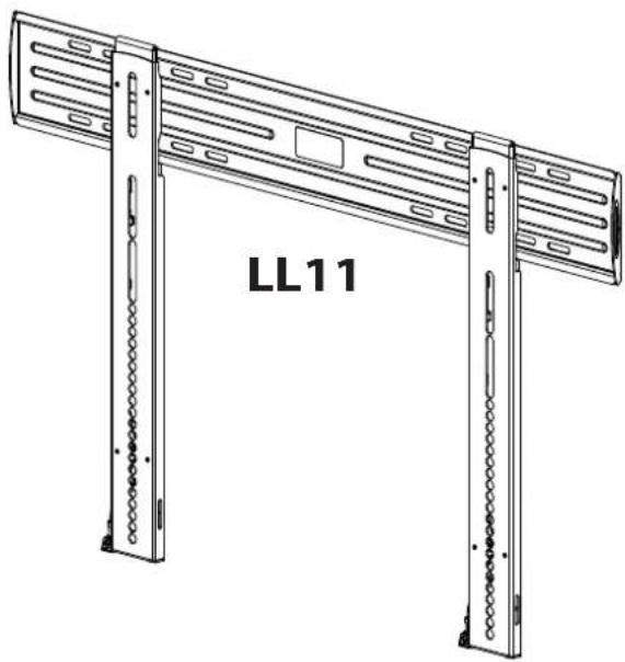
natural_image
Technical line drawing of a server rack unit labeled LL11, showing two vertical supports with slots and mounting holes (no text or symbols beyond label)We are here to help!
Please contact Customer Service with any questions.
Customer Service
Americas: 800-359-5520 • 952-225-6013 • info@sanus.com
UK: 0800-056-2853
Europe, Middle East, and Africa: +31 (0) 495 580 852 • europe.sanus@milestone.com
Asia Pacifi c: 86 755 8996 9226 • sanus.ap@milestone.com
SANUS • 6436 City West Parkway • Eden Prairie, MN • 55344 • USA
©2014 Milestone AV Technologies. All rights reserved. Sanus is a division of Milestone.
All other brand names or marks are used for identification purposes and are trademarks of their respective owners.

sanus.com
English - How to use this manual
For best results, reference both the text and illustrations. Cut along the dashed lines to match your language with the illustrations.
OR Select one item or the other.
OPT This item is optional
English Text Pages 3-11
Weight capacity-includes TV and any accessories-DO NOT EXCEED:
ML11 45.4 kg (100 lb.)
LL11 68 kg (150 lb.)
CAUTION: Avoid potential personal injuries and property damage!
Do not use this product for any purpose not explicitly specified by manufacturer.
The wall must be capable of supporting five times the weight of the monitor and mount combined.
This product includes directions and hardware for use with wood stud, solid concrete and concrete block walls. For information on how to use this product with steel stud walls contact Customer Service and ask about the SSMK1 steel stud mounting kit.
If you do not understand these instructions, or have doubts about the safety of the installation, assembly or use of this product, contact manufacturer Customer Service or call a qualified contractor.
Manufacturer is not responsible for damage or injury caused by incorrect assembly or use.
Required Tools
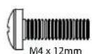
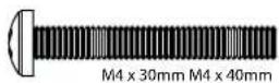
Supplied Parts and Hardware
⚠ WARNING: This product contains small items that could be a choking hazard if swallowed.
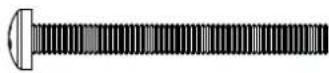
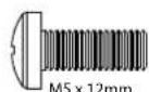
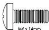
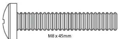
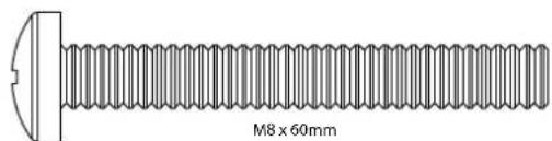
Before starting assembly, verify all parts are included and undamaged. If any parts are missing or damaged, do not return the damaged item to your dealer; contact Customer Service. Never use damaged parts! NOTE: M4, M5, M6, or M8 describes the diameter, mm describes the length of screws that are labeled M# X ##mm. Not all hardware included will be used.
![LL11 ML11 [01] x 1 [02] x 2](/content/2026/04/734831/images/831e1759331e7c65f99412e1d5dcf92e74dee3f1b2e1f2936f481c9ef1f994fd.jpg)
![[01] x 1 [02] x 2](/content/2026/04/734831/images/1a945d03665dab2717376ed1b581ac7732ff9b6eec77d9e6e3d88730afdc6083.jpg)
![M7 x 70 mm [03] x 4 [04] x 4 UX 10 [05] x 1 [06] x 1](/content/2026/04/734831/images/86eaa86cc267aca2bb1aa991da8502b0b4a816ef2ab409857d9665f53615a17d.jpg)
[07] x 4
[08] × 4 [09] × 4
[10] × 4 [11] × 4
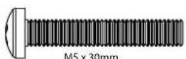
M5 x 30mm
[12] x 4
[13] x 4

[14]×4 [15]×4
natural_image
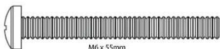
Technical illustration of a threaded bolt with a flat head and central hole, labeled M6 x 55mm (no other text or symbols)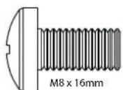
[16] x 4
[17] x 4
[18]×4
natural_image
Simple line drawing of a rectangular object with a tapered end and a small protrusion at the top (no text or symbols)[24] × 4[23] × 4[22] × 4[2
1 Select TV Hardware and Mount TV Brackets
1-1 Select the hardware diameter and length
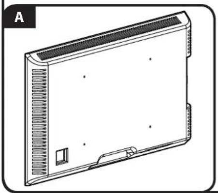
Your TV type will help you determine which hardware configuration to use. Match your type of TV to the suggested hardware configuration on the next page.
A. Installation option without spacers (TVs with fl at backs)
B. Installation option using 14mm spacers (TVs with irregular backs)
C. Installation option using 24mm or 38mm spacers (For TVs with irregular backs that require more length than the 14mm spacer provides.)
Hand thread screws into the threaded inserts on the back of your TV to determine the correct screw diameter (M4, M5, M6, or M8).
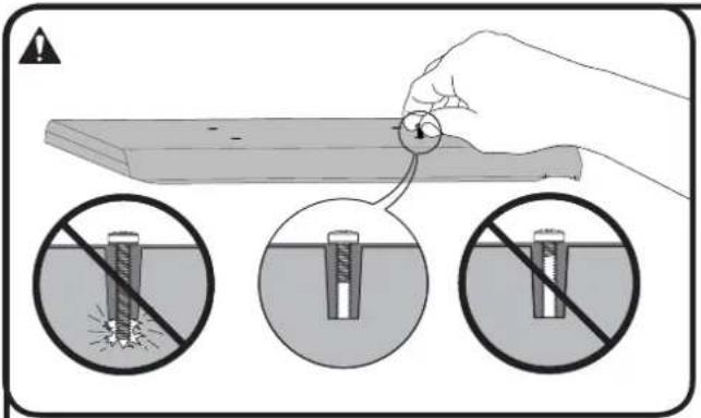
CAUTION: Avoid potential personal injuries and property damage! Verify that there are adequate threads to secure the brackets to the monitor. If you encounter resistance, stop immediately and contact customer service. Use the shortest screw and spacer combination to accommodate your needs. Using hardware that is too long may damage your TV.
natural_image
Line drawing of a rectangular electronic device with ventilation grilles and mounting holes (no text or symbols)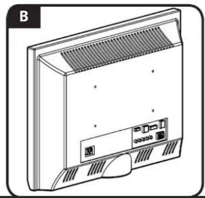
natural_image
Line drawing of a front panel with ventilation grille and ports (no text or symbols)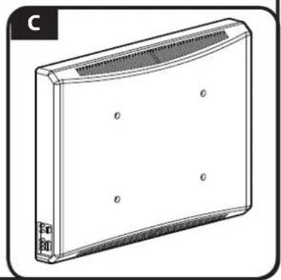
natural_image
Line drawing of a rectangular electronic device with a curved top and side connectors (no text or symbols)1-2 Attach Brackets to a TV with a fl at back
![[02]](/content/2026/04/734831/images/43991d9cb3d38b1b2c3f060358e61aa8bf49dd3024de5ae219e239151d428df2.jpg)
Confir rm that the brackets are level on the back of the TV. If you require additional space for cables, recesses, or protrusions, choose one of the confi gurations below.
![[02] [19, 20] [07, 10, 13, 16]](/content/2026/04/734831/images/477b57a2d7baf49ed25dc08727bffa5ca6868f387ba12dbed456f847ecd02f29.jpg)
![[02] [22, 23, 24] [21] [02] [22, 23, 24] [21]](/content/2026/04/734831/images/55370801df2d6ba995fce435551503bd982ca6e1a54620aee63363efe07f9ac4.jpg)
- Push the shoulder washer [21] through the appropriate openings of the brackets [02].
- Snap shoulder washer [21] into the spacer you selected in step 1-1.
If your TV has a curved or obstructed back, or if you need more room to accommodate cables, recesses, or protrusions, use either the 14mm, 24mm, or 38mm spacer [22, 23, or 24].
![[02]](/content/2026/04/734831/images/57e2086943f67bb32f95f71669581e7bdb8eb4f8d400e185be9e804b5c811b69.jpg)
Confir rm that the brackets are level on the back of the TV. Standard confi gurations are shown. For special applications, or if you are uncertain about your hardware selection, contact Customer Service.
![[02] [21] [22, 23] [19, 20] [08, 09, 11, 12, 14, 17]](/content/2026/04/734831/images/26c323e4ef0311b67f877bd71cbf31140d882236b883d6d3aaec4cad5f99e69d.jpg)

![M6/M8 ONLY! [02] [21] [20] [15, 18]](/content/2026/04/734831/images/afd1e640ce6ddc877cdab72cba767be6395c9cf619a1944f53bc7776dddb4579.jpg)
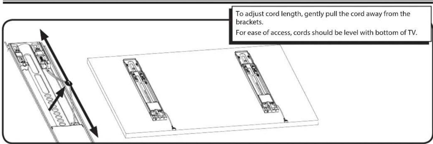
2 Adjust Cord Length
3 Mount the Wall Plate
Wood Stud Mounting
3-1 Locate studs
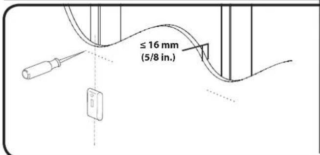
For assistance in determining wall plate location, see Height Finder at sanus.com.
Locate studs. Verify the center of the stud(s) using an awl or edge to edge stud fi nder.
▲ CAUTION: Avoid potential personal injuries and property damage!
Drywall covering the wall must not exceed 16 mm (5/8 in.).
Minimum wood stud size: common 51 x 102 mm (2 x 4 in.) nominal 38 x 89 mm (11/2 x 31/2 in.).
3-2 Mark the wall
![[01] LL11 406-609 mm (16-24 in.) ML11 406 mm (16 in.) Level th](/content/2026/04/734831/images/0b97552340a0713796970639f50f706ac775de9c4858dfcc22c16d502a7d6224.jpg)
Level the wall plate [01] and mark the hole locations.
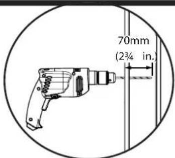
3-3 Drill pilot holes
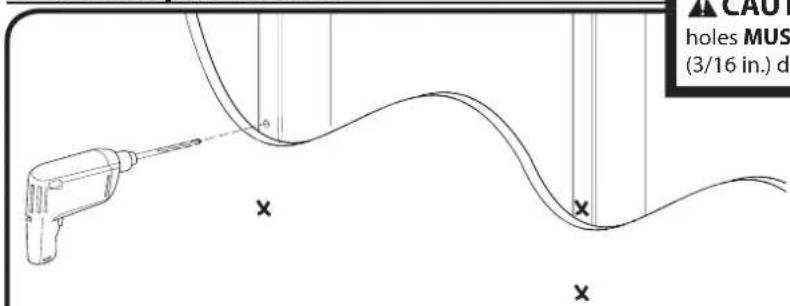
CAUTION: Avoid potential injuries or property damage! Pilot holes MUST be drilled to a depth of 70 mm (2¾ in.), using a 5mm (3/16 in.) diameter drill bit.
3-4 Tighten lag bolts
![[01] [05] [03] DO NOT over-ti Tighten the lag wall plate [01].](/content/2026/04/734831/images/898771af564f66034ca42fffad634b958d26f47b4ceac30f65006c68d38ab20f.jpg)
Using a drill and the allen driver bit [05] tighten lag bolts [03] only until they are pulled firmly against the wall plate.
CAUTION: Avoid potential injuries or property damage!
DO NOT over-tighten the lag bolts [03].
- Tighten the lag bolts only until they are pulled firmly against the wall plate [01].
3 Mount the Wall Plate Solid Concrete or Concrete Block
3-1 Mark the wall
![[01] 406 mm (16 in.)](/content/2026/04/734831/images/136b2abdb13ab0f50ff231c9f40e08c3e4b3fca2bdd2710035d5de631db20586.jpg)
For assistance in determining wall plate location, see Height Finder at sanus.com.
Level the wall plate [01] and mark the hole locations.
▲ CAUTION: Avoid potential injuries or property damage!
Mount the wall plate [01] directly onto the concrete surface.
Minimum solid concrete thickness: 203mm (8 in.).
Minimum concrete block size: 203 x 203 x 406 mm (8 x 8 x 16 in.).
Minimum space between fasteners: 406 mm (16 in.).
3-2 Drill pilot holes
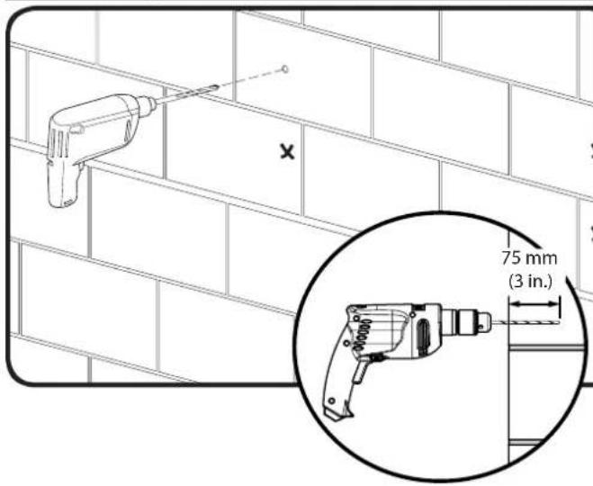
CAUTION: Avoid potential injuries or property damage!
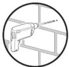
- Pilot holes MUST be drilled to a depth of 75 mm (3 in.) using a 10 mm (3/8 in.) diameter drill bit.
■ Never drill into the mortar between blocks.
natural_image
Simple line drawing of a drill bit inside a frame (no text or symbols)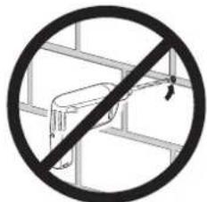
3-3 Insert anchors and lag bolts
![[04] [01] [04] [05]](/content/2026/04/734831/images/df7d11583a7bd83483b14e8a0707efed03d4e3ade87f55b89c1df88d5e4ea360.jpg)
Insert lag bolt anchors [04]. Then insert lag bolts [03] using a drill and the allen driver bit [05].
▲ CAUTION: Improper use could reduce the holding power of the lag bolt. To avoid potential injuries or property damage:
Be sure the anchors [04] seat flush with the concrete surface.
- Tighten the lag bolts [03] only until the they are pulled firmly against the wall plate [01].
DO NOT over-tighten the lag bolts [03].
![Hang your TV onto the wall plate [01]. HEAVY! You will need assistance with this step. [01] [02]](/content/2026/04/734831/images/aa5d4e8f86564d9b39c13713f30d5c174752d28fe383c2114331d0e3db57d4f2.jpg)
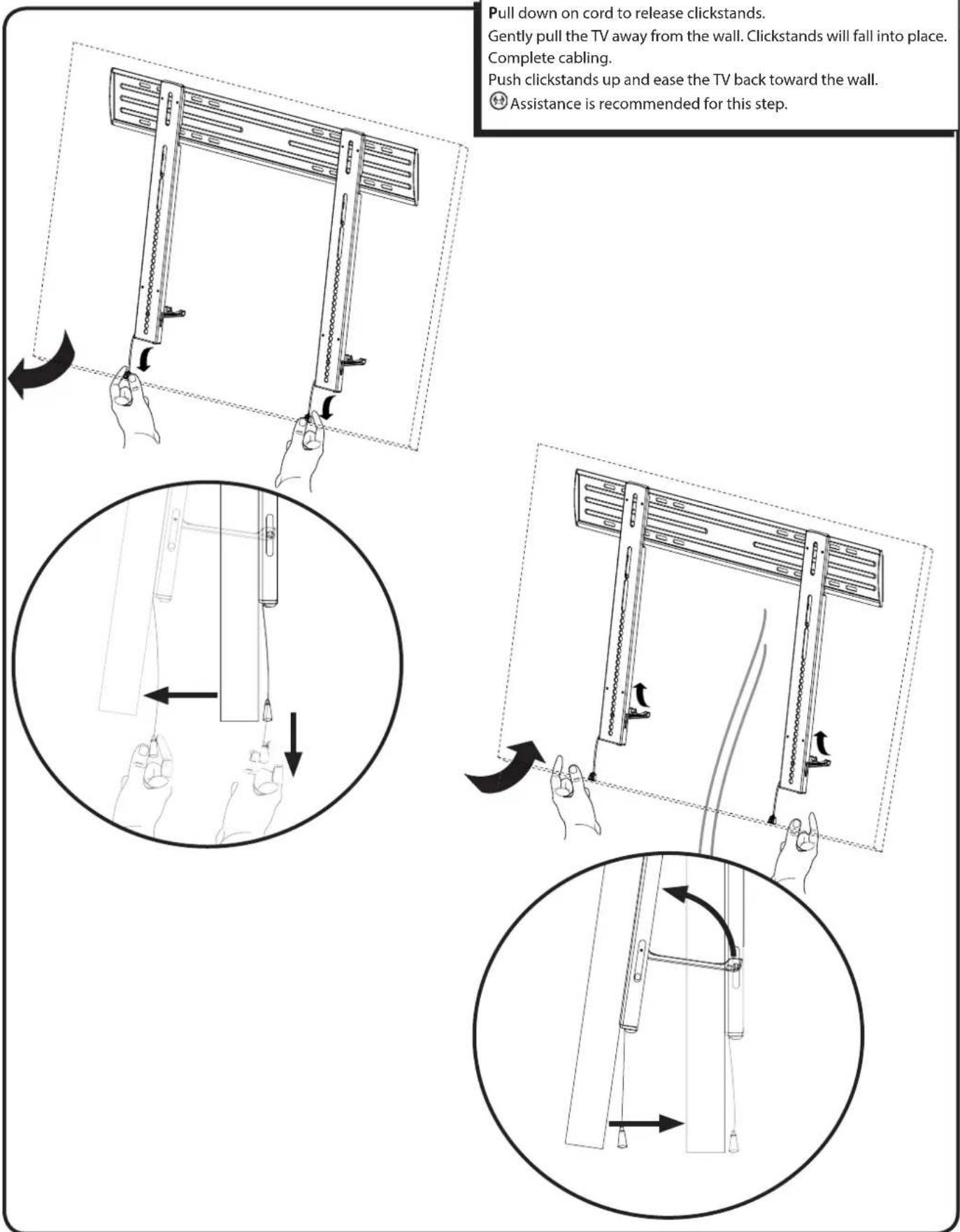
Pull down on cord to release clickstands.
Gently pull the TV away from the wall. Clickstands will fall into place. Complete cabling.
Push clickstands up and ease the TV back toward the wall.
Assistance is recommended for this step.
![Adjust level of TV using post installation ProSet. ±2.5° ± 12.7 mm (.5 in.) ± 12.7 mm (.5 in.) ±2.5° ± 12.7 mm (.5 in.) ± 12.7 mm (.5 in.) [06]](/content/2026/04/734831/images/1811d49f77c12d359764849234e76e11adeb255eb626a24d4255069f138485a8.jpg)
Français
CONSIGNES DE SÉCURITÉ IMPORTANTES – CONSERVEZ CES INSTRUCTIONS – VEUILLEZ LIRE ATTENTIVEMENT LE MANUEL AVANT D'UTILISER CE PRODUIT
Milestone AV Technologies and its affiliated corporations and subsidiaries (collectively, "Milestone"), intend to make this manual accurate and complete. However, Milestone makes no claim that the information contained herein covers all details, conditions, or variations. Nor does it provide for every possible contingency in connection with the installation or use of this product. The information contained in this document is subject to change without notice or obligation of any kind. Milestone makes no representation of warranty, expressed or implied, regarding the information contained herein. Milestone assumes no responsibility for accuracy, completeness or sufficiency of the information contained in this document.