SE 14-2 125 - Sander Flex - Free user manual and instructions
Find the device manual for free SE 14-2 125 Flex in PDF.


User questions about SE 14-2 125 Flex
0 question about this device. Answer the ones you know or ask your own.
Ask a new question about this device
Download the instructions for your Sander in PDF format for free! Find your manual SE 14-2 125 - Flex and take your electronic device back in hand. On this page are published all the documents necessary for the use of your device. SE 14-2 125 by Flex.
USER MANUAL SE 14-2 125 Flex
natural_image
Illustration of a cleaning power tool with a brush and base (no text or symbols)text_image
Technical diagram of a power tool with numbered parts and exploded view, including a close-up inset showing internal components.natural_image
Illustration of two different types of power tools (cylindrical and square) being adjusted, showing tool positioning and cutting process (no text or symbols present)text_image
"clic" "clic"natural_image
Illustration of a hand cutting a circular object with a knife, showing mechanical components and motion direction (no text or symbols)text_image
Diagram illustrating a tool interacting with a mechanical component, labeled with steps 1 and 2.text_image
Diagram illustrating a mechanical assembly process with labeled parts and an inset showing a close-up of the component.natural_image
Mechanical gear assembly with a cross symbol overlay (no text or labels)natural_image
Illustration of a cleaning or cleaning tool with a brush applying material, showing no text or symbols.natural_image
Illustration of a cleaning or cleaning tool with a brush and handle (no text or symbols)natural_image
Close-up of a car's side panel with a right-handled arrow pointing to a circular symbol (no text or labels)natural_image
Close-up of a car's side panel with a heat sink and directional arrow indicator (no text or symbols)text_image
Diagram showing a device with a numbered component labeled '3' and directional arrows, possibly indicating a process or system.natural_image
Two hands using a power tool on a tiled floor, no text or symbols visibletext_image
Diagram of a cleaning or cleaning tool with numbered annotations indicating steps 1 and 2.natural_image
Person using a power tool on a workbench, no visible text or symbolstext_image
B. H. Q. - 1Manager Research & Development (R & D)
Klaus Peter WeinperEckhard Rühle Head of Quality Department (QD)
15.05.2015
Noise and vibration 18
Technical specifications ..... 19
Overview 20
Instructions for use 21
Maintenance and care 25
C ∈ Declaration of Conformity ..... 25
UK Declaration of Conformity ..... 25
Disposal information 26
Exemption from liability 26
Symbols used in this manual

WARNING!
Denotes impending danger.
Non-observance of this warning may result indeath or extremely severe injuries.

CAUTION!
Denotes a possibly dangerous situation.
Non-observance of this warning may result insight injury or damage to property.

NOTE
Denotes application tips and important information.
Symbols on the power tool

Before switching on the power tool, read the operating manual!
Wear goggles!

Wear ear protection!

Disposal information for the old machine (see page 26)!
For your safety

WARNING!
Before using the power tool, please read and follow:
–these operating instructions,
-the "General safety instructions" on the handling of power tools in the enclosed booklet (leaflet-no.: 315.915),
–the currently valid site rules and the regulations for the prevention of accidents.
This power tool is state of the art and has been constructed in accordance with the acknowledged safety regulations.
Nevertheless, when in use, the power tool may be a danger to life and limb of the user or a third party, or the power tool or other property may be damaged.
The power tool may be operated only if it is - a s i n t e n d e d ,
-in perfect working order.
Faults which impair safety must be repaired immediately.
Intended use
The surface sander SE 14-2 125/SE 14-2 150 is designed
– for commercial use in industry and trade,
– for the dry surface grinding of metal, stone, and wood as well as for the dry sanding of paintwork,
– for use with Velcro sandpaper on backing pads which FLEX offers for this device,
– for use with flap sanding discs which FLEX offers for this device,
Tools must be authorised to run at a speed of at least 3,000 rpm.
Cutting-off and grinding wheels must not be used on this electric power tool.
When using the surface sander SE 14-2 125/SE 14-2 150, connect a Class M dust extractor.
Safety instructions

WARNING!
Read all safety instructions and other instructions. Failure to observe the safety instructions and other instructions may result in an electric shock, fire and/or serious injuries. Keep all safety instructions and other instructions in a safe place for the future.
■ This electric power tool must be used as a grinder, sander and polisher. Read all safety warnings, instructions, illustrations and specifications provided with this power tool.
Failure to follow all instructions listed below may result in electric shock, fire and/or serious injury.
■ Operations such as wire brushing or cutting-off are not recommended to be performed with this power tool.
Operations for which the power tool was not designed may create a hazard and cause personal injury.
■ Do not use accessories which are not specifically designed and recommended by the tool manufacturer.
Just because the accessory can be attached to your power tool, it does not assure safe operation.
■ The rated speed of the accessory must be at least equal to the maximum speed marked on the power tool.
Accessories running faster than their rated speed can break and fly apart.
■ The outside diameter and the thickness of your accessory must be within the capacity rating of your power tool.
Incorrectly measured insertion tools cannot be adequately shielded or controlled.
■ Sanding discs, sanding pads or other accessories must fit exactly on the grinding spindle of your electric power tool. Insertion tools, which do not fit exactly on the grinding spindle of the electric power tool, rotate unevenly, vibrate violently and may result in loss of control.
■ Do not use a damaged accessory. Before use, always check insertion tools for splinters and cracks, sanding pad for cracks, wear and severe abrasion.
If power tool or accessory is dropped, inspect for damage or install an un-damaged accessory.
After inspecting and installing an accessory, position yourself and bystanders away from the plane of the rotating accessory and run the power tool at maximum no-load speed for one minute. Damaged accessories will normally break apart during this test time.
■ Wear personal protective equipment. Depending on application, use face shield, safety goggles or safety glasses. If appropriate, wear a dust mask, hearing protection, protective gloves and/or a special apron which protect you from small sanding and material particles.
The eye protection must be capable of stopping flying debris generated by various operations. The dust mask or respirator must be capable of filtrating particles generated by your operation. Prolonged exposure to high intensity noise may cause hearing loss.
- Keep bystanders a safe distance away from work area. Anyone entering the work area must wear personal protective equipment.
Fragments of workpiece or of a broken accessory may fly away and cause injury beyond immediate area of operation.
■ Hold power tool by insulated gripping surfaces only, when performing an operation where the cutting accessory may contact hidden wiring or its own cord.
Cutting accessory contacting a "live" wire may make exposed metal parts of the power tool "live" and shock the operator.
■ Position the cord clear of the spinning accessory.
If you lose control, the cord may be cut or snagged and your hand or arm may be pulled into the spinning accessory.
■ Never lay the power tool down until the accessory has come to a complete stop. The spinning accessory may grab the surface and pull the power tool out of your control.
■ Do not run the power tool while carrying it at your side.
Accidental contact with the spinning accessory could snag your clothing, pulling the accessory into your body.
■ Regularly clean the power tool's air vents.
The motor's fan will draw the dust inside the housing and excessive accumulation of powdered metal may cause electrical hazards.
■ Do not operate the power tool near flammable materials.
Sparks could ignite these materials.
■ Do not use accessories that require liquid coolants.
Using water or other liquid coolants may result reresult in electrocution or shock.
Special safety instructions for sanding:
■ Use only those sanding tools authorised for use with your electric power tool and the guard designated for this sanding tool.
Sanding tools, which are not designated for use with the electric power tool, cannot be adequately shielded and are unsafe.
■ The guard must be attached securely to the electric power tool and adjusted to ensure maximum safety, i.e. the smallest possible part of the sanding tool is exposed to the operator.
The guard should protect the operator from fragments and accidental contact with the sanding tool.
■ Sanding tools may be used for the recommended applications only. For example: Never sand with the side area of a diamond sanding pad.
Diamond sanding pads are designed to remove material with the underside of the sanding pad. If a lateral force is applied to these sanding tools, they may shatter.
■ Always use undamaged clamping flanges in the correct size and shape for the insertion tool you have selected.
Suitable flanges support the insertion tools and therefore reduce the risk of a break.
■ Do not use worn insertion tools from larger electric power tools.
Insertion tools for larger electric power tools are not designed for the higher speeds of smaller electric power tools and may break.
Special safety instructions for sanding:
- Do not use oversized sanding sheets, but follow the manufacturer's specifications for the size of sanding sheets.
Sanding sheets which project over the sanding pad may cause injuries as well as block and rip the sanding sheets or cause a kickback.
Special safety instructions for polishing:
■ Do not allow any loose portion of the polishing bonnet or its attachment strings to spin freely.
Tuck away or trim any loose attachment strings.
Loose and spinning attachment strings can entangle your fingers or snag on the workpiece.
Kickback and Related Warnings:
Kickback is the sudden reaction to a pinched or snagged rotating insertion tool, such as a sanding disc, sanding pad, wire brush, etc. Pinching or snagging may cause a rotating insertion tool to stop abruptly.
For example, if an abrasive wheel is snagged or pinched by the workpiece, the edge of the wheel that is entering into the pinch point can dig into the surface of the material causing the wheel to climb out or kick out.
The wheel may either jump toward or away from the operator, depending on direction of the wheel's movement at the point of pinching. Abrasive wheels may also break under these conditions.
For example, if a sanding disc is snagged or pinched by the workpiece, the edge of the sanding disc which is entering the workpiece may become caught and cause the sanding disc to break off or kick back.
The sanding disc then moves towards or away from the operator, depending on the direction in which the disc is rotating at the point of pinching. Sanding discs may also break under these conditions.
A recoil occurs if the electric power tool is used incorrectly or improperly.
A recoil can be prevented by appropriate precautions as described below.
■ Maintain a firm grip on the power tool and position your body and arm to allow you to resist kickback forces.
Always use auxiliary handle, if provided, for maximum control over kickback or torque reaction during start-up.
The operator can control torque reactions or kickback forces, if proper precautions are taken.
■ Never place your hand near the rotating accessory.
Accessory may kickback over your hand.
■ Do not position your body in the area where power tool will move if kickback occurs.
Kickback propels the electric power tool in the direction opposite to the movement of the sanding disc at the point of pinching.
■ Use special care when working corners, sharp edges etc. Avoid bouncing and snagging the accessory.
Corners, sharp edges or bouncing have a tendency to snag the rotating accessory and cause loss of control or kickback.
This causes a loss of control or kickback.
■ Do not attach a saw chain woodcarving blade or toothed saw blade.
Such blades create frequent kickback and loss of control.
Additional safety instructions

WARNING!
Touching or inhaling harmful/toxic dust is a hazard to the operator and to people in the vicinity.
It is not recommended to sand lead paint. Lead paint should be removed by a specialist only.
■ Do not work on materials which release hazardous substances (e.g. asbestos). Take precautions if hazardous, combustible or explosive dust is likely to occur. Wear protective dust mask. Use dust extraction system.

DAMAGE TO PROPERTY!
■ The mains voltage and the voltage specifications on the rating plate must correspond.
Noise and vibration
The noise and vibration values have been determined in accordance with EN 60745.
The A evaluated noise level of the power tool is typically:
– Sound pressure level: 79.7 dB(A);
– Sound power level: 90.7 dB(A);
- Uncertainty: K = 3 dB.
Total vibration value
(when grinding with sanding sheet):
– Emission value: a h_DS < 2.5 m/s^2
- Uncertainty: K = 1.5 m/s

WARNING!
The indicated measurements refer to new power tools. Daily use causes the noise and vibration values to change.

NOTE
The vibration emission level given in this information sheet has been measured in accordance with a standardised test given in EN 60745 and may be used to compare one tool with another. It may be used for a preliminary assessment of exposure. The declared vibration emission level represents the main applications of the tool.
However if the tool is used for different applications, with different accessories or poorly maintained, the vibration emission may differ. This may significantly increase the exposure level over the total working period.
For a precise estimation of the vibration load the times should also be considered during which the power tool is switched off or even running, but not actually in use. This may significantly decrease the exposure level over the total working period.
Identify additional safety measures to protect the operator from the effects of vibration such as: maintain the tool and the accessories, keep the hands warm, organisation of work patterns.

CAUTION!
Wear ear protection at a sound pressure above 85 dB(A).
Technical specifications
| Machine type Surface sander SE 14-2 125 SE 14-2 | 150 | ||
| Mains voltage V/Hz 230/50 | |||
| Protection class | ☐/II | ||
| Power input W 1,400 | |||
| Power output W 880 | |||
| Speed r.p.m. 600 – 2,100 | |||
| Tool holder | M14 | ||
| Max. disc diameter | mm | 125 | 150 |
| Weight according to “EPTA Procedure 01/2003” (without power cord) | kg | 2.6 | 2.7 |
Overview
text_image
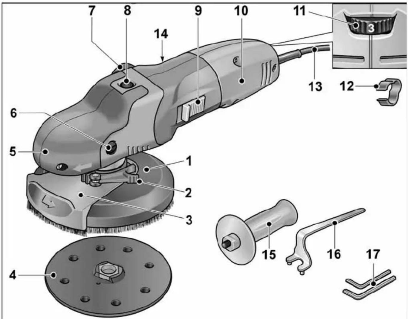
Technical diagram of a power tool with numbered parts and exploded view, including a close-up inset showing internal components.1 Guard hood with brush ring
a) SE 14-2 125: ∅ 125 mm
b) SE 14-2-150: ∅ 150 mm
2 Clamping lever for guard hood
3 Pivoted edge segment
4 Velcro sanding disc
5 Handle cover
With air outlet and direction-of-rotation arrow.
6 Fastening screw for handle cover
7 Connection for extractor
8 S p i n d l e l
Secures the spindle when the tool is changed.
9 S w i t c h r o
Switches the power tool on and off. With notched position for continuous operation.
10 Handle
11 Dial for preselecting the speed
12 Cable holder (3x)
For guiding the cable securely along the suction hose
13 4.0 m power cord with mains plug
14 Rating plate *
15 Auxiliary Handle
16 Clamping nut wrench
17 Allen key (A/F 4 + A/F 5)
* not illustrated
Instructions for use

WARNING!
Before performing any work on the power tool, pull out the mains plug.

CAUTION!
The available mains voltage and the voltage specifications on the rating plate must be the same.
Before switching on the power tool
■ Unpack power tool and accessories and check that no parts are missing or damaged.
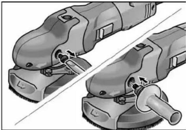
Attaching the auxiliary handle
The auxiliary handle can be attached to improve handling of the electric power tool.
natural_image
Illustration of two different types of power tools (no text or symbols present)■ Remove fastening screw from the left side of the grip hood.
■ Screw in and tighten auxiliary handle.
When removing the auxiliary handle, put back the screw which was removed beforehand.
Connecting an extraction system

NOTE
It is recommended to use the FLEX special extractor S 47 M.
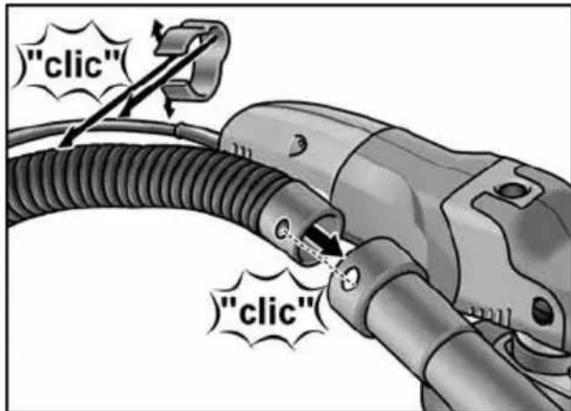
■ Attach extraction hose to the connector on the guard hood.
■ Attach power cord to the extraction hose using the enclosed cable holders (3x).
text_image
"clic" "clic"■ Connect extraction hose to the dust extraction system. Follow the operating instructions for the dust extraction system! Check the attachment! If required, use an appropriate adapter.
Attaching/changing the Velcro sandpaper
■ Pull out the mains plug.
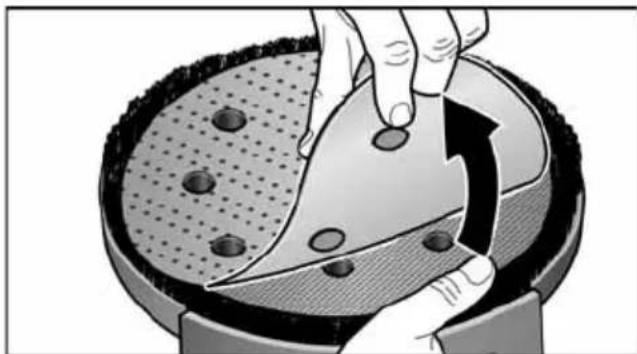
■ Remove worn sanding tool from the backing pad.
natural_image
Illustration of a hand using a tool to cut a circular object on a textured surface, with no visible text or symbols.■ Place the Velcro sandpaper in the centre of the backing pad and press on.
Note position of the holes to ensure that the sanding dust is extracted.
■ Conduct a test run to check that the sanding tool is clamped in the centre.
Working with flap sanding discs
i NOTE
Flap sanding discs are a component of the "Metal working" accessory set.
■ Pull out the mains plug.
■ Press and hold down the spindle lock.
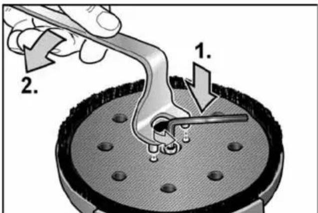
■ Loosen the Velcro pad by hand or using a two-hole wrench.
i NOTE
If the Velcro pad is stuck, hold the gear shaft in place using an Allen key.
text_image
Diagram illustrating a mechanical process with labeled steps 1 and 2, showing tool application on a component.■ Screw Velcro pad anti-clockwise off the spindle.
■ Place clamping flange (A) on spindle.
■ Place flap sanding disc (B) on clamping flange.
■ Screw the clamping nut (C), with flange face up, onto the spindle.
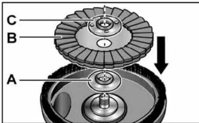
text_image
C B A■ Press and hold down the spindle lock.
■ Tighten clamping nut clockwise using the holding wrench.
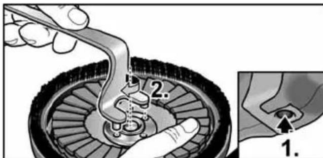
text_image
Medical illustration showing a procedure on car wheel assembly with labeled steps 1 and 2■ Conduct a test run to check that the sanding tool is clamped in the centre.
CAUTION!
Never use a diamond sanding disc not approved by FLEX on this electric power tool. Risk of damaging the device!

natural_image
Mechanical gear assembly with a cross symbol overlay (no text or labels)Check position of the guard:
The brush ring should protrude over the sanding tool by approx. 0–1 mm. Correct if required.
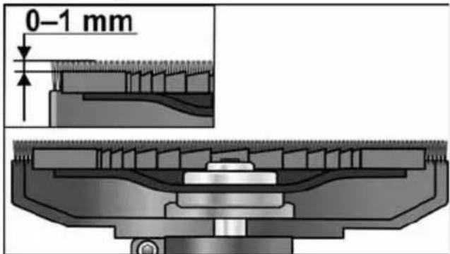
text_image
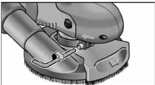
0-1 mm■ Loosen clamping lever on guard hood.
■ Set the guard hood to the required height.
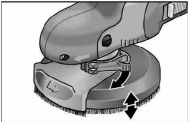
natural_image
Close-up of a cleaning brush tool with a curved arrow indicating rotation (no text or symbols)■ Tighten the clamping lever.
NOTE If the clamping force decreases, the clamping can be adjusted by tightening the hexagon socket screw on the clamping lever.
natural_image
Illustration of a cleaning or cleaning tool with a brush and handle (no text or symbols)Switching the electric power tool on and off
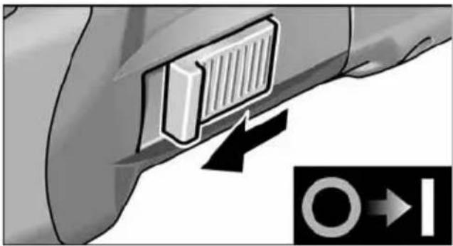
Brief operation without engaged switch rocker:
natural_image
Close-up of a car's side panel with a right-handled arrow pointing to a circular symbol (no text or labels visible)■ Push the switch rocker forwards and hold in position.
■ To switch off the power tool, release the switch rocker.
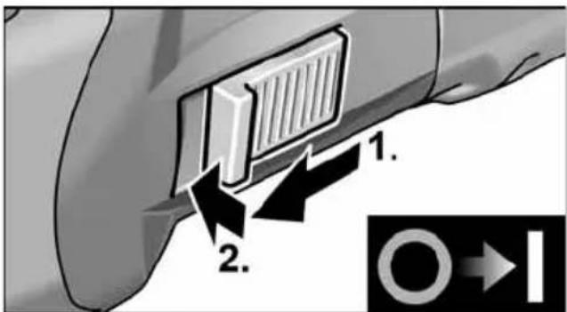
Continuous operation with engaged switch rocker:
i NOTE
Following a power failure, the switched-on electric power tool will not start running again.
text_image
1. 2.■ Push the switch rocker forwards and engage by pressing the front end.
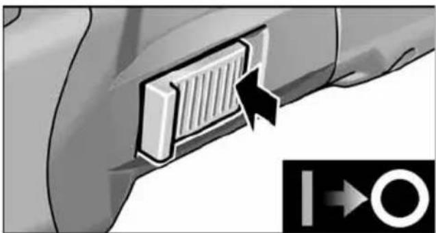
Switch off the machine:
natural_image
Close-up of a car's side panel with a right-handled button and directional arrow (no text or symbols)■ To switch off the power tool, release the switch rocker by pressing the rear end.
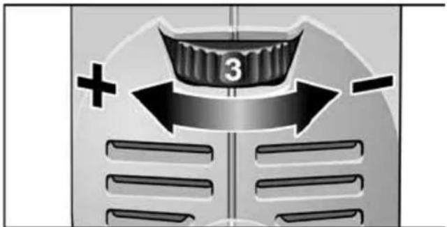
Preselecting the speed
text_image
+ 3 -To set the operating speed, move the dial to the required value.
The speed can be set from 600–2,100 min ^-1 .
Setting Speed (min -1 )
| 1 | 6 |
| 2 | 9 |
| 3 | 1 |
| 4 | 1 |
| 5 | 1 |
| 6 | 2 |
Working with the power tool

WARNING!
The rotating sanding disc must not come intocontact with sharp projecting objects.
Danger of kickback! Damage to sanding pad. If the sanding pad is damaged or severely worn, it must be replaced.

CAUTION!
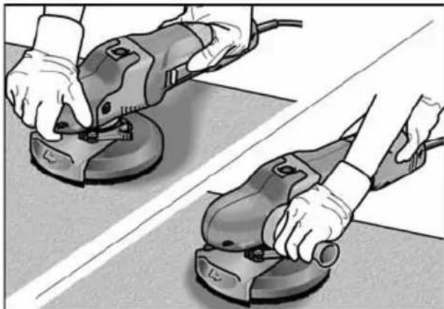
Hold the electric power tool with both hands!
natural_image
Two hands using a power tool on a tiled floor, no text or symbols visible- Attach sanding tool.
- Check position of the guard.
- Connect dust extraction system.
-
Insert mains plug.
-
Switch on dust extraction system.
- Switch on the power tool.
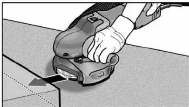
- Place electric power tool on the work surface. The brush ring must be flush with the work surface.
- Increase the pressure to bring the sanding pad into contact with the work surface. In doing so, slew the electric power tool with overlapping movements.
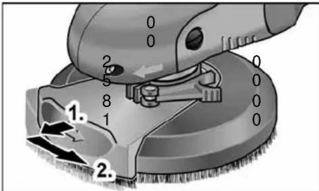
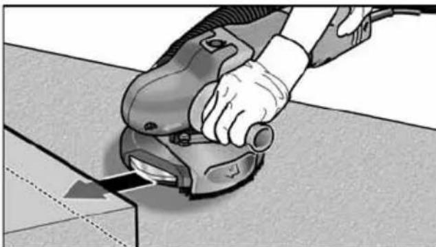
- Sanding in corners:
- Switch off the power tool and wait until the sanding tool has come to a standstill.
– Pull out pivoted edge segment and swivel to left.
0 0
text_image
0 0 2 5 8 1 1. 0 0 0 0 2.- Switch on power tool again.
- Place electric power tool on the work surface.
natural_image
Person using a power tool on a workbench, no visible text or symbols- After work, switch off the electric power tool and pull out the mains plug.
Brush ring
The guard features a brush ring.
This ring has two functions:
- As the ring projects above the surface of the sanding pad, it is the ring which comes into contact with the work surface first. As a result, the sanding pad is brought parallel to the work surface before the san-ding tool comes into contact with the work surface. This avoids a sickle-shaped depression caused by the edge of the san-ding pad.
- The ring retains the dust until it is extracted by the dust extractor.
If the brush ring is damaged or excessively worn, it should be replaced.
A replacement brush set is available from any FLEX customer service centre.
Maintenance and care

WARNING!
Before performing any work on the electric power tool, pull out the mains plug.
Cleaning

WARNING!
Do not use water or liquid detergents.

CAUTION!
When cleaning with compressed air, always wear goggles.
■ Regularly blow out the housing interior and motor with dry compressed air.
■ Clean the guard and pivoted edge segment using dry compressed air.
Repairs
Repairs may be carried out by an authorised customer service centre only.

NOTE
During the warranty period do not loosen thescrews on the motor housing. Non-compliance will deem the guarantee obligations of the manufacturer null and void.
Spare parts and accessories
Other accessories, in particular insertion tools, can be found in the manufacturer's catalogues.
Exploded drawings and spare-part lists can be found on our homepage:
www.flex-tools.com
CE Declaration of Conformity
We declare under our sole responsibility that the product described under “Technical specifications” conforms to the following standards or normative documents:
EN 60745 in accordance with the regulations of the directives
2004/108/EC (until 19.04.2016),
2014/30/EU (from 20.04.2016),
2006/42/EC, and 2011/65/EC.
Responsible for technical documents:
text_image
B. H. Q. - 1Klaus Peter WeinperEckhard F
Manager Research & Development (R & D)
Head of Quality
Department (QD)
15.05.2015
Declaration of Conformity
We as the manufacturer: FLEX Elektro-werkzeuge GmbH,
Business address: Bahnhofstr. 15, 71711 Steinheim, Germany
declare under our sole responsibility, that the product(s) described under "Technical specifications" fulfills all the relevant provisions of The Supply of Machinery
(Safety) Regulations S.I. 2008/1597 and also fulfills all the relevant provisions of the following UK Regulations:
Electromagnetic Compatibility Regulations
S.I. 2016/1091, The Restriction of the Use of
Certain Hazardous Substances in Electrical and Electronic Equipment Regulations
S.I. 2012/3032 and are manufactured in accordance with the following designated Standards:
BS EN 60745-1:2010,
BS EN 60745-2-3:2011,
BS EN 55014-1:2017,
BS EN 55014-2:2015,
BS EN 61000-3-2:2014,
BS EN 61000-3-3:2013
Place of declaration: Steinheim, Germany.
Responsible person: Peter Lameli,
Contact details for Great Britain: FLEX Power Tools Limited, Unit 8 Anglo Office Park, Lincoln Road, HP 12, 3RH Buckinghamshire, United Kingdom.

text_image
i.v. P.Claud Peter Lameli Technical Head Klaus Peter Weinper Head of Quality Department (QD)19.05.2021
Disposal information

WARNING!
Render redundant power tools unusable byremoving the power cord.

EU countries only
Do not throw electric power tools into the household waste!
In accordance with the European Directive 2012/19/EC on Waste Electrical and Electronic Equipment and transposition into national law used electric power tools must be collected separately and recycled in an environmentally friendly manner.

NOTE
Please ask your dealer about disposal options!
Exemption from liability
The manufacturer and his representative are not liable for any damage and lost profit due to interruption in business caused by the product or by an unusable product.
The manufacturer and his representative are not liable for any damage which was caused by improper use of the power tool or by use of the power tool with products from other manufacturers.
Table des matières
natural_image
Three circular icons representing human, safety, and electronic devices (no text or symbols)text_image
Technical diagram of a power tool with numbered parts and exploded view, including a close-up inset showing internal components.natural_image
Illustration of two different types of power tools (cylindrical and square) being adjusted, showing tool positioning and cutting process (no text or symbols present)text_image
"clic" "clic"natural_image
Illustration of a hand cutting a circular object with a knife, showing mechanical components and motion direction (no text or symbols)text_image
Diagram illustrating a mechanical or electrical process with labeled parts and directional arrows indicating movement or force.text_image
Medical illustration showing a hand using a tool to adjust a mechanical component, with labeled parts and an inset showing a close-up of the component.natural_image
Mechanical gear assembly with a cross symbol overlay (no text or labels)natural_image
Close-up of a cleaning brush tool with a curved arrow indicating rotation (no text or symbols)natural_image
Illustration of a cleaning or cleaning tool with a brush and handle (no text or symbols visible)natural_image
Close-up of a car's side panel with a right-handled arrow pointing to the front panel (no text or symbols visible)text_image
Diagram showing a car's side panel with labeled components and directional arrow, likely illustrating vehicle or component positioning.natural_image
Close-up of a car's side panel with a right-handled arrow pointing to a grid-like component, no text or symbols visible.natural_image
Two hands using a power tool on a tiled floor, no text or symbols visibletext_image
Diagram of a cleaning or cleaning device with numbered components and directional arrows indicating process flow.natural_image
Close-up of hands using a power tool to cut or apply material on a workbench (no text or symbols visible)text_image
Bolts Q - rManager Research & Development (R & D)
Klaus Peter WeinperEckhard F Head of Quality Department (QD)
15.05.2015
text_image
Technical diagram of a power tool with numbered parts and exploded view, including a close-up inset showing internal components.natural_image
Illustration of two different types of power tools or motors, showing mechanical components and tool paths (no text or symbols present)text_image
"clic" "clic"natural_image
Illustration of a hand using a tool to cut a circular object on a textured surface, with an arrow indicating rotation (no text or symbols present)text_image
Diagram illustrating a mechanical process with labeled parts, showing tool application and assembly steps.text_image
Diagram illustrating a mechanical assembly process with labeled parts and an inset showing a close-up of the component.natural_image
Mechanical gear assembly with a cross symbol overlay (no text or labels)natural_image
Illustration of a cleaning or cleaning tool with a brush and directional arrows indicating process (no text or symbols)natural_image
Illustration of a cleaning or cleaning tool with a brush and handle (no text or symbols)natural_image
Close-up of a car's side panel with a right-handled arrow pointing to a circular symbol (no text or labels)natural_image
Close-up of a car's side panel with a mounted air vent and directional arrow indicator (no text or symbols)natural_image
Two hands using a power tool on a tiled floor, no text or symbols visibletext_image
Diagram of a cleaning or cleaning tool with labeled parts 1 and 2, showing mechanical components and directional arrows.natural_image
Close-up of a hand using a power tool to cut a component on a workbench (no text or symbols visible)text_image
B. B. - rManager Research & Development (R & D)
Klaus Peter WeinperEckhard F Head of Quality Department (QD)
15.05.2015
text_image
Technical diagram of a power tool with numbered parts and exploded view, including a close-up inset showing internal components.natural_image
Illustration of two different types of power tools (cyeing and polishing) being adjusted, showing tool positioning and cutting process (no text or symbols present)text_image
"clic" "clic"natural_image
Illustration of a hand using a knife to cut a circular object on a textured surface, with no visible text or symbols.text_image
Diagram illustrating a mechanical process with labeled steps 1 and 2, showing tool application on a component.text_image
Medical illustration showing a hand using a tool to adjust a mechanical component, with labeled parts and an inset showing a close-up of the component.natural_image
Mechanical gear assembly with a cross symbol overlay (no text or labels)natural_image
Close-up of a cleaning brush tool with a curved arrow indicating rotation (no text or symbols)■ Ajustar la palanca de ajuste.

NOTA
natural_image
Illustration of a cleaning or cleaning tool with a brush and handle (no text or symbols)natural_image
Close-up of a car's side panel with a right-handled arrow pointing to a circular symbol (no text or labels)natural_image
Close-up of a car's side panel with a mounted grille and directional arrow indicator (no text or symbols)natural_image
Two hands using a power tool on a tiled floor, no text or symbols visibletext_image
Diagram of a cleaning or cleaning tool with labeled parts 1 and 2, showing mechanical components and directional arrows.natural_image
Close-up of a hand using a power tool to cut or apply material on a workbench (no text or symbols visible)text_image
Technical diagram of a power tool with numbered parts and exploded view, including a close-up inset showing internal components.natural_image
Illustration of two different types of power tools (cylindrical and square) being adjusted, showing tool positioning and cutting process (no text or symbols present)text_image
"clic" "clic"natural_image
Illustration of a hand using a tool to cut a circular object on a textured surface, with no visible text or symbols.text_image
Diagram illustrating a mechanical or electrical process with labeled parts 1 and 2, showing tool application and component positioning.text_image
Medical illustration showing a surgical procedure on a car wheel, with labeled steps 1 and 2.natural_image
Mechanical gear assembly with a cross symbol overlay (no text or labels)natural_image
Illustration of a cleaning brush tool with directional arrows indicating process flow (no text or symbols)natural_image
Illustration of a cleaning or cleaning tool with a brush and handle (no text or symbols visible)natural_image
Close-up of a car's side panel with a right-handled arrow pointing to a circular symbol (no text or labels)natural_image
Close-up of a car's side panel with a heat sink and directional arrow indicator (no text or symbols)natural_image
Two hands using a power tool on a tiled floor, no text or symbols visibletext_image
Diagram of a cleaning or cleaning tool with numbered annotations indicating steps 1 and 2.natural_image
Close-up of a hand using a power tool to cut or apply material on a flat surface (no text or symbols visible)text_image
Technical diagram of a power tool with numbered parts and exploded view, including a close-up inset showing internal components.natural_image
Illustration of two different types of power tools (cylindrical and square) being adjusted, showing tool positioning and cutting process (no text or symbols present)text_image
"clic" "clic"natural_image
Illustration of a hand cutting a circular object into a bowl with a knife, showing mechanical components and motion direction (no text or symbols)text_image
Diagram illustrating a mechanical or electrical process with labeled components and directional arrows indicating movement or force.text_image
Medical illustration showing a hand using a tool to adjust a mechanical component, with labeled parts and an inset showing a close-up of the component.natural_image
Mechanical gear assembly with a cross symbol overlay (no text or labels)Stand van de beschermkap controleren:
natural_image
Close-up of a cleaning brush tool with a curved arrow indicating rotation (no text or symbols)■ Draai de spanhendel vast.

LET OP
natural_image
Illustration of a cleaning or cleaning tool with a brush and handle (no text or symbols visible)natural_image
Close-up of a car's side panel with a right-handled arrow pointing to a circular symbol (no text or labels)natural_image
Close-up of a car's side panel with a right-angle indicator (no text or symbols visible)natural_image
Two hands using a power tool on a tiled floor, no text or symbols visibletext_image
Diagram of a cleaning or cleaning device with numbered components and directional arrows indicating process flow.– Schakel de machine weer in.
natural_image
Close-up of hands using a power tool to cut or apply material on a workbench (no text or symbols visible)Klaus Peter WeinperEckhard F Head of Quality Department (QD)
text_image
Technical diagram of a power tool with numbered parts and exploded view, including a close-up inset showing internal components.natural_image
Illustration of two different types of power tools (no text or symbols present)text_image
"clic" "clic"natural_image
Illustration of a hand using a tool to cut a circular object with holes, showing mechanical components and motion (no text or symbols)Læg velcro slibepapiret centreret på bagskiven og tryk det fast.
text_image
Diagram illustrating a tool interacting with a mechanical component, labeled with numbered steps 1 and 2.text_image
Diagram illustrating a mechanical assembly process with labeled parts and an inset showing a close-up of the component.natural_image
Mechanical gear assembly with a cross symbol overlay (no text or labels)natural_image
Illustration of a cleaning or cleaning tool with directional arrows indicating process flow (no text or symbols)natural_image
Illustration of a cleaning or cleaning tool with a brush and handle (no text or symbols visible)natural_image
Close-up of a car's side panel with a right-handled arrow pointing to a circular symbol (no text or labels)■ Skub vippekontakten fremad og hold den fast.
■ Slip vippekontakten for at slukke.
Konstant drift med indgreb:
i
BEMAERK
natural_image
Close-up of a car's side panel with a heat sink and directional arrow indicator (no text or symbols)■ Frigør vippekontakten ved at trykke på bagerste ende for at slukke.
text_image
Diagram showing a medical or surgical device with labeled components and directional arrows, including a plus sign and a number 3.natural_image
Two hands using a power tool on a tiled floor, no text or symbols visibletext_image
Diagram of a cleaning or cleaning tool with numbered parts and directional arrows indicating process flownatural_image
Person using a power tool on a workbench, no visible text or symbolsManager Research & Development (R & D)
Head of Quality Department (QD)
15.05.2015
text_image
Technical diagram of a power tool with numbered parts and exploded view, including a close-up inset showing internal components.natural_image
Illustration of two different types of power tools (cylindrical and cylindrical) being adjusted, showing tool positioning and adjustment mechanism (no text or symbols present)text_image
"clic" "clic"■ Avsugingsslangen tilkoples til avsugingsanlegget. Ta hensyn til betjeningsveiledningen for avsugingsanlegget! Kontroller festet! Om nødvendig må det brukes en passende adapter.
natural_image
Illustration of a hand using a tool to cut a circular object with holes, showing mechanical components and motion (no text or symbols)text_image
Diagram illustrating a mechanical process with labeled steps 1 and 2, showing tool application on a component.text_image
Diagram illustrating a mechanical assembly process with labeled parts and an inset showing a close-up of the component.natural_image
Mechanical gear assembly diagram with no visible text or symbolsnatural_image
Illustration of a cleaning or cleaning tool with a brush applying material, showing no text or symbols.■ Skru spennspaken fast.
i HENVISNING
natural_image
Illustration of a cleaning or cleaning tool with a brush and handle (no text or symbols visible)natural_image
Close-up of a car's side panel with a right-handled arrow pointing to a button, and a circular icon with arrows indicating direction (no text or symbols)natural_image
Close-up of a car's side panel with a heat sink and directional arrow indicator (no text or symbols)text_image
Diagram showing a device with labeled components and directional arrows, including a plus sign and a number 3.natural_image
Two hands using a power tool on a tiled floor, no text or symbols visiblenatural_image
Close-up of a hand using a power tool to clean or adjust a mechanical component (no text or symbols visible)Manager Research & Development (R & D)
Head of Quality Department (QD)
15.05.2015
text_image
Technical diagram of a power tool with numbered parts and exploded view, including a close-up inset showing internal components.natural_image
Illustration of two different types of power tools (no text or symbols present)text_image
"clic" "clic"natural_image
Illustration of a hand using a tool to cut a circular object with holes, showing mechanical components and motion direction (no text or symbols)text_image
Diagram illustrating a mechanical tool interacting with a component, labeled with parts 1 and 2.text_image
Medical illustration showing a hand using a tool to adjust a car wheel component with numbered parts and an inset close-up of the insertion site.natural_image
Mechanical gear assembly with a central shaft and cross symbol (no text or labels)natural_image
Close-up illustration of a cleaning brush applying material to a circular base, showing tool movement (no text or symbols)natural_image
Illustration of a cleaning or cleaning tool with a brush and handle (no text or symbols visible)natural_image
Close-up of a car's side panel with a right-handled arrow pointing to a circular symbol (no text or labels)natural_image
Close-up of a car's side panel with a heat sink and directional arrow indicator (no text or symbols)natural_image
Two hands using a power tool on a tiled floor, no text or symbols visibletext_image
Diagram of a cleaning or cleaning device with labeled parts 1 and 2, showing tool movement and component alignment.natural_image
Close-up of hands using a power tool to cut or apply a mechanical component on a workbench (no text or symbols visible)Manager Research & Development (R & D)
Head of Quality Department (QD)
15.05.2015
text_image
Technical diagram of a power tool with numbered parts and exploded view, including a close-up inset showing internal components.1 Suojus, jossa on harjareuna
a) SE 14-2 125: ∅ 125 mm
b) SE 14-2-150: ∅ 150 mm
natural_image
Illustration of two different types of power tools (no text or symbols present)text_image
"clic" "clic"natural_image
Illustration of a hand using a tool to cut a circular object on a textured surface, with no visible text or symbols.text_image
Diagram illustrating a mechanical or dental procedure with labeled parts and directional arrows indicating movement or force.text_image
Diagram illustrating a mechanical assembly process with labeled parts and an inset showing a close-up of the component's tip.natural_image
Mechanical gear assembly with a central shaft and a cross symbol, no text or labels presentnatural_image
Illustration of a cleaning brush tool with directional arrows indicating process flow (no text or symbols)natural_image
Illustration of a cleaning or cleaning tool with a brush and handle (no text or symbols)natural_image
Close-up of a car's side panel with a right-handled arrow pointing to the front panel (no text or symbols visible)natural_image
Close-up of a car's side panel with a right-handled arrow pointing to a grille (no text or symbols visible)natural_image
Two hands using a power tool on a tiled floor, no text or symbols visiblenatural_image
Close-up of a hand using a power tool to clean or adjust a mechanical component (no text or symbols visible)Klaus Peter WeinperEckhard F Head of Quality Department (QD)
text_image
Technical diagram of a power tool with numbered parts and exploded view, including a close-up inset showing internal components.1 Π ρ o φ u λ α
βούρτσας
a) SE 14-2 125: ∅ 125 mm
b) SE 14-2-150: ∅ 150 mm
natural_image
Illustration of two different types of power tools (glasses and a tool) being adjusted, showing mechanical components without any text or symbols.text_image
"clic" "clic"natural_image
Illustration of a hand using a tool to cut a circular object on a textured surface, with no visible text or symbols.text_image
Diagram illustrating a mechanical process with labeled steps 1 and 2, showing tool application on a component.text_image
Diagram illustrating a mechanical assembly process with labeled parts and an inset showing a close-up of the component.natural_image
Mechanical gear assembly with a central shaft and a cross symbol (no text or labels)natural_image
Illustration of a cleaning or cleaning tool with a brush applying material, showing no text or symbols.natural_image
Close-up illustration of a cleaning or cleaning tool with a brush and handle (no text or symbols visible)natural_image
Close-up of a car's side panel with a right-handled arrow pointing to a white circular symbol (no text or labels)natural_image
Close-up of a car's side panel with a heat sink and directional arrow indicator (no text or symbols)natural_image
Two hands using a power tool on a tiled floor, no text or symbols visibletext_image
Diagram of a cleaning or cleaning device with labeled parts 1 and 2, showing tool movement arrows.natural_image
Close-up of a hand using a power tool to cut or spread material on a flat surface (no text or symbols visible)text_image
B. H. Q. - 1Manager Research &
Development (R & D)
15.05.2015
text_image
Technical diagram of a power tool with numbered parts and exploded view, including a close-up inset showing internal components.natural_image
Illustration of two different types of power tools or motors, showing mechanical components and tool paths (no text or symbols present)text_image
"clic" "clic"natural_image
Illustration of a hand using a tool to cut a circular object with dots, showing an arrow indicating rotation (no text or symbols present)text_image
Diagram illustrating a mechanical tool interacting with a component, labeled with parts 1 and 2.text_image
Diagram illustrating a mechanical assembly process with labeled parts and an inset showing a close-up of the component.natural_image
Mechanical gear assembly diagram with no visible text or symbolsnatural_image
Illustration of a cleaning or cleaning tool with a brush applying material, showing no text or symbols.natural_image
Illustration of a cleaning or cleaning tool with a brush and handle (no text or symbols)natural_image
Close-up of a car's side panel with a right-handled arrow pointing to a circular symbol (no text or labels)natural_image
Close-up of a car's side panel with a heat sink and directional arrow indicator (no text or symbols)natural_image
Illustration of two hands using a power tool on a tiled floor (no text or symbols visible)text_image
Diagram of a cleaning or cleaning tool with numbered annotations indicating steps 1 and 2.natural_image
Close-up of a hand using a power tool to cut or apply a component on a textured surface (no text or symbols visible)text_image
Handwritten signature or scribble on a document, possibly from a legal or academic paper.Manager Research &
Development (R & D)
Klaus Peter WeinperEckhard F
Head of Quality
Department (QD)
15.05.2015
text_image
Technical diagram of a power tool with numbered parts and exploded view, including a close-up inset showing internal components.natural_image
Illustration of two different types of power tools (glasses and motors) being adjusted, showing tool positioning and cutting process (no text or symbols present)text_image
"clic" "clic"natural_image
Illustration of a hand using a tool to cut a circular object with holes, showing mechanical components and motion direction (no text or symbols)text_image
Diagram illustrating a mechanical or fluidic process with labeled steps 1 and 2, showing a tool interacting with a container with droplets.text_image
Diagram illustrating a mechanical assembly process with labeled parts and an inset showing a hand holding a component.natural_image
Mechanical gear assembly diagram showing internal components and a cross symbol (no text or labels)natural_image
Close-up of a cleaning brush tool with a curved arrow indicating rotation (no text or symbols)natural_image
Illustration of a cleaning or cleaning tool with a brush and handle (no text or symbols)natural_image
Close-up of a car's side panel with a right-handled arrow pointing to a button, and a directional indicator (no text or symbols)natural_image
Close-up of a car's side panel with a heat sink and directional arrow indicator (no text or symbols)text_image
Diagram showing a container with number 3 inside, surrounded by directional arrows and plus/minus signs, likely illustrating a process or flow.natural_image
Two hands using a power tool on a tiled floor, no text or symbols visibletext_image
Diagram of a cleaning or cleaning tool with labeled parts 1 and 2, showing mechanical components and directional arrows.natural_image
Illustration of a hand using a power tool to clean or adjust a mechanical component (no text or symbols visible)Head of Quality Department (QD)
natural_image
Three circular icons representing human, professional, and electronic devices (no text or symbols)text_image
Technical diagram of a power tool with numbered parts and exploded view, including a close-up inset showing internal components.natural_image
Illustration of two different types of power tools or motors, showing mechanical components and tool paths (no text or symbols present)text_image
"clic" "clic"natural_image
Illustration of a hand using a tool to cut a circular object on a textured surface, with no visible text or symbols.text_image
Diagram illustrating a mechanical process with labeled steps 1 and 2, showing tool application on a component.text_image
Diagram illustrating a mechanical assembly process with labeled parts and an inset showing a close-up of the component.natural_image
Mechanical gear assembly diagram with no visible text or symbolsnatural_image
Illustration of a cleaning or cleaning tool with a brush and directional arrow indicating rotation (no text or symbols)natural_image
Illustration of a cleaning or cleaning tool on a scrubber (no text or symbols visible)natural_image
Close-up of a car's side panel with a right-handled arrow pointing to a circular symbol (no text or labels)natural_image
Close-up of a car's side panel with a ventilation grille and directional arrow indicator (no text or symbols)text_image
Diagram showing a container with number 3 inside, surrounded by directional arrows and plus/minus signs, likely illustrating a process or flow.natural_image
Two hands using a power tool on a tiled floor, no text or symbols visibletext_image
Diagram of a cleaning or cleaning tool with labeled parts 1 and 2, showing mechanical components and directional arrows.natural_image
Close-up of a hand using a power tool to cut or apply material on a workbench (no text or symbols visible)Manager Research & Development (R & D)
Head of Quality Department (QD)
15.05.2015
text_image
Technical diagram of a power tool with numbered parts and exploded view, including a close-up inset showing internal components.natural_image
Illustration of two different types of power tools (cylindrical and cylindrical) being adjusted, showing tool positioning and cutting process (no text or symbols present)text_image
"clic" "clic"natural_image
Illustration of a hand using a knife to cut a circular object on a textured surface, with no visible text or symbols.text_image
Diagram illustrating a mechanical tool interacting with a component, labeled with parts 1 and 2.text_image
Diagram illustrating a mechanical assembly process with labeled parts and an inset showing a close-up of the component.natural_image
Mechanical gear assembly with a cross symbol overlay (no text or labels)natural_image
Close-up of a cleaning brush tool with a curved arrow indicating rotation (no text or symbols)■ Upínaciu páku pevne utiahnite.
natural_image
Illustration of a cleaning or cleaning tool with a brush and handle (no text or symbols)natural_image
Close-up of a car's side panel with a right-handled arrow pointing to a circular symbol (no text or labels)natural_image
Close-up of a car's side panel with a black arrow pointing to a ventilation grille (no text or symbols visible)text_image
Diagram showing a container with number 3 and directional arrows, possibly indicating flow or process, with plus and minus signs.natural_image
Two hands using a power tool on a tiled floor, no text or symbols visibletext_image
Diagram of a cleaning or cleaning tool with numbered annotations indicating different components or states.natural_image
Close-up of hands using a power tool to cut or apply a component on a workbench (no text or symbols visible)Manager Research & Development (R & D)
Head of Quality Department (QD)
15.05.2015
text_image
Technical diagram of a power tool with numbered parts and exploded view, including a close-up inset showing internal components.1 Kaitsekate röngasharjaga
a) SE 14-2 125: ∅ 125 mm
b) SE 14-2 150: ∅ 150 mm
2 Kaitsekatte kinnitushoob
natural_image
Illustration of two different types of power tools (cylindrical and cylindrical) being adjusted, showing tool positioning and mounting details (no text or symbols present)text_image
"clic" "clic"natural_image
Illustration of hands using a tool to cut a circular object with holes, no text or symbols presenttext_image
Diagram illustrating a mechanical or electrical process with labeled steps 1 and 2, showing tool application and component positioning.text_image
Diagram illustrating a mechanical assembly process with labeled parts and an inset showing a close-up of the component.natural_image
Mechanical gear assembly diagram with no visible text or symbolsnatural_image
Close-up of a cleaning or cleaning tool with a brush applying material, showing no text or symbols.■ Tõmmata kinnitushoob kinni.
i MÄRKUS
natural_image
Illustration of a cleaning or cleaning tool with a brush and handle (no text or symbols visible)natural_image
Close-up of a car's side panel with a right-handled arrow pointing to a circular symbol (no text or labels)natural_image
Close-up of a car's side panel with a heat sink and directional arrow indicator (no text or symbols)natural_image
Two hands using a power tool on a tiled floor, no text or symbols visibletext_image
Diagram of a cleaning or cleaning tool with numbered annotations indicating different components or steps.natural_image
Close-up of a hand using a power tool to cut or apply material on a flat surface (no text or symbols visible)text_image
Handwritten mathematical notation with curved lines and symbolsManager Research & Development (R & D)
Klaus Peter WeinperEckhard F
Head of Quality
Department (QD)
15.05.2015
text_image
Technical diagram of a power tool with numbered parts and exploded view, including a close-up inset showing internal components.natural_image
Illustration of two different types of power tools (no text or symbols present)text_image
"clic" "clic"natural_image
Illustration of a hand using a tool to cut a circular object with holes, showing mechanical components and motion direction (no text or symbols)text_image
Diagram illustrating a mechanical assembly process with labeled parts and an inset showing a close-up of the component.natural_image
Mechanical gear assembly diagram showing teeth and central bore (no text or symbols)natural_image
Close-up of a cleaning brush tool with a curved tool and directional arrows indicating process (no text or symbols)natural_image
Illustration of a cleaning or cleaning tool with a brush and handle (no text or symbols visible)natural_image
Close-up of a car's side panel with a right-handled arrow pointing to a circular symbol (no text or labels)natural_image
Close-up of a car's side panel with a heat sink and directional arrow indicator (no text or symbols)text_image
Diagram showing a container with number 3 inside, with arrows indicating flow or movement and plus/minus signs at the top.natural_image
Two hands using a power tool on a tiled floor, no text or symbols visibletext_image
Diagram of a cleaning or cleaning tool with numbered annotations indicating steps 1 and 2.natural_image
Close-up of a hand using a power tool to cut or apply material on a flat surface (no text or symbols visible)text_image
B. F. - 1Manager Research & Development (R & D) 15.05.2015
Klaus Peter WeinperEckhard F Head of Quality Department (QD)
text_image
Technical diagram of a power tool with numbered parts and exploded view, including a close-up inset showing internal components.1 Aizsargapvalks ar suku vainagu
a) SE 14-2 125: ∅ 125 mm
b) SE 14-2 150: ∅ 150 mm
natural_image
Illustration of two different types of power tools (g,h,i) being adjusted, showing tool positioning and disassembly (no text or symbols present)text_image
"clic" "clic"natural_image
Illustration of a hand cutting a circular object into a container with a knife, showing mechanical components and motion direction (no text or symbols)text_image
Diagram illustrating a mechanical process with labeled steps 1 and 2, showing tool application on a component.text_image
Diagram illustrating a mechanical assembly process with labeled parts and an inset showing a close-up of the step 1.natural_image
Mechanical gear assembly with a cross symbol overlay (no text or labels)natural_image
Illustration of a cleaning or cleaning tool with a curved arrow indicating rotation (no text or symbols present)■ Stingri pievelciet savilcējsviru.
i NORĀDĪJUMS!
natural_image
Illustration of a cleaning or cleaning tool with a brush and handle (no text or symbols visible)natural_image
Close-up of a car's side panel with a right-handled arrow pointing to a circular symbol (no text or labels)natural_image
Close-up of a car's side panel with a heat sink and directional arrow indicator (no text or symbols)natural_image
Two hands using a power tool on a tiled floor, no text or symbols visibletext_image
Diagram of a cleaning or cleaning tool with labeled parts 1 and 2, showing mechanical components and directional arrows.– leslēdziet ierīci no jauna.
– Uzlieciet elektroinstrumentu uz darba virsmas.
natural_image
Close-up of a hand using a power tool to cut or apply material on a flat surface (no text or symbols visible)Manager Research & Development (R & D)
text_image
Technical diagram of a power tool with numbered parts and exploded view, including a close-up inset showing internal components.natural_image
Illustration of two different types of power tools (g,h,i) being adjusted, showing tool positioning and cutting process (no text or symbols)text_image
"clic" "clic"natural_image
Illustration of a hand using a tool to cut a circular object on a textured surface, with no visible text or symbols.text_image
Diagram illustrating a mechanical process with labeled steps 1 and 2, showing tool application on a component.text_image
Medical illustration showing a hand using a tool to adjust a car wheel component, with labeled parts and an inset showing the insertion point.natural_image
Mechanical gear assembly with a cross symbol overlay (no text or labels)natural_image
Close-up of a cleaning or cleaning tool with a brush and brush head, showing mechanical components and directional arrows (no text or symbols)natural_image
Illustration of a cleaning or cleaning tool with a brush and handle (no text or symbols visible)natural_image
Close-up of a car's side panel with a right-handled arrow pointing to a circular symbol (no text or labels)natural_image
Close-up of a car's side panel with a heat sink and directional arrow indicator (no text or symbols)natural_image
Two hands using a power tool on a tiled floor, no text or symbols visibletext_image
Diagram of a cleaning or cleaning tool with numbered annotations indicating components and directional arrowsnatural_image
Close-up of hands using a power tool to cut or apply material on a workbench (no text or symbols visible)text_image
Rille B. D. 2-1Manager Research & Development (R & D) 15.05.2015
Klaus Peter WeinperEckhard F Head of Quality Department (QD)