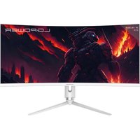
M34-Q-C-PRO - Monitor LC-Power - Free user manual and instructions
Find the device manual for free M34-Q-C-PRO LC-Power in PDF.


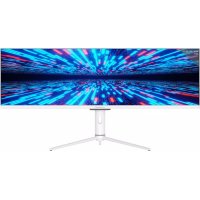
| Product type | Curved LCD monitor |
| Brand | LC-Power |
| Model | M34-Q-C-PRO |
| Screen size | 34 inches (86.36 cm) |
| Resolution | 3440 × 1440 pixels (UltraWide QHD) |
| Refresh rate | 165 Hz |
| Contrast ratio | 3000:1 (typical) |
| Viewing angle | 178° horizontal / 178° vertical |
| Display colors | 16.7 million |
| Pixel pitch | 0.23175 mm (H) × 0.23175 mm (V) |
| Connectivity | DisplayPort (recommended), HDMI, audio jack (headphone output) |
| Power supply | External power adapter: input 100-240 V AC, output 24 V DC, 7 A |
| Dimensions (with stand) | 811.8 × 292 × 524.5 mm |
| Dimensions (without stand) | 811.8 × 115.2 × 366.6 mm |
| Net weight | Approximately 7.4 kg |
| Ergonomic adjustments | Tilt: -5° to +20°; Swivel: ±20°; Pivot: ±5°; Height: 90 mm |
| Wall mount | VESA compatibility (dimensions not specified – standard 100×100 mm probable) |
| Care and cleaning | Unplug before cleaning; use a soft, slightly damp cloth; avoid solvents, benzene, ammonia |
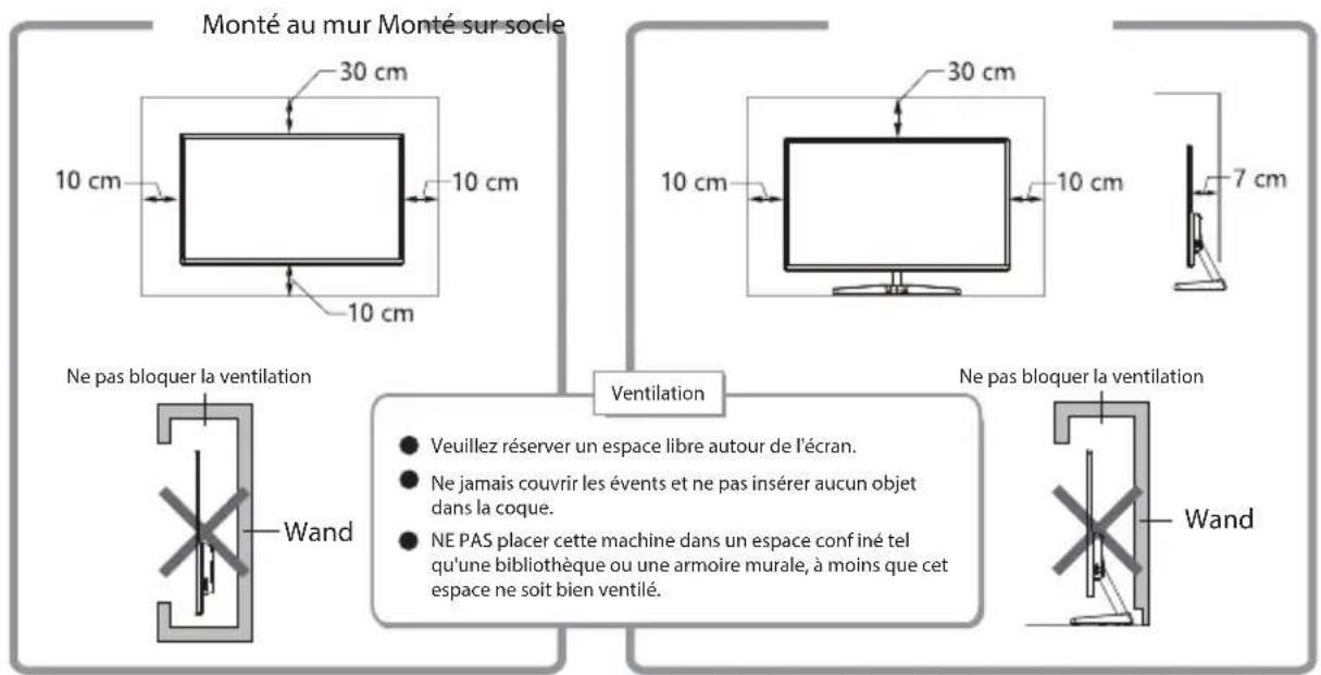
| Safety | Keep away from water and heat sources; do not obstruct ventilation openings; use on a stable surface |
| Spare parts / Repairability | Do not disassemble or repair yourself – contact after-sales service |
Frequently Asked Questions - M34-Q-C-PRO LC-Power
User questions about M34-Q-C-PRO LC-Power
0 question about this device. Answer the ones you know or ask your own.
Ask a new question about this device
Download the instructions for your Monitor in PDF format for free! Find your manual M34-Q-C-PRO - LC-Power and take your electronic device back in hand. On this page are published all the documents necessary for the use of your device. M34-Q-C-PRO by LC-Power.
USER MANUAL M34-Q-C-PRO LC-Power
natural_image
Front view of a modern computer monitor with three tripod stand (no visible text or symbols)USER MANUAL
INHALTSVERZEICHNIS
natural_image
Technical line drawing of a mechanical tool with a base and handle, no text or symbols present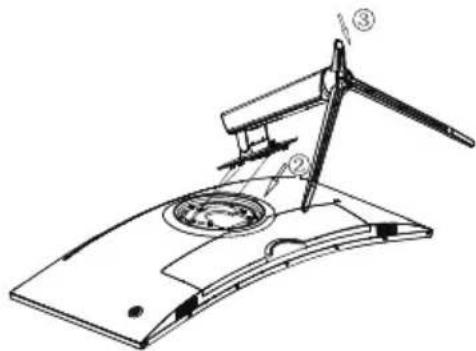
natural_image
Technical line drawing of a mechanical device with a compass and base plate (no text or symbols)natural_image
Technical line drawings of a mechanical device with two views (no text or symbols)natural_image
Technical drawing showing a mechanical assembly with cross-section and top view (no text or symbols)
natural_image
Technical line drawing of a mechanical device with a central shaft and circular component, no text or symbols present
AUDIO AUS DCIN

Schließen Sie
- Safety precautions
- Maintenance
- Product introduction
- Installation
- Wall-mounting installation
- Cable connection
- Display operation
- Basic troubleshooting
- Basic parameters
1.1. Safety precautions S
- Keep the monitor away from water sources or damp places, such as bath rooms, kitchens, basements and swimming pools.
- Make sure the monitor is placed on a flat surface. If the monitor falls down, it may cause injury or a damage to the device.
- Store and use the monitor in a cool, dry and well ventilated place, and keep it away from emission and heat sources.
- Do not cover or block the vent hole in the rear casing, and do not use the product on a bed, sofa, blanket or similar objects.
- The range of the supply voltage of the monitor is printed on the label on the rear casing. If it is impossible to determine the supply voltage, please consult the distributor or local power company.
- If the monitor will not be used for a long period, please unplug it from the electrical outlet.
- Please use a reliable earthing socket, do not overload the socket, or it may cause fire or electric shock.
- Do not put foreign matters into the monitor, or it may cause short circuits resulting fire or electric shock.
- Do not disassemble or repair this product by self to avoid electric shock. If faults occur, please contact the after-sales service directly.
- Do not pull or twist the power cable forcedly.
2. Maintenance
CAUTION: Unplug the power cable from the outlet before cleaning the monitor.
- To clean your screen, slightly moisten a soft, clean cloth with water.
- Please use a special screen-cleaning tissue if possible.
- Do not use benzene, thinner, ammonia, abrasive cleaners or compressed air.
- Inappropriate cleaning solutions may damage the monitor or leave a milky film on the screen or the housing.
- Unplug the monitor if you are not going to use it for a longer time period.
- Do not expose the monitor to dust, liquids or a humid environment.
- In case the monitor gets in touch with any liquid, wipe it down immediately using a dry cloth. In case any liquid gets spilled into the ventilation holes, do not use the monitor anymore. Please contact a professional service technician.
Legal note:

HIGH-DEFINITION MULTIMEDIA INTERFACE
The terms HDMI, HDMI High-Definition Multimedia Interface, HDMI Trade Dress and the HDMI Logos are trademarks or registered trademarks of HDMI Licensing Administrator, Inc.
3. Product introduction
Packing list
- Please check that the package of the monitor contains all parts. If any part is missing, please contact your retailer.
- Note: Additional screws may be used as spare parts. Display/ base parts and screws/DP cable/ power adapter/user manual
4. Installation
Installation of the base:
- Mount the base to the stem and fix it with two screws (1).
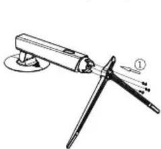
- Tilt the stem into the opening on the back of the monitor housing (2) and push it down (3).
natural_image
Technical line drawing of a mechanical device with a base and handle, no visible text or symbols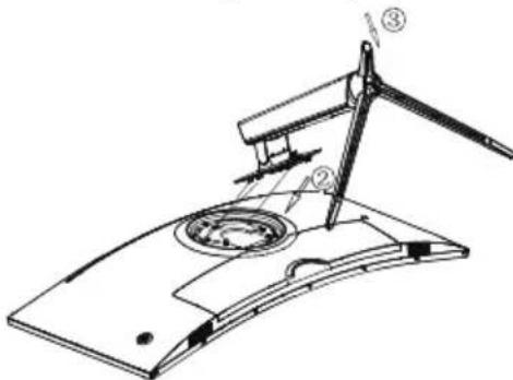
- You have completed the installation.
natural_image
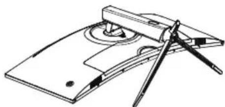
Technical line drawing of a mechanical device with a compass and base plate (no text or symbols)Deinstallation of the base (e.g. if you want to change to wall-mounting):
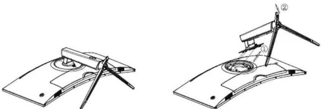
- Push the slider next to the VESA cover of the base upward (1) and tilt the stem upward (2).
natural_image
Technical line drawings of a mechanical device with two views (no text or symbols)- Remove the stem from the back side of the monitor.

Note: Do not press on the liquid crystal screen with hand your to avoid damage to the screen panel.
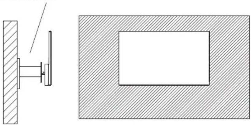
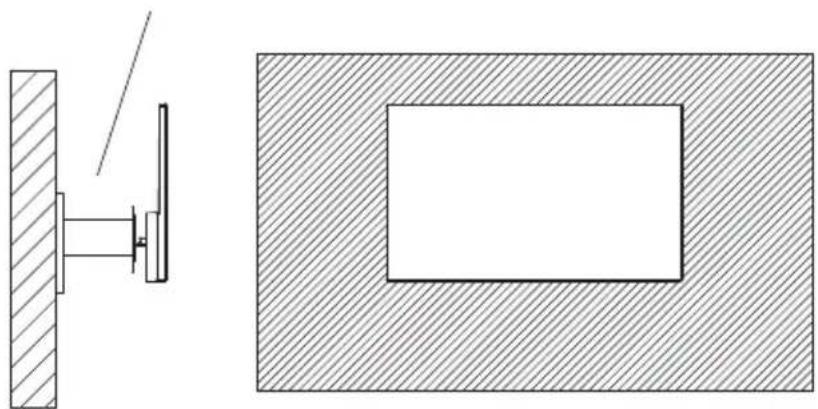
- Take out the wall mount assembly and lock the wall mount assembly with screws.
- Note: Hang the assembled product on a hard wall. Do not pinch the screen with your hands to avoid damaging the screen.
Mount (not supplied)
natural_image
Technical drawing showing a mechanical assembly with cross-section and top view (no text or symbols)
Note: In order to prevent the monitor from falling when it is used on the wall, please install it properly and securely. Do not place or hang any objects on the wall bracket.
6. Cable connection
Note: If the power cable or signal cable is damaged, you must replace it immediately.
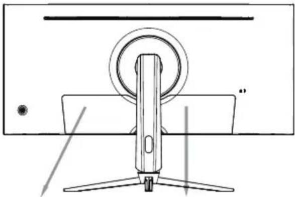
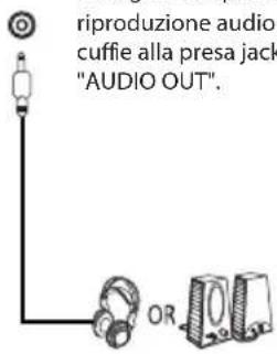
Use a DisplayPort (preferred) or HDMI cable to connect your monitor to the graphics card output of your computer.
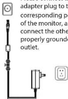
Connect the power adapter to the power connector of your monitor.
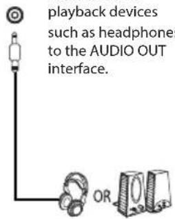
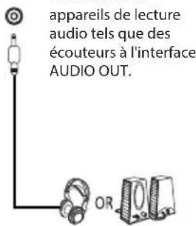
You may connect headphones or speakers to your monitor.
natural_image
Technical line drawing of a mechanical device with a central shaft and circular head (no text or symbols)
AUDIO OUT DCIN
7. Display operation
7.1 Indicator light
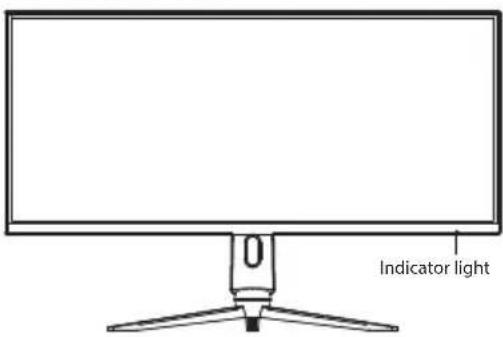
Steady blue light indicates that the power is on and themonitor works normally.
Rod blinking light indicatos that the monitor is in its energy saving mode until it receives a new signal from the computer.
If the monitor is fully turned off, the indicator light will also be turned off.
Please make sure your computer is turned on and operates normally, check if all video cables are fully plugged in and/or connected to the monitor.
7.2 Rocker switch /OSD menu
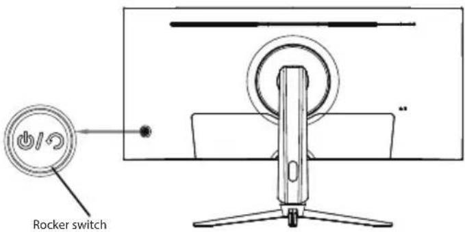
Basic function:
| Rocker switch up | Signal source input |
| Rocker switch down | Volume adjustment shortcut key |
| Rocker switch left | GamePlus shortcut key |
| Rocker switch right | Preset shortcut key |
| Press rocker switch | Press briefly to turn on the machine / Open menu / Press and hold for 3 seconds to turn off the monitor |
Entering the function menu:
| Rocker switch up | Adjust value |
| Rocker switch down | Adjust value |
| Rocker switch left | Return to the previous menu |
| Rocker switch right | Enter to the next menu |
| Press rocker switch | Press briefly to close the menu / Press and hold for 3 seconds to turn off the monitor |
7.3 Panel protection
When the video signals provided by the computer exceed the frequency range of the display, the horizontal and field synchronizing signals will be shut down to protect the display. Set the output frequency of the computer to a lower value within the range of the monitor.
7.4 Monitor adjustment
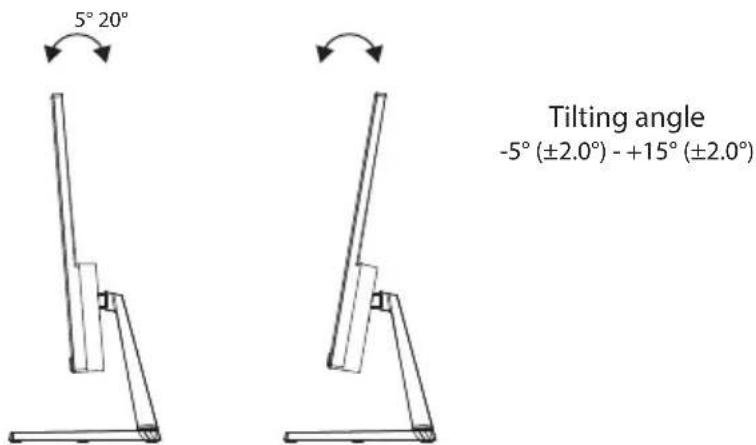
8. Basic troubleshooting
| Issue | Troubleshooting |
| No display/the power indicator LED is off | Check if all cables are connected correctly (power and video signal) and if the monitor has been fully shut down. |
| Blurry image, wrong size | Enter the menu ,image settings" and select „Auto image adjust". |
| Dark image Enter the menu ,Brightness and contrast" to adjust the according values. | |
| Overheated monitor | Leave at least 5 cm (better 10 cm) free space for ventilation around the monitor, do not cover the housing of the monitor. |
| Dark or light spots afterturning the monitor on | The backlight may be illuminated unevenly due to temperature differences at start-up. It may take up to 20 minutes, then the dark/light spots of the display will be corrected automatically. |
| Blinking, shaking or distorted image | Check your computer's display setting and correct the resolution and refresh rate. |
| Unknown sound after turning off the monitor | This may happen when the power-related components of the monitor discharge after turning it off. |
9. Basic parameters
| Product type | Liquid Crystal Display | |
| Product model | LC-M34-Q-C-PRO | |
| Screen size | 34"/86,36 cm | |
| Aspect ratio | 21:9 | |
| Viewing angle | 178° (H) /178° (V) | |
| Pixel pitch | 0,23175 mm (H) × 0,23175 (V) mm | |
| Contrast ratio | 3000:1 (typ) | |
| Colori | 16,7 M | |
| Resolution | 3440 × 1440 Pixel | |
| Maximum refresh rate | 165Hz | |
| Power specifications | DC 24 V = 7 AThe standard voltage and current may vary with countries, please refer to the label at the back of the product. | |
| Product dimensions | Without base | 811,8 × 115,2 × 366,6 mm |
| With base | 811,8 × 292 × 524,5 mm | |
| Net Weight | approx. 7,4 kg | |
| Gross Weight | approx. | |
| Tilting angle | Forward tilting:-5°; backward tilting: 20° | |
| Rotation angle | ±20° | |
| Height angle | 90mm | |
| Pivot angle | ±5° | |
| Environmental conditions | Usage | Temperature: 0°C ~ +40°C humidity: 20% ~ 85% altitude: ≤5000m |
| Storage | Temperature: -10°C ~ 60°C humidity: 10% ~ 90% | |
TABLEDES MATIÈRES
natural_image
Technical line drawing of a mechanical device with a flatbed base and two angled components (no text or symbols)natural_image
Technical line drawings of a mechanical device with two views (labeled ① and ②), showing assembly or assembly steps without any text or symbols.5. Installation murale
Support (non fourni)
natural_image
Technical drawing showing a mechanical assembly with a side view and a cross-sectional view (no text or symbols)
natural_image
Technical line drawing of a mechanical device with a central shaft and circular component, no text or symbols present
AUDIO AUS DCIN
natural_image
Technical line drawing of a mechanical device with a base and lever, no visible text or symbols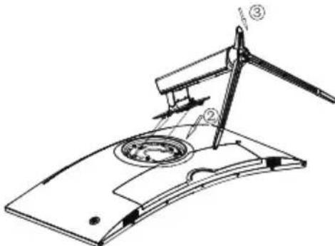
natural_image
Technical line drawing of a mechanical device with compass and base plate (no text or symbols)natural_image
Technical line drawings of a mechanical device with two views (labeled ① and ②), showing assembly or assembly steps without any text or symbols.natural_image
Technical drawing showing a mechanical assembly with cross-section and top view (no text or symbols)
natural_image
Technical line drawing of a computer monitor with a circular button and three legs (no text or symbols)
Presa Jack "AUDIO OUT" DCIN
natural_image
Technical line drawing of a mechanical tool with a base and handle, no visible text or symbols
natural_image
Technical line drawing of a mechanical device with a compass and baseplate (no text or symbols)natural_image
Technical line drawing of a mechanical device with a flat base and stand (no text or symbols)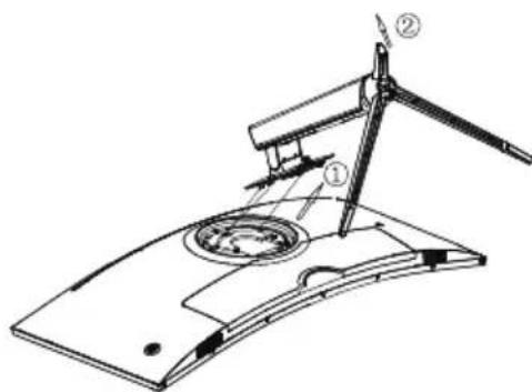
natural_image
Technical line drawing of a mechanical device with a central shaft and circular component, no text or symbols present
- INHALTSVERZEICHNIS
- AUDIO AUS DCIN
- Safety precautions S
- Maintenance
- Product introduction
- Packing list
- Installation
- Installation of the base:
- Cable connection
- AUDIO OUT DCIN
- Display operation
- Indicator light
- Rocker switch /OSD menu
- Basic function:
- Entering the function menu:
- Panel protection
- Monitor adjustment
- Basic troubleshooting
- Basic parameters
- TABLEDES MATIÈRES
- Installation murale
- Presa Jack "AUDIO OUT" DCIN
Brand : LC-Power
Model : M34-Q-C-PRO
Category : Monitor