Stagger - Remote control toy Reely - Free user manual and instructions
Find the device manual for free Stagger Reely in PDF.


User questions about Stagger Reely
0 question about this device. Answer the ones you know or ask your own.
Ask a new question about this device
Download the instructions for your Remote control toy in PDF format for free! Find your manual Stagger - Reely and take your electronic device back in hand. On this page are published all the documents necessary for the use of your device. Stagger by Reely.
USER MANUAL Stagger Reely
GB Operating Instructions
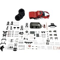
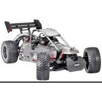
1:10 electric buggy "Stagger" 4WD kit
Item No. 2347928 Page 36 - 69
© Notice d'emploi
text_image
Technical diagram of a vehicle chassis with labeled components A and B, showing mechanical parts and a directional arrow indicating rotation.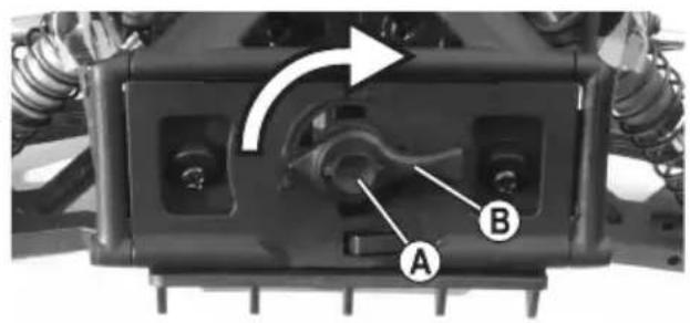
text_image
Technical diagram of a vehicle chassis with labeled components A and B, showing mechanical assembly and directional arrow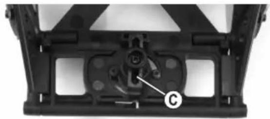
natural_image
Mechanical component with labeled part 'C' and mounting bracket (no readable text or symbols beyond label)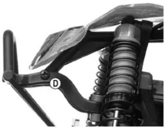
natural_image
Close-up of a mechanical suspension system with visible springs and a handle (no text or symbols)natural_image
Two black L-shaped metal bars labeled D and E, shown side by side (no additional text or symbols)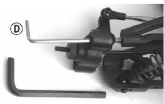
natural_image
Close-up of mechanical components including a spring and wrench, with no visible text or symbols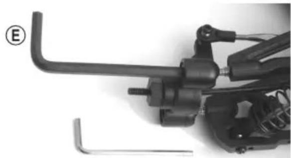
natural_image
Close-up of a mechanical assembly with tools and components (no visible text or symbols)Einstelloptionen:
natural_image
Mechanical assembly diagram showing a spring-loaded component with labeled parts A and B (no text or symbols beyond labels)natural_image
Simple diagram of a vertical structure with four wheels and two top-mounted blocks, labeled 'A' at the top (no text or symbols on the diagram itself)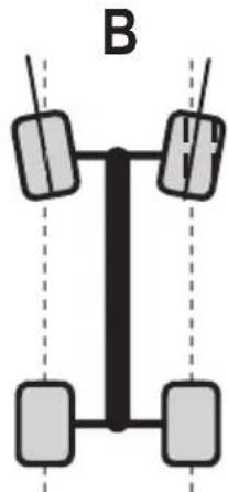
natural_image
Diagram of a vertical vehicle with four wheels and two side-mounted sensors, labeled 'B' (no text or symbols on the diagram itself)
natural_image
Mechanical assembly diagram showing spring and connecting components labeled A and B (no text or symbols beyond labels)natural_image
Mechanical assembly diagram showing suspension system components labeled A, B, and C (no text or symbols beyond labels)Vorderachse
natural_image
Mechanical assembly diagram showing a car suspension system with labeled components (A, B, C), no text or symbols present.Hinterachse
text_image
Technical diagram of a mechanical assembly with labeled parts A, B, C, and D, showing bolted connection details.
natural_image
Close-up of mechanical components with labeled parts (A, B, C, D) and a threaded component, no readable text or symbols beyond labels.text_image
Technical diagram of a mechanical assembly with labeled parts A and B, showing internal components and mounting hardware.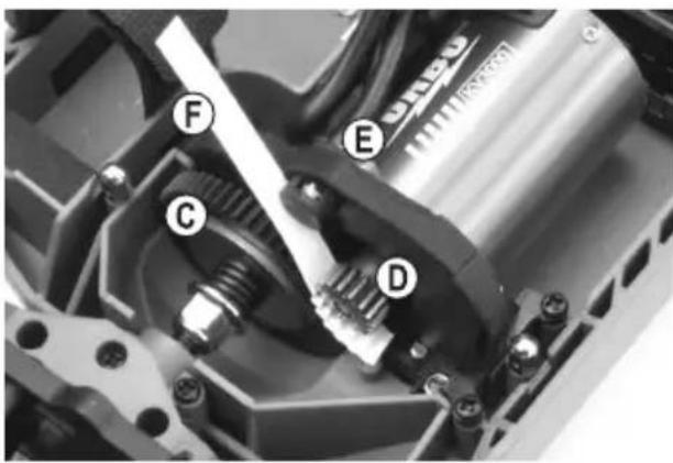
text_image
Technical diagram of a mechanical assembly with labeled parts C, D, E, and F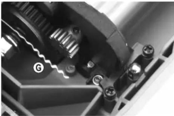
natural_image
Close-up of mechanical gear and housing components (no visible text or symbols)
natural_image
Close-up of a mechanical gear assembly with visible gears and mounting holes (no text or symbols)
- Introduction......37
- Description of symbols....37
- Intended use....38
- Delivery content....38
- Required accessories 39
- Safety information....40
a) General information....40
b) Assembly 41
c) Operation....41
- Battery information....43
- Assembling the model vehicle 44
- Operating the model vehicle....55
a) Opening/removing the body 55
b) Inserting the drive battery in the vehicle....56
c) Setting the remote control and speed controller....56
d) Configuring the camber 57
e) Configuring the wheel alignment 59
f) Adjusting the shock absorbers 60
- Getting started 61
- Cleaning and care....62
a) General information....62
b) Before and after each use 62
c) Changing a tyre 63
d) Adjusting the backlash....64
e) Adjusting the friction clutch....65
- Disposal....66
a) Product 66
b) (Rechargeable) batteries....66
- Troubleshooting....67
- Specifications....69
1. Introduction
Dear customer,
Thank you for purchasing this product.
This product complies with statutory, national and European regulations.
To ensure that the product remains in this state and to guarantee safe operation, always follow the instructions in this manual.

These operating instructions are part of this product. They contain important information on setting up and using the product. Do not give this product to a third party without the operating instructions. Therefore, retain these operating instructions for reference!
All company and product names contained herein are trademarks of their respective owners. All rights reserved.
If there are any technical questions, please contact: www.conrad.com/contact
2. Description of symbols

The symbol with an exclamation mark in a triangle is used to highlight important information in these operating instructions. Always read this information carefully.

The arrow symbol indicates special information and tips on how to use the product.
3. Intended use
The “Stagger” buggy is an electrically driven model vehicle that is wirelessly controlled with a suitable remote control (not included). For operation of the model vehicle, various accessories are required that are not included and must be ordered separately (see section 5).
The model vehicle is intended exclusively for private use in the model making sector with the associated operation times.
The model is primarily intended for outdoor use, but it can also be used in suitable indoor spaces.
This product is not suitable for children under 14 years of age.

Always follow the safety information in these operating instructions. They contain important information on how to use the product safely.
You are solely responsible for the safe operation of this model!
4. Delivery content
- Vehicle kit
- Assembly instructions
- Operating instructions
Up-to-date operating instructions
Download the latest operating instructions at www.conrad.com/downloads or scan the QR code shown. Follow the instructions on the website.

5. Required accessories
The “Stagger” buggy is supplied as a kit and must be assembled before the first use. For this purpose, the kit also comes with separate assembly instructions with many assembly drawings. These instructions contain important tips and recommendations for proper assembly of the model.

Important!
vidual parts found in the respective assembly drawings are packed separately. Only open the bags just before assembling the parts.
For assembly, you can use standard tools such as a screwdriver, needle-nose pliers or a hexagon socket wrench. However, you should always use suitable screwdrivers to avoid damaging the screw heads during assembly.

Practical tips:
A model vehicle stand has proven itself an effective aid in assembling the vehicle (especially for subsequent assembly steps). In addition to easy assembly, the stand can be used later for trial runs of the drive mechanism or for maintenance purposes.
For operation of the model vehicle, the following accessories are required that are not included and must be ordered separately:
- Remote control with transmitter and receiver (at least 2 channels)
• Steering servo (recommended: min. 4 kg) - Electric motor (recommended: Brushed electric motor, type 550, 13 turns or brushless electric motor, type 3652, 3000 KV)
- Speed controller (recommended: 40 A continuous current, depending on the motor used)
- Drive battery (recommended: Racingpack version, LiPo or NiMH, depending on the speed controller/motor used)
- Batteries or rechargeable batteries for the remote control
- Suitable charger for transmitter and drive rechargeable batteries
For best results, we also recommend the following components:
- Spare tyres (in order to quickly change worn/damaged tyres)
- Compressed air spray for cleaning
- Thread-locking fluid
- Carry bag

Damage caused due to failure to observe these operating instructions will void the warranty. We shall not be liable for any consequential damage!
We shall not be liable for damage to property or personal injury caused by incorrect handling or failure to observe the safety information! Such cases will void the warranty/guarantee.
The guarantee and warranty do not apply to normal wear and tear during operation (such as worn tyres or worn gears) and accidental damage (such as broken chassis parts or steering knuckle).
Dear customer,
These safety instructions are designed to ensure the safe operation of the product and your personal safety. Read this section very carefully before using the product!
a) General information
Caution, safety hazard!
This model has the potential to cause damage to property and/or individuals. Ensure that you are sufficiently insured, e.g. by taking out private liability insurance.
If you already have a policy, check with your insurance company that use of this model is covered by the policy.
- The unauthorised conversion and/or modification of the product is not allowed for safety reasons. Only use original spare parts for repairs.
• This product is not a toy and is not suitable for children under 14 years of age. - The product must not be used in wet or damp environments to prevent corrosion or rusting of metal parts. If the product features a moisture-proof steering servo or a corresponding speed controller, the requisite protection of the electric motor or the drive battery and connectors must also be considered. Moisture ingress into the drive battery can cause fire or explosion!
- Do not leave packaging material lying around carelessly, because it could become a dangerous plaything for children.
- If you have any questions that are not answered by these operating instructions, contact us (see section 1 for contact information) or an experienced technician.
- You must learn how to operate and handle remote-controlled model vehicles before actually using them! If you have never steered such a vehicle, drive especially carefully and get used to the vehicle's responses to the remote control commands first. Be patient!
- Do not take any risks when using the product! Always use the model responsibly, otherwise you may endanger yourself and your surroundings.
- Occasional maintenance work and repairs are required to ensure safe use. For example, the tyres may become worn, or some parts may be damaged due to driver error.
Only use original spare parts for maintenance and repair work!

b) Assembly
- During vehicle assembly, there is a risk of injury due to sharp edges, pointed parts and improper handling of tools.
- Improper assembly may result in damage to vehicle parts and poor performance. So be very careful when assembling.
- To assemble the vehicle, use only a sufficiently large, flat, and stable surface. Protect the surface of a work table from scratches by using a suitably thick underlay.
- Do not use force when assembling parts. Do not overtighten the screws! However, make sure that screws, nuts, etc. are tightened correctly.
- For assembly, use suitable tools in excellent condition.
• Take your time! - If you have never assembled such a vehicle before, seek guidance from an experienced fellow model maker. A few helpful tips and assistance from a professional can easily solve many problems, especially at the beginning of a “model making career”.
c) Operation
- We recommend that you use a latter-day 2.4 GHz remote control. However, if you are still using an older generation 27 or 40 MHz remote control to operate the model, make sure before every use that no other models are operated on the same frequency within the range of the remote control. Control over the remote controlled vehicle will be lost! Always use different frequencies for each model.
- With every operation, the settings of the trim regulator for forward/reverse drive as well as those for steering must be checked, and if necessary, modified.
For this reason, the wheels of the vehicle must not be put on the ground during setup (switching on the remote control and the vehicle). Place the vehicle on a suitable surface so that the wheels can turn freely (do not touch the drive!).
Then adjust the trim accordingly so that when the lever for the forward/reverse drive (neutral position) is fully released, the motor stops rotating or the steering is straight (straight drive can accurately be adjusted later while operating the vehicle).
- During setup, always switch on the remote control (transmitter) first. Only then can the rechargeable battery pack of the vehicle be connected with the cruise control/receiver and the model be switched on. Otherwise there may be unexpected responses by the cruise control/receiver and therefore the electric model!
- Improper use can cause serious injury and damage to property! Only use the vehicle when it is within your sight. Do not use the vehicle at night.
- Only use the vehicle when you are fully alert and able to respond. As is the case when driving a real vehicle, fatigue, alcohol or medications can affect your ability to react.
- Please note that this model vehicle should not be driven on public roads or streets. Only operate it on private sites or places which are specifically designated for remote-controlled models.
- Driving a model on a model racing/rally track requires prior permission of the owner.
- Do not drive the vehicle towards people or animals!

- Do not drive the vehicle in the rain or through wet grass, water, mud or snow. Since the model is neither water-resistant nor waterproof, corrosion or rusting of its metal parts can result if it is exposed to moisture or humidity. If the product features a moisture-proof steering servo or a corresponding speed controller, the requisite protection of the electric motor or the drive battery and connectors must also be considered. Moisture ingress into the drive battery can cause fire or explosion!
- Also avoid driving at very low outdoor temperatures. Cold temperatures can cause the plastic on the chassis to lose its elasticity. In this case, even small accidents may damage the model.
- Do not use the vehicle during thunderstorms, under high-voltage power lines or next to radio masts.
- Do not take any risks when using the product! Always use the model responsibly, otherwise you may endanger yourself and your surroundings.
- Always keep the remote control (transmitter) turned on when the model is in use. To stop the vehicle, always turn the vehicle off first and then separated the rechargeable battery pack from the cruise control/receiver, only after that can the remote control be turned off.
- Before using the model, check whether it responds properly to the remote control commands.
- When there are weak batteries (e.g. rechargeable batteries) in the remote control, the range decreases. When the drive rechargeable battery is weak, the vehicle gets slower or no longer responds correctly to the remote control.
If this is the case, stop operation immediately. Then replace the batteries/rechargeable batteries in the remote control with new ones, or recharge the rechargeable batteries in the vehicle or the remote control.
- The motor and drive as well as the speed controller and the vehicle's battery pack get hot during operation. Before replacing or recharging the rechargeable batteries, always wait at least 5 to 10 minutes for all parts to cool down.
- Do not touch the motor, the speed controller or the rechargeable battery until they have cooled down. Burn hazard!
7. Battery information

Although batteries and rechargeable batteries are very useful in our everyday life, nevertheless they present numerous safety hazards.
Therefore, always observe the following general information and safety instructions when handling batteries and rechargeable batteries. Always observe all additional safety instructions and information provided by the manufacturer/distributor of the drive battery or charger you are using.
- Keep batteries/rechargeable batteries out of reach of children.
- Do not leave batteries/rechargeable batteries lying around, as they present a choking hazard for children and pets. Seek immediate medical advice if a battery is swallowed!
- Batteries/rechargeable batteries must never be short-circuited, disassembled or thrown into fire. This may cause an explosion!
- When handling leaking or damaged batteries/rechargeable batteries, always use suitable protective gloves to avoid burning your skin.
- Do not recharge regular batteries. This may cause a fire or explosion! Only charge rechargeable batteries which are intended for this purpose (1.2 V); use suitable battery chargers. Batteries (1.5 V) are designed to be used once and must be disposed of properly when they are empty.
- Observe the correct polarity when inserting batteries (observe plus/+ and minus/−). Incorrect polarity will not only damage the transmitter and batteries, It may also cause a fire or explosion.
- If you do not plan to use the model for an extended period (e.g. during storage), remove the batteries from the remote control to prevent them from leaking and causing damage. Disconnect the drive battery from the speed controller.
- Rechargeable batteries should be charged at least once every 3 months to prevent damage due to deep discharge, which will render them useless.
- Always replace the entire set of batteries or rechargeable batteries. Do not mix full batteries/rechargeable batteries with half-full ones. Always use batteries or rechargeable batteries of the same type and from the same manufacturer.
- Never mix batteries with rechargeable batteries! The remote control can be powered with disposable or rechargeable batteries.
- Never charge the drive rechargeable battery immediately after use. Always let the drive rechargeable battery cool down until it has reached room or ambient temperature again.
- Only charge intact and undamaged drive rechargeable batteries. Do not charge the rechargeable battery if the external insulation of the rechargeable battery is damaged, or if the rechargeable battery is deformed or swollen. In this case there is serious danger of fire and explosion!
- Protect the outer shell of a rechargeable battery from damage and do not pierce it with sharp objects. This may cause a fire or explosion!
- Never recharge the drive battery unattended.
- Disconnect the charging cable or charger from the drive battery when it is fully charged.
8. Assembling the model vehicle
You will need the following tools for assembly:
- Cross-head screwdriver, hexagon socket wrench and socket spanner in different sizes
- Needle-nose pliers
- Wire cutter
- Suitable gear grease
- Thread-locking fluid (medium strength)

Practical tips:
A suitable pad is also recommended for assembly. For example, you may use a universal car floor mat with a grid, allowing optimal arrangement of screws, nuts and other small parts and preventing them from rolling away.
The model is supplied in the form of pre-arranged assemblies with alphanumeric inscriptions.
Some larger bags (for example, bag A) include smaller bags with appropriate alphanumeric inscriptions, for example, A-1 or A-1-1.

Important!
tion to these operating instructions, refer to the separate assembly instructions. The procedure for proper assembly of the model vehicle is shown in clear drawings. These assembly instructions also contain additional information and practical tips for each assembly stage.
A sketch showing specially required screws/nuts etc. with their respective sizes can be found in the assembly instructions. The figure in brackets indicates the quantity of the respective parts. A label for the parts bag required for each assembly stage can be found at the top right of the sketch drawings. To avoid confusion, only open the parts bag that is needed for the assembly stage.
Then check the contents against the sketch and place the components and screws at the respective assembly sites.
Do not go to the next assembly stage and do not open another parts bag until you have assembled all parts from the current assembly stage.
This procedure is the quickest way to assemble the model correctly.

Practical tips:
If the exact assembly of a component cannot be clearly identified from the current drawing, look at the drawings below. The vehicle is often shown from different perspectives, which can make the assembly of different components more clear.
If required, the assembly instructions can also be downloaded as a PDF in our online shop, either under product or in the download centre. Pages can then be enlarged on a monitor and details can be seen more clearly.
Proceeding with the assembly:
Assembly instructions, figure 1 (A-1):
The two plastic parts for the rear bumper are to be connected with two M3 x 16 screws.
Assembly instructions, figure 2 (A-2):
Mount the rear bumper on the aluminium base plate using two M3 x 10 countersunk screws.
Assembly instructions, figure 3 (A-3):
Clip a snap ring onto each of the two thin metal axles using needle-nose pliers. Then assemble the lower suspension arm, paying attention to the orientation of the components (the left and right suspension arms have identical structure). Finally, clip the two remaining snap rings onto the ends of the two metal axles.
Assembly instructions, figure 4 (A-4):
Place the lower suspension arm on the aluminium base plate (it only fits in one orientation, with 2 lugs on the underside of its central part fitting exactly into the aluminium base plate). Fasten the lower suspension arm on the aluminium base plate using four M3 x 15 countersunk screws. Finally, secure the screws with four M3 locking nuts.
Assembly instructions, figure 5 (B-1):
Fasten the two plastic parts together using one M3 x 8 screw. Figure 5 shows the components of the pre-assembled friction clutch.
Assembly instructions, figure 6 (B-2):
Unless preset, set the 7 – 7.5 mm gap between the nut and the pressure washer for the friction clutch. After that assemble the parts as shown in the figure. Pay attention that ball bearings (a smaller one in the retaining plate and two larger ones on the drive axle of the friction clutch) have different sizes.

The adjustment process of the friction clutch is described in section 11. e).

Important!
When attaching and tightening down the cardan shaft attachment, make sure to screw in the M4 x 4 set screw so that it rests on the flattened side of the drive axle.
During assembly make sure that the gear can be turned easily, but there should not be too much play (the gear must not turn too tight either!).
The bevel gear is secured with an M2.5 snap ring on the friction clutch axle. In this case, you will also need needle-nose pliers.
Insert the two M3 nuts into the openings in the motor support plate and fix the lower one with a single M3 x 15 screw (the upper one will later be used during the motor mounting).
Assembly instructions, figure 7 (B-3):
Figure 7 shows the components of the pre-assembled differential. The differential is already pre-greased. When dismantling the differential for maintenance purposes, clean it and add fresh grease (add just sufficient amount of grease, do not fill the differential with grease to the brim!).
Assembly instructions, figure 8 (B-4):
First put one of the two thin metal rings on each of the differential attachments followed by the two ball bearings. Then insert it into the differential housing as well as the pre-assembled friction clutch. Pay attention to the position of the two ball bearings on the friction clutch axle in the differential housing.
→ Use the metal rings to adjust the play between the two gears. The gears should not turn too tight, but there should not be too much play either. The position of the differential can be adjusted with the metal rings, which must be placed between the differential and the ball bearing.
A somewhat thicker metal ring is typically not required. However, in order to achieve an optimal position of the gears, it may be necessary to use several metal rings combined with one another in different ways due to the production tolerances of plastic parts.
Apply a suitable gear grease to the gears (apply just sufficient amount of grease, but do not fill the gear housing to the brim!).
Finally, place the plastic part pre-assembled in figure 5 on the differential housing and secure it with four M3 x 18 screws.
Assembly instructions, figure 9 (C-1):
Insert the motor support plate with the rear axle differential mounted on it into the chassis pan.
→ Our tip:
You may have to loosen the M4 x 4 set screw (see figure 6) that secures the cardan shaft attachment once again so that the differential housing can be correctly inserted into the opening in the chassis pan. Secure the cardan shaft attachment again with the set screw after the motor support plate and differential housing have been screwed tight in the chassis pan.
First secure the differential housing with two M3 x 15 screws in the chassis pan and then the motor support plate with two M3 x 10 screws.
Finally, screw the motor support plate tight to the chassis pan using two M3 x 10 countersunk screws and two M3 locking nuts (a detailed illustration of the underside of the chassis pan and the position of the two countersunk screws can be found in the bottom left of figure 9).
The locking nuts can be easily inserted at the desired location with needle-nose pliers.
Now check whether the main gear (and the associated rear axle differential) can be turned easily. It must not turn tight!
Assembly instructions, figure 10 (C-2):
Fasten the aluminium base plate shown in figure 4 to the chassis pan using four M3 x 10 countersunk screws. Figure 10 shows both the top and bottom view.
Use the remaining six M3 x 10 countersunk screws to screw the differential housing down to the aluminium base plate.
Finally, use a single M3 x 10 round-head screw (it is clearly marked in figure 10) to screw the motor support plate tight from below.
The transparent cover and the remaining screws in bag C-3 are only required in figure 18.
Assembly instructions, figure 11 (D-1):
The figure shows the components of the pre-assembled upper suspension arm.
Important!
The two brass cases “A” and “B” have different widths. In addition, the brass case “A” has a flattened edge and must point in the direction of the steering knuckle/tyre when installing the upper suspension arms (figure 12).
Assembly instructions, figure 12 (D-2):
Screw two 3 x 22 screws into the lower openings of the shock absorber bridge (make sure that the orientation is correct, the flat side of the shock absorber bridge should point towards the motor support plate).
Place the two upper suspension arms (see figure 11) on the 3 x 22 screw. Make sure that the suspension arms are attached with the correct side (brass case "B"), as shown in figure 11.
Then insert the shock absorber bridge from the rear into the differential housing and screw it tight with two M3 x 10 screws.
→ Our tip:
The rear bumper mounted in figure 2 can be temporarily dismantled by unscrewing the two countersunk screws for easier access to the two M3 x 10 screws.
Then insert the shock absorber bridge from the rear into the differential housing and screw it tight with two M3 x 10 screws.
Fasten the reinforcement bracket between the differential housing and the rear bumper using two screws M3 x 12 and M3 x 16 (see figure 12).
Assembly instructions, figure 13 (E-1):
Insert the respective ball bearings in each of the two steering knuckles. Then insert the wheel axles from the inside.
The wheel axle has a hole into which the drive pin is to be inserted. Finally, attach the wheel hub nut in the correct orientation (a slot on one side of the wheel hub nut must exactly match the drive pin). Do not use any force.

Important!
steering knuckles are not structurally identical: one of them is intended for the left axle (L) and the other one for the right axle (R). You can see the difference between the steering knuckles if you look at them from above.
Assembly instructions, figure 14 (E-2):
Fasten each of the two steering knuckles to the lower suspension arm with a respective 3 x 26 screw.

Important!
steering knuckles are not structurally identical: one of them is intended for the left axle (L) and the other one for the right axle (R). Refer to figure 13.
Insert the drive axle between the differential and the wheel axle. Then screw the upper suspension arm tight to the steering knuckle with an M3 x 12 screw. The figure shows which of the 3 openings in the steering knuckle you should use.
Try turning the main gear to check whether the wheel axles turn easily. The drive must not be stiff! Turn the main gear while holding one wheel axle; if the other wheel axle turns, the differential works correctly.
Assembly instructions, figure 15+16 (F):
Four structurally identical shock absorbers are already pre-assembled and filled with oil. The figures show the individual components of a shock absorber.

Our tip:
As is the case with full-size vehicles, the shock absorbers are wearable parts. If too much oil leaks from the lower end of the shock absorber, the seals are defective and must be replaced. As this usually indicates that other parts of the shock absorber are also worn, we recommend that you replace the entire shock absorber.
As is the case with full-size vehicles, both shock absorbers on one axle must always be replaced at the same time to retain the vehicle performance.
Bag F contains various clips for the shock absorbers. They are used to adjust the spring preload. Inserting the clips between the spring and the upper end of the shock absorber makes the suspension “harder” and thus ideal for a smoother road surface. Always insert the same clips on the left and right axles.
Assembly instructions, figure 17 (F-1):
Mount each of the shock absorbers on the left and right rear axles.
Fasten the shock absorber on the upper side to the rear shock absorber bridge with an M3 x 12 screw and a plastic case using the outer holes. The correct position is shown in the detailed figure at the top right.
The lower end of the shock absorber must be inserted into the corresponding opening in the lower suspension arm and then screwed tight with an M3 x 15 screw (using the middle hole). Figure 17 shows the correct installation on the right shock absorber.

Our tip:
The mounting positions on the shock absorber bridge or the lower suspension arm can be changed. However, this should only be done by drivers who can notice the slight change in driving behaviour (caused by different compression of the shock absorbers). The mounting position on the left and right axles must always be the same in all cases.
Assembly instructions, figure 18 (C or C-3):
Fasten the transparent cover for the cardan shaft in the chassis pan.

Important!
Make sure that among the screws there is a countersunk screw, which must be installed in the right place (see figure). Otherwise, not only will the cover be damaged, but the screw protruding further can cause problems during installation of a motor.
Assembly instructions, figure 19 (G-1):
Secure the front bumper bar to the support arm with two M3 x 12 screws.
Assembly instructions, figure 20 (G-2):
Fasten the aluminium base plate to the bumper bar in the correct orientation using two M3 x 10 countersunk screws.
Assembly instructions, figure 21 (H-1):
The figure shows the assembly of the front suspension arms. You will need a 5 mm hexagon socket wrench to screw the plastic set screws into the steering knuckle. Make sure that the plastic set screws are oriented correctly.
First, securely tighten the inserts with care. Then loosen the inserts until the ball heads of the metal screws ("pivot ball" screw) can be moved easily without any play in the bearing.

Important!
The suspension arms must be mounted as shown in figures 21 and 22 such that they fit the left (L) and right (R) side. Since the upper suspension arm is shorter, the pivot ball holders are offset.
Figure 21 shows a detailed view of the left (L) steering knuckle; note the arrow on the small plastic lug.
Use a 2.5 mm hexagon socket wrench to screw the pivot ball screws about 2/3 into the suspension arms, leaving approx. two to three threads exposed. Then, finely adjust the chassis.
→ Two upper and two lower suspension arms use structurally identical plastic parts.
Insert the respective ball bearings in each of the two steering knuckles.
Assembly instructions, figure 22 (H-2):
Clip a snap ring onto each of the two thin metal axles using needle-nose pliers. Then assemble the front suspension arm, paying attention to the orientation of the left and right suspension arms. Finally, clip the two remaining snap rings onto the ends of the two metal axles.
Then insert the wheel axles from the inside. The wheel axle has a hole into which the drive pin is to be inserted.
Finally, attach the wheel hub nut in the correct orientation (a slot on one side of the wheel hub nut must exactly match the drive pin). Do not use any force.
Assembly instructions, figure 23 (H-3):
Place the suspension arm on the aluminium base plate (it only fits in one orientation, with 2 lugs on the underside of its central part fitting exactly into the aluminium base plate).
Fasten the suspension arm on the aluminium base plate using four M3 x 15 countersunk screws. Finally, secure the screws with four M3 locking nuts.
Assembly instructions, figure 24 (I):
The servo saver is already pre-assembled and its components are shown in figure 24 on the left. Mount it using two M3 x 8 countersunk screws. Pay attention to the shape of the holes in the chassis pan and on the underside of the two servo saver axles.
Assembly instructions, figure 25 (J):
Fasten the complete front suspension arm assembly to the chassis pan using five M3 x 10 countersunk screws.
Tighten the M4 x 4 set screw only lightly when assembling the bevel gear unit. The exact position of the cardan shaft holder and the final position are adjusted at the later assembly stage shown in figure 27.

Important!
attaching and tightening down the cardan shaft attachment, make sure to screw in the M4 x 4 set screw so that it rests on the flattened side of the drive axle.
Assembly instructions, figure 26 (K-1):
Fasten the front shock absorber bridge to the upper suspension arm holder with two M3 x 10 screws.
Assembly instructions, figure 27 (K-2):
First put one of the two thin metal rings on each of the differential attachments followed by the two ball bearings. Then insert it and the pre-assembled bevel gear unit shown in figure 25 into the differential housing (first loosen the M4 set screw on the cardan shaft holder). Pay attention to the position of the two ball bearings on the bevel gear unit axle in the differential housing.

Use the metal rings to adjust the play between the two gears. The gears should not turn too tight, but there should not be too much play either. The position of the differential can be adjusted with the metal rings, which must be placed between the differential and the ball bearing.
A somewhat thicker metal ring is typically not required. However, in order to achieve an optimal position of the gears, it may be necessary to use several metal rings combined with one another in different ways due to the production tolerances.
Apply a suitable gear grease to the gears (apply just sufficient amount of grease, but do not fill the gear housing to the brim!).
Install the upper differential housing. Finally, attach the part installed in figure 26 and fix it using the four M3 x 18 screws; then screw in the M3 x 8 screw at the rear in the middle of the cover.
Then secure the cardan shaft holder with the M4 set screw.
Finally, insert one of the small rubber rings into the drive axle.
Assembly instructions, figure 28 (K-3):
First insert the main cardan shaft into the recess. Then insert the front differential into the chassis and screw tight with four M3 x 10 countersunk screws.
After that, screw the differential housing to the support arm of the front bumper bar using two M3 x 15 screws.
Insert the drive axle between the differential and the wheel axle. Then screw each of the two upper suspension arms to the suspension arm holder using the long screws.
Try turning the main gear to check whether all four wheel axles turn. The drive must not be stiff!
Assembly instructions, figure 29 (F):
Mount each of the shock absorbers on the left and right front axles.
Fasten the shock absorber on the upper side to the front shock absorber bridge with an M3 x 12 screw and a plastic case using the outer hole.
The lower end of the shock absorber must be inserted into the corresponding opening in the lower suspension arm and then screwed tight with an M3 x 15 screw (using the outer holes). A detailed illustration of the correct position of the shock absorber in the suspension arm is shown at the bottom right in figure 29.

Our tip:
The mounting positions on the shock absorber bridge or the lower suspension arm can be changed. However, this should only be done by drivers who can notice the slight change in driving behaviour (caused by different compression of the shock absorbers). The mounting position on the left and right axles must always be the same in all cases.
Assembly instructions, figure 30 (L-1):
Assemble the two steering rods. Check in advance whether both steering rods have the same length. Only then will both wheels have the same track setting.

Important!
The conical part of the brass bearing must be oriented to the steering arm (see detailed view in figure 30). One of the sides of the brass bearing at the other end of the steering arm is flattened and points towards the plastic steering rod (not towards the nut).
Assembly instructions, figure 31 (L-2):
Before installing the steering servo (not included), be sure to select the matching steering lever for the servo. One of the three supplied levers can be mounted depending on the servo shaft gearing. Alternatively, you can use a lever of suitable length that comes with the servo.

Important!
The servo lever must be installed at an angle of 90^ when the steering (and thus also the servo) on the transmitter is in the middle position. To do this, power up the remote control and check the middle position of the steering servo.
After installing the servo, clip the steering linkage onto the ball head screw.
Assembly instructions, figure 32 (M):
Figure 32 shows the assembly of the receiver box. Use the two clips to seal the box cover. Screw the M3 x 3 set screw into the socket of the antenna tube to secure the antenna tube (if the receiver you are using has a longer antenna cable). The holder for the antenna tube is located on the right-hand side of the receiver box when viewed in the direction of travel.
Assembly instructions, figure 33 (N-1):
With the motor plate (not included) attached to the motor, you can now mount the motor pinion on the motor shaft. Do not fully tighten the M3 x 3 set screw yet, because you may still need to move the gear on the motor shaft so that it runs exactly on the main gear.

Important!
attaching and tightening down the motor pinion, make sure to screw in the set screw so that it rests on the flattened side of the motor shaft.
Assembly instructions, figure 34 (N-2):
First, mount the fixing screw at the bottom of the motor plate and then install the upper screw. If necessary, move the motor pinion on the motor shaft such that both gears are meshed throughout the width. Then securely tighten the motor pinion.

Backlash adjustment is described in section 11. d) and must be carried out before the vehicle is used for the first time.
Assembly instructions, figure 35 (O):
Screw two retaining screws for the gearbox cover into the corresponding holes in the chassis pan. The holes in the top of the screw head must be parallel to the longitudinal axis of the vehicle (otherwise you will not be able to insert the clips). Then put on the gearbox cover and secure with the two clips.
Clip two plastic clips onto the retaining screw in front of the upper suspension arm. Attaching the clips at the back reduces the castor angle and thus compromises the directional stability.
Finally, screw four M3 x 3 set screws into the corresponding openings in the upper suspension arm holder. Make sure that the four suspension arm screws are firmly tightened and cannot get loose.

For clarity, two detailed illustrations show the position in which the set screws must be screwed in.
Assembly instructions, figure 36 (P):
Mount the four tyres on the vehicle. As they have identical structure, their is no particular position in which they should be mounted. When attaching the wheels, make sure that the hexagon on the inside of the rim rests exactly on the wheel hub nut. Do not use excessive force when tightening the wheel nuts.
Assembly instructions, figure 37 (Q):
Use a double-sided adhesive tape to attach a suitable speed controller (not included) in front of the motor installed.
Use the included hook-and-loop straps to fix the rechargeable battery, guiding them through the corresponding openings in the chassis pan.
Put the receiver you are using in the receiver box with foam inserts protecting it from vibrations while driving.
The cables between the receiver and the steering servo or speed controller are guided out of the receiver box on the edge protected with a foam insert, just like the antenna (unless the receiver you are using has an integrated antenna).
All cables should be laid in such a way that they cannot get into moving drive parts. Fix the cables with cable fasteners.
Assembly instructions, figure 38 (R-1):
The lock for the roll cage must be attached as shown in the figure.

Important!
essential to ensure that the rotary knob and the lock are put together correctly; the flattened sides must fit together, as shown in the detailed illustration.
Assembly instructions, figure 39 (R-2):
Secure the handle to the rotary knob with two M2.5 x 6 screws. Ensure the correct orientation in order to be able to later swivel the handle by 90° between the two lock symbols on the plastic surface ("locked" or "unlocked"). More information can be found in section 9. a).
Assembly instructions, figure 40 (S-1):
Use the two M2.5 x 15 screws to mount the two brackets on the front part of the roll cage.
Assembly instructions, figure 41 (S-2):
Assemble the roll cage. The two M2.5 x 12 screws are specially marked in the figure, since all other twelve screws have the same size - M2 x 15.
Assembly instructions, figure 42 (S-3):
Secure the last part of the roll cage using two M2.5 x 15 screws.
Assembly instructions, figure 43 (T):
Mount the body parts on the roll cage. Make sure to use a washer for the two screws on the left and right at the rear (the screws on the right-hand side are not shown, but must also be secured).
Assembly instructions, figure 44 (U-1):
The LED bar is already pre-assembled and its components are shown in figure 44.
Assembly instructions, figure 45 (U-2):
Secure the LED bar to the body with two M2.5 x 12 screws. The power is supplied via the plug connected to a free socket on the receiver (pay attention to correct polarity when plugging in). The cable can be fixed to the roll cage using suitable cable fasteners.
Assembly instructions, figure 46 (V-1):
Fasten the two helmets to the dummy driver with two M3 x 8 screws.
Assembly instructions, figure 47 (V-2):
Fix the dummy driver to the body using four M2.5 x 8 screws.
Assembly instructions, figure 48 (V-3):
Now attach the complete body to the front of the chassis using two screws. Then snap shut the body and lock it with the rotary knob.
9. Operating the model vehicle
a) Opening/removing the body
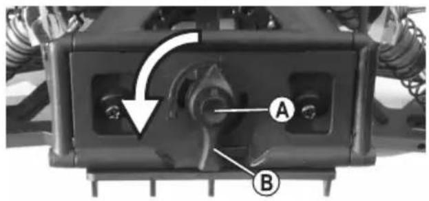
The body can be folded up to engage the drive battery or for adjustments to the speed control. For this purpose, there is a special quick lock at the rear of the vehicle.

Do not overtighten the quick lock. Do not use force when opening and closing.
Open the body
- Press and hold the round knob (A) in the middle of the quick lock and turn the outer handle (B) 90° counterclockwise (to the left).
- Release the button.
• The body can then be folded upwards.
Close the body
- Fold the body upwards.
- Press and hold the round knob (A) in the middle of the quick lock and turn the outer handle (B) 90° clockwise (to the right).
- Release the button.
Set the locking bolt
If the quick lock does not open or close properly, check that the locking latch (C) has released inside or is twisted.
The locking bolt (C) must be oriented so that it is at a 90° angle to the handle (B). Only then can the quick lock be released and closed.
Disassemble the body
The articulation between the vehicle and the body can be very easily removed by unscrewing two screws (D) on the front of the vehicle (one screw each on the left and right).

Warning!
ble to the LED light bar is located be-
tween the body and the chassis. Remove the body very carefully so as not to damage the cable!
text_image
Technical diagram of a vehicle chassis with labeled components A and B, showing mechanical parts and a directional arrow indicating rotation.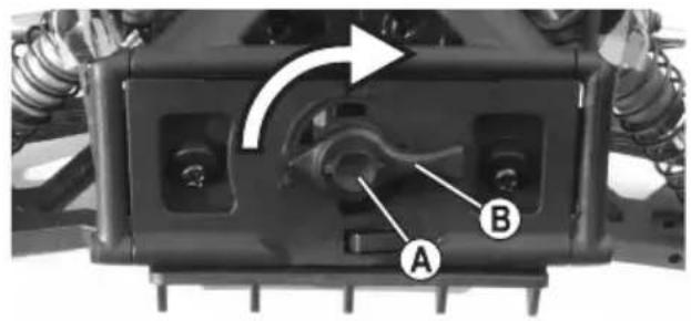
natural_image
Mechanical assembly component with labeled parts A and B, showing internal components and motion direction arrow (no text or symbols beyond labels)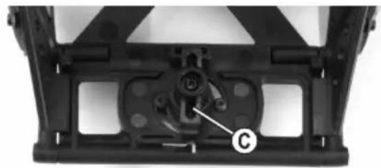
natural_image
Mechanical component with labeled part 'C' and mounting bracket (no readable text or symbols beyond label)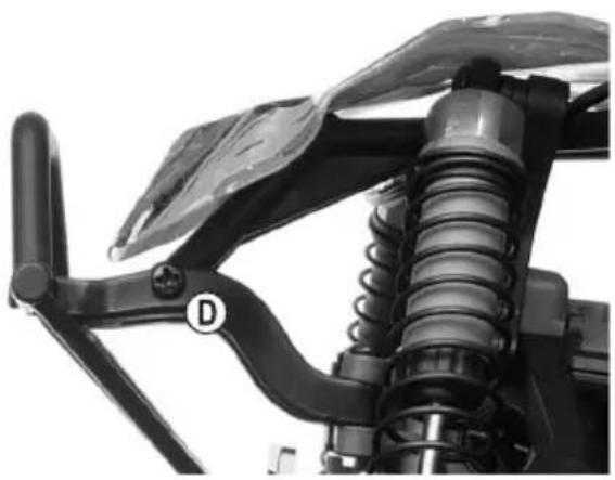
natural_image
Close-up of a mechanical suspension system with visible springs and a handle (no text or symbols)b) Inserting the drive battery in the vehicle

Important!
nicle accepts only one LiPo drive battery with 2 cells (rated voltage 7.4 V) or one NiMH drive battery with 6 to 7 cells (rated voltage 7.2 V or 8.4 V), which are not included.
The use of several drive batteries would cause overloading of the vehicle drive and thus its damage (e.g. differential). This will void the warranty/guarantee!
The drive battery type must match the speed controller/motor used. Make sure the undervoltage detection on your speed controller is enabled if you are using a LiPo drive battery.
Loosen the two hook-and-loop straps on the battery holder. Insert the drive battery into the battery holder. Pull the two hook-and-loop straps tight so that the drive battery is firmly held in place and fasten the hook-and-loop strap.
c) Setting the remote control and speed controller
The manufacturer's instructions and the relevant operating instructions must be strictly observed when setting the remote control and programming the speed controller.
The steering must be set so that the model moves straight ahead when the steering control on the transmitter is in the middle position. The steering angle to the right and left must be the same and the mechanical impact/blocking of wheels at full steering angle must be excluded.
The speed controller must be configured in such a way that the motor is switched off and the vehicle is immobilised when the drive function control on the transmitter is in the middle (neutral) position. In addition, the drive functions such as forward drive, stop with brake function and reverse drive must be reliably detected by the speed controller so that the motor is controlled accordingly.
Before testing the vehicle running performance, be sure to inspect the chassis and adjust, if necessary, as described in the following sections.
d) Configuring the camber
The camber is the inclination of the wheels as viewed from the front (vertical).
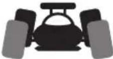
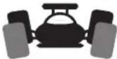
Negative camber Positive camber
(Upper wheel edge points inwards) (Upper wheel edge points outwards)
The alignment of the wheels is exaggerated in the two diagrams to show the difference between negative and positive camber. Obviously, such an extreme adjustment should not be made to the model vehicle!
- A negative camber on the front wheels increases the lateral forces on the tyres when turning corners. This makes the steering wheel more responsive and reduces the steering force. At the same time, the wheel is pushed onto the axle leg in the direction of the axis. This offsets axial bearing clearance and results in smoother driving.
- A negative camber on the rear wheels reduces the tendency of the rear of the vehicle to swing when turning corners.
- In contrast, a positive camber reduces the cornering force on the tyres and is generally not recommended.
Setting the front axle camber:
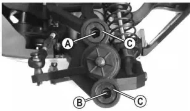
The "pivot ball" suspension on the front axle consists of a specially shaped steering knuckle, two spherical-head screws (A) and (B) and two outer plastic set screws (C).
You can learn this special form of wheel suspension during assembly.
To adjust the camber, the spherical-head screws (A) and (B) must be turned using a small 2.5 mm hex key (D), which is inserted through the hole of the set screw (C).
The plastic set screws (C) can be tightened or loosened with a larger 5 mm hex key (E). These are only intended for fixing the steering knuckle to the spherical-head screws (A) and (B).
Never use force to tighten the set screws (C), as this may prevent the wheel suspension from moving freely. However, the set screws (C) must not be too loose, otherwise the spherical-head screws and the steering knuckle may wobble.
text_image
A C B C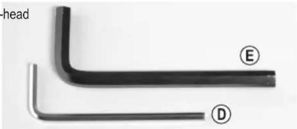
text_image
head E D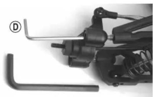
natural_image
Close-up of mechanical components including a spring and wrench, with no visible text or symbols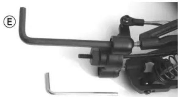
natural_image
Close-up of a mechanical assembly with tools and components (no visible text or symbols)Configuration options:
• To adjust the camber, use a small 2.5 mm hex key (D) to twist the metal ball screws.
- To tighten (or loosen) the plastic set screws, twist them with a larger 5 mm hex key (E). As described above, the metal spherical-head screws must be able to move slightly in the steering knuckle (however, they must not wobble).
Setting a negative camber:
Turn the upper spherical-head screw (A) in a clockwise direction to the right, and then turn the lower spherical-head screw (B) anticlockwise at the same angle.
Setting a positive camber:
Turn the upper spherical-head screw (A) in an anticlockwise direction to the left, and then turn the spherical-head screw (A) clockwise at the same angle.
Twist the spherical-head screws (A) and (B) over the small hex key (D) by a quarter turn only at a time and then check the changed driving behaviour.
The small hexagonal hole on the spherical-head screws (A) and (B) is only visible when you look directly through the large hexagonal hole on the plastic set screws (C).
Do not allow the spherical-head screws to protrude too much, otherwise the drive axle may fall off (or the thread on the screws may not hold in the suspension arms).
Setting the rear axle camber:
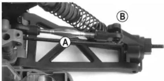
To adjust the camber, turn the screw (A) on the upper suspension arm.
This screw has a left and right-handed thread, therefore you do not need to remove the suspension arm to adjust the camber.
The rear steering knuckle (B) features several different holes to attach the upper suspension arm.
Attaching the suspension arm to a different hole changes the camber when the wheel moves up and down.
natural_image
Mechanical assembly diagram showing a spring-loaded component with labeled parts A and B (no text or symbols beyond labels)e) Configuring the wheel alignment
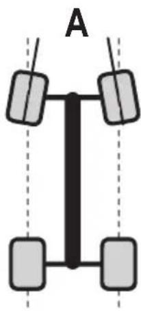
The wheel alignment (toe-in = figure A, toe-out = figure B) describes the alignment of the wheel plane relative to the direction of travel.
When the vehicle moves, the tyres are pushed apart due to rolling resistance. As a result, they are not parallel to the direction of travel.
To compensate for this, the tyres of the stationary vehicle can be adjusted in a way so that they point slightly inwards. This toe-in improves the lateral cornering of the tyre and therefore results in a more direct response to steering commands.
To decrease the steering response, use toe-out (the wheels of the stationary vehicle will point outwards).

A toe angle of more than 3^ toe-in (A) or toe-out (B) may cause steering difficulties and reduces the speed. It also increases tyre wear.
natural_image
Diagram of a vertical vehicle with four wheels and a central shaft, labeled 'A' (no text or symbols on the diagram itself)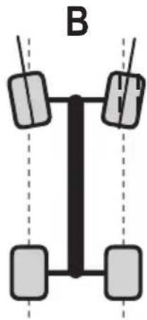
natural_image
Diagram of a vertical vehicle with four wheels and two side-mounted sensors, labeled 'B' (no text or symbols on the diagram itself)The figure above shows a heavily over-emphasised setting. It is only used to show the difference between toe-in and toe-out. If a similar setting is used for the vehicle, it will be very difficult to control!
Setting the front axle toe:
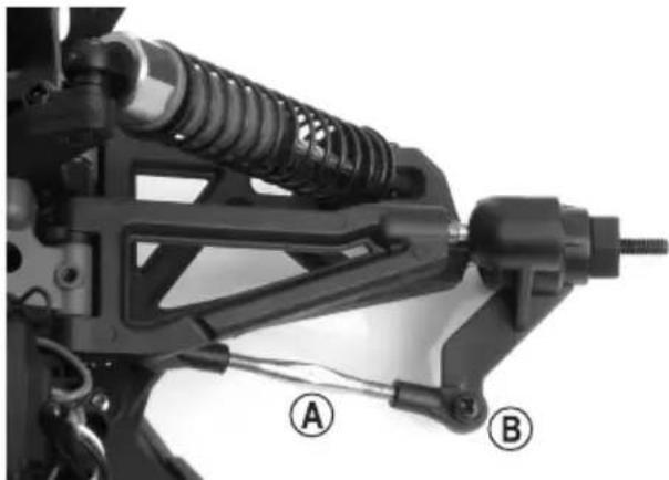
Turn the steering arm (A) to adjust the toe-in/toe-out for the front axle. The steering arm has a left and right-hand-ed thread, therefore you do not need to remove it when making adjustments.
Turn both steering knuckle arms the same amount (left and right front wheel). Otherwise, the trim on the transmitter has to be adjusted (or possibly the steering servo control by adjusting the servo rod).
There are several holes in the steering knuckle (B) to secure the steering arm; these are designed to change the steering lock angle for the front wheel (Ackermann angle).
natural_image
Mechanical assembly diagram showing a spring-loaded bracket with labeled parts A and B (no text or symbols beyond labels)Setting the rear axle toe:
The rear axle toe is preset and cannot be changed.
f) Adjusting the shock absorbers
natural_image
Mechanical assembly diagram showing suspension components labeled A, B, and C (no text or symbols beyond labels)Front axle
natural_image
Mechanical assembly diagram showing a spring-loaded frame with labeled components (A, B, C), no readable text or symbols beyond labels.Rear axle
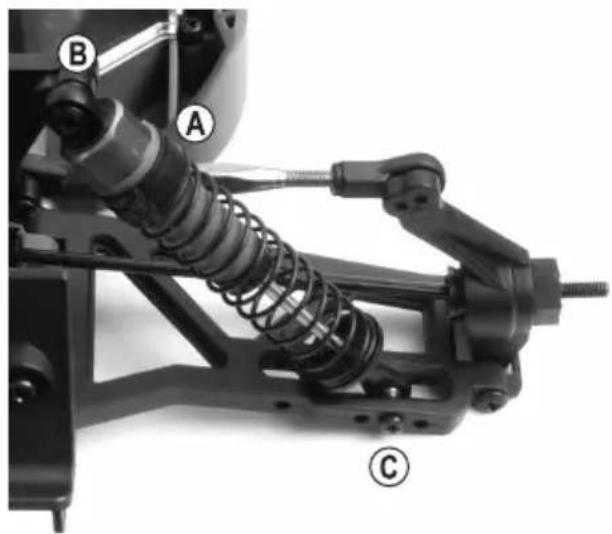
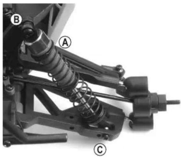
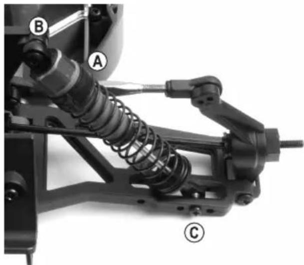
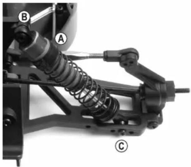
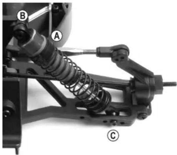
At the upper end of the shock absorber (A), the spring preload can be adjusted by inserting plastic clips.
The shock absorbers on the front and rear axle can be mounted in different positions above the shock absorber bridge (B) and on the bottom suspension arm (C).
Always ensure that the shock absorbers on each axle are level (i.e. on the left and right wheel of the front or rear axle), otherwise the vehicle may not respond correctly.
Professional drivers can also use springs with a different hardness grade or fill the shock absorbers with a shock absorber oil of a different viscosity. The installation of aluminium shock absorbers, which are adjustable by knurling, is possible.
As is the case with full-size vehicles, the shock absorbers (and the rubber seals in the shock absorbers) are wearable parts. If oil leaks from the shock absorbers (e.g. the suspension arm is coated in oil, or there is dripping oil), the gaskets or shock absorbers must be replaced.
10. Getting started
Follow exactly the procedure described below to ensure that the vehicle does not make uncontrolled movements during commissioning.
- Just like the drive rechargeable battery, the batteries or rechargeable batteries in the transmitter must be full or fully charged.
- Place the vehicle on a suitable surface so that the wheels can turn freely.
- Open the body, insert the fully charged drive battery into the battery compartment and secure it with the hook-and-loop straps.
- Switch on the remote control transmitter.
- Connect the drive rechargeable battery to the speed controller. If the speed controller has an additional on/off switch, turn it on. Do not reach into the drive and do not hold the vehicle by the wheels.
- Check the steering and drive functions as well as the neutral position of the drive (the motor must stop when you release the throttle lever on the transmitter).
- Close the body.
- For the first test drive, choose a suitable terrain so that the model does not hit an obstacle immediately in the event of a control error and thus become damaged.
- Start carefully until you get used to the driving behaviour of the vehicle.
- After the drive, first disconnect the drive rechargeable battery from the speed controller and then switch off the remote control.

Important!
witch off the transmitter when the drive rechargeable battery is connected to the model or the model is turned on.
11. Cleaning and care
a) General information
Before cleaning or maintenance, the speed controller must be turned off and the drive battery must be completely disconnected from the speed controller. Allow all parts to cool down completely (e.g. motor and speed controller).
After you have finished using the vehicle, remove all dust and dirt (e.g. using a clean long-haired brush and a vacuum cleaner). Compressed air sprays can also help to remove dirt.
Do not use cleaning sprays or conventional household cleaning chemicals. These may damage the electronic components and discolour the plastic parts or body.
Never wash the vehicle with water, e.g. with a high-pressure cleaner. This will destroy the motor, speed controller and receiver.
A soft, slightly dampened cloth can be used to wipe the body. Do not rub too hard, as this may result in scratch marks.
b) Before and after each use
Motor vibrations and impacts during vehicle operation may cause certain parts and screw fittings to become loose.
Before and after each use, check the following:
- All wheel nuts and screw fittings must be secure
- The speed controller, on/off switch, and receiver must be fixed
- Check the condition of the tyres and ensure that they adhere to the wheel rims
- Check that all cables are attached (they should not touch moving parts of the vehicle)
→ Check the vehicle for any signs of damage before and after each use. If there are any signs of damage, discontinue use immediately.
Only use original spare parts when replacing worn vehicle parts (e.g. tyres) or defective vehicle parts (e.g. a broken suspension arm).
c) Changing a tyre
The tyres are fixed on the wheel rim and cannot be removed. Therefore, if a tyre is worn, the entire wheel must be replaced.
After loosening the wheel nut (A), pull the wheel off the wheel axle.
Attach the new wheel so that the hex socket on the inside of the wheel rim fits exactly over the wheel hub nut.
Screw the wheel tight to the wheel axle with the wheel nut (A) removed at the beginning. Do not apply any force when tightening the wheel nut, otherwise the wheel will not spin freely and the drive may be damaged.
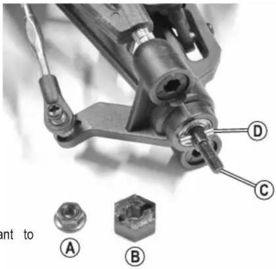
It may be that the wheel hub nut (B) remains in the rim when the rear wheel is removed or it comes off the wheel axle (C). Ensure that the drive pin (D) does not fall off.
If the wheel is subsequently re-fitted, it is important to check that the drive pin (D) is inserted exactly into the centre of the wheel axle (C) and that it is positioned in the corresponding notch on the wheel hub nut (B).
If the drive pin (D) is missing, no torque can be transferred from the engine to the wheel and the wheel will spin freely.
text_image
D C A B ant to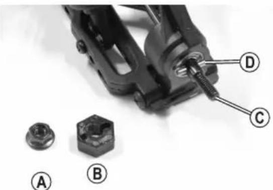
text_image
Technical diagram showing mechanical assembly with labeled parts A, B, C, and D, including a threaded component.d) Adjusting the backlash
Ensure the backlash is adjusted correctly after the vehicle has been assembled and before using it for the first time. It is also recommended that you check the backlash regularly.
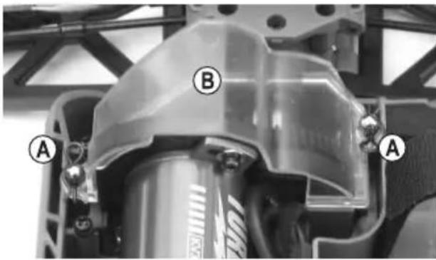
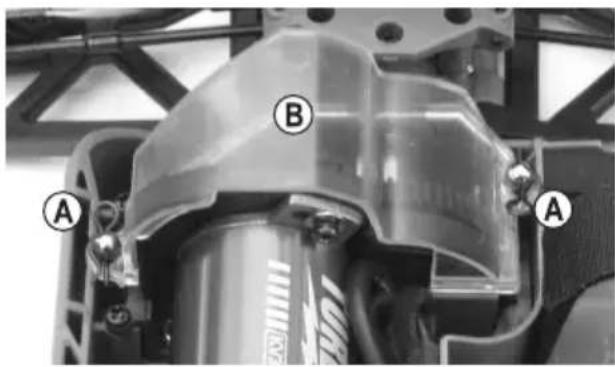
Pull out the two clips (A), then remove the dust cover (B).
Basically, the distance between the main gear (C) and the engine pinion (D) must be as small as possible, but without the gears running strictly.
Loosen the upper fixing screw (E) of the engine a little bit. Gently slide the engine with the engine pinion (D) in the direction of the main gear (C).

The engine must not shake; the fixing should only be loosened enough to allow the engine to move.
The engine pinion and the main gear will now be engaged without backlash. However, this is not optimal for the service life of the gears!
Place a strip of thin paper (F) between the main gear (C) and the engine pinion (D). Turn the main gear so that the paper strip (max. 80 g!) is pulled between the two gears.
The pressure of the paper pushes the electric engine by the required amount.
Tighten the fixing screw (E) on the engine.
When you turn the main gear in the other direction to remove the strip of paper (G), both gears should be at the correct distance to one another.

Ideally, the engine pinion should be as close as possible to the main gear whilst ensuring that the cogs do not touch, as this makes the gears too tight.
text_image
A B A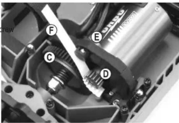
text_image
F E C D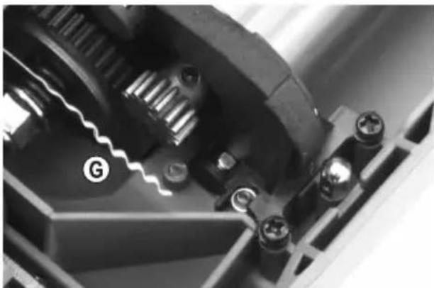
natural_image
Close-up of mechanical gear and housing components (no visible text or symbols)If the gears (engine pinion and main gear) are too far apart, the cogs on the main gear will be damaged by the engine pinion after just a few seconds, which will void the warranty/guarantee!
However, if the engine pinion presses against the main gear (i.e. there is no clearance between the cogs), this will decrease performance, increase power consumption (the engine requires lots of power to turn the main gear) and lead to premature wear.
e) Adjusting the friction clutch
The friction clutch protects the gears against overload (e.g. on non-slip surfaces).
In addition, adjusting the friction clutch correctly prevents the vehicle from overturning due to the brushless engine's high torque.

The manufacturer has configured the optimal setting, therefore you do not normally need to make any changes.
However, very frequent start-ups with full power on a surface with good grip can cause the slip clutch linings to wear off over time, whereby an adjustment of the slip clutch may possibly be required. Furthermore, professional operators can adjust the friction clutch based on the preferred starting behaviour on a specific surface.
To adjust the clutch, proceed as follows:
Pull out the two clips (A), then remove the dust cover (B).
The friction clutch can be adjusted by turning the hex nut (C).
Turn the hex nut clockwise (when viewed from the rear of the vehicle) to increase the drive power to the gearbox, or anticlockwise to decrease the power transmission.

If the friction clutch is too tight, the maximum drive power will be transmitted and the clutch will not function.
This may damage the differential and the vehicle may overturn on non-slip surfaces due to the high torque from the brushless engine.
If the friction clutch is too "soft", this places significant wear on the friction clutch. It affects acceleration and may prevent the vehicle from moving (due to spinning of the friction clutch).

Adjust the clutch in very small steps (max. 1/4 turn) and check how the vehicle responds. Make a note of each change so that you can revert to the previous setting if necessary.
text_image
A B A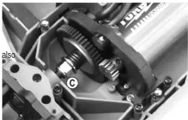
natural_image
Close-up mechanical assembly showing gears and housing components (no visible text or symbols)12. Disposal
a) Product

Electronic devices are recyclable waste and must not be placed in household waste. At the end of its service life, dispose of the product according to the relevant statutory regulations.
Remove any inserted batteries and dispose of them separately from the product.
b) (Rechargeable) batteries
You as the end user are required by law (Battery Ordinance) to return all used batteries/rechargeable batteries. Disposing of them in the household waste is prohibited.

Contaminated (rechargeable) batteries are labelled with this symbol to indicate that disposal in the domestic waste is forbidden. The abbreviations for heavy metals in batteries are: Cd = Cadmium, Hg = Mercury, Pb = Lead (name on (rechargeable) batteries, e.g. below the trash icon on the left).
Used batteries can be returned to local collection points, our stores or battery retailers.
You thus fulfil your statutory obligations and contribute to environmental protection.
13. Troubleshooting
This model was built using the latest technology. However, faults and malfunction may still occur. The following section shows you how to troubleshoot potential problems. Ensure that you also read the remote control operating instructions included with the product.
The model does not respond or responds incorrectly
- In the case of 2.4 GHz remote controls, the receiver must be connected to the transmitter. This process is known as “binding” or “pairing”. Please also note the operating instructions for the remote control.
- Is the vehicle drive battery or the transmitter batteries/rechargeable batteries empty? Replace the drive battery or batteries/rechargeable batteries in the transmitter with new ones.
- Did you switch on the transmitter before switching on the speed controller?
- Is the drive battery connected to the speed controller correctly? Check the connection to see if it is dirty or oxidised.
- Is the vehicle too far away? With a fully charged drive battery and batteries/rechargeable batteries in the transmitter, a minimum range of 50 m should be possible. However, it can be reduced by outside influences, such as interference on the radio frequency or the proximity of other transmitters (not only remote control transmitters, but also Wi-Fi/Bluetooth® devices that also use a transmission frequency of 2.4 GHz), metal parts, buildings, etc.
The position of the transmitter and receiver antennas relative to each other also has a significant impact on the range. For best results, the transmitter and receiver antennas should be vertical (i.e. parallel to each other). Pointing the transmitter antenna at the vehicle significantly reduces the range.
- Check the correct position of the speed controller plug and steering servo on the receiver. If the plugs have been rotated 180^ , the speed controller and steering servo will not work.
If the connectors for the speed controller and steering servo are swapped, the throttle/brake lever will control the steering servo and the rotary control will control the drive function!
The vehicle doesn't stop when the throttle/brake lever is released
- Correct the throttle trim on the transmitter (set the neutral position).
- Reprogramme the neutral position on the speed controller (and the full throttle position for forward and reverse drive) if your speed controller has this function.
The vehicle travels slowly or the steering servo does not respond properly to remote control commands; the range between the transmitter and the vehicle is very short
• The drive battery is nearly empty.
Modern electronic speed controllers have a built-in BEC that ensures power supply of the receiver and steering servo. As a result, the receiver will not function properly when the drive battery is nearly empty. Replace the drive battery with a fully charged drive battery (before changing the battery, wait for at least 5–10 minutes for the motor and speed controller to cool down).
- Check the batteries/rechargeable batteries in the transmitter.
The vehicle slows down or comes to a standstill while being driven
- The drive battery is weak or empty, or the motor was switched off by the undervoltage detection function of the speed controller.
- The speed controller is too hot and it switched the motor off. Wait a few minutes until the speed controller has cooled down. If your speed controller has a cooling fan, check its functionality.
- The speed controller (or receiver) you are using has a failsafe function and no valid control signal was recognised; as a result, the motor was disabled by the speed controller or receiver for safety reasons.
The vehicle does not travel in a straight line
- Set the steering trim on the transmitter.
- Check the steering linkage, servo arm, servo saver and screw connection.
- Did the vehicle have an accident? If so, check the vehicle for any defective or broken parts and replace them if necessary.
The vehicle moves in the opposite direction to the rotary control on the transmitter
- Use your transmitter to activate the reverse setting for the steering function.
The vehicle responds in the opposite way to the throttle/brake lever on the transmitter.
- If you are using a pistol grip transmitter, the vehicle must typically move forward when the throttle/brake lever is pulled towards the handle. Otherwise, use your transmitter to activate the reverse setting for the drive function.
- If a brushless motor is used, swap two of the three motor cables against each other. This will reverse the rotational direction of the motor.
The vehicle does not steer properly or the steering angle is too low
- Your transmitter may have a dual rate setting or an upper limit of the servo travel. Follow the operating instructions for your transmitter.
- Check the steering mechanism for loose parts (e.g. check whether the servo arm is attached correctly to the servo).
- When installing the servo in the vehicle, make sure that the servo is in the middle position before mounting the servo arm.
The LED light bar does not glow or glows weakly
- The LED light bar is plugged into a free socket on the receiver. Check the polarity of the plug.
14. Specifications
Scale....1:10
Suitable drive battery types ....LiPo drive battery with 2 cells (rated voltage 7.4 V) or NiMH drive battery with 6 to 7 cells (rated voltage 7.2 V or 8.4 V) depending on the speed controller used
Recommended motor......Brushed electric motor, type 550, 13 turns or brushless electric motor, type 3652, 3000 KV
Recommended speed controller......Brushed or brushless speed controller (depending on the motor), continuous current min. 40 A
Recommended steering servo....Standard size, min. 4 kg/40 Ncm
Recommended remote control ......Pistol grip remote control 2.4 GHz, 2 channels
Drive All-wheel drive via cardan shaft
Front and rear axle differential
Chassis....Independent suspension, double wishbones
Oil-filled shock absorbers with coil springs, adjustable
Adjustable front wheel toe
Adjustable front and rear wheel camber
Dimensions (L x W x H)....420 x 295 x 165 mm
Tire dimensions (W x ∅)....49 x 105 mm
Wheel base....275 mm
Ground clearance....58 mm
Weight ....Depending on motor/speed controller/rechargeable battery, ready-to-use, approx. 2.3 – 2.5 kg
Page
France (email) : technique@conrad-france.fr
text_image
Technical diagram of a vehicle chassis component with labeled parts A and B, showing structural details and an arrow indicating rotation or movement.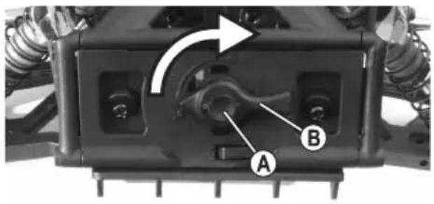
text_image
Technical diagram of a vehicle chassis component with labeled parts A and B, showing internal components and directional arrow.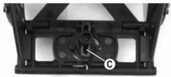
natural_image
Mechanical component with labeled part C, no visible text or symbols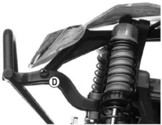
natural_image
Close-up of a mechanical assembly with springs and a handle, no visible text or symbolsnatural_image
Two black L-shaped metal bars labeled D and E, shown side by side on a plain background (no text or symbols beyond labels)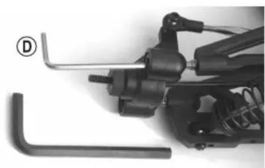
natural_image
Close-up of mechanical components including a wrench and spring assembly (no visible text or symbols)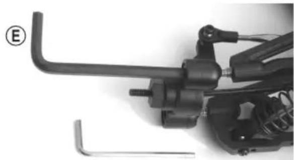
natural_image
Close-up of a mechanical assembly with tools and components (no visible text or symbols)natural_image
Mechanical assembly diagram showing a spring-loaded component with labeled parts A and B (no text or symbols beyond labels)natural_image
Simple diagram of a vertical structure with four rectangular blocks and two horizontal lines, labeled 'A' at the top (no text or symbols within the diagram itself)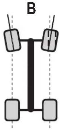
natural_image
Pure diagram of a vertical structure with four rectangular blocks and dashed vertical lines, no text or symbols present.
natural_image
Mechanical assembly diagram showing spring and connecting components labeled A and B (no text or symbols beyond labels)natural_image
Mechanical assembly diagram showing suspension system components labeled A, B, and C (no text or symbols beyond labels)Essieu avant
natural_image
Mechanical assembly diagram showing a car suspension system with labeled components (A, B, C), no text or symbols present.Essieu arrière
text_image
Technical diagram of a mechanical assembly with labeled parts A, B, C, and D, showing bolted connection details.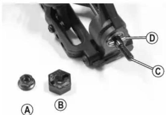
natural_image
Mechanical assembly with labeled parts (A, B, C, D) showing a bolt and nut assembly (no text or symbols beyond labels)text_image
Technical diagram of a mechanical assembly with labeled parts C, D, E, and F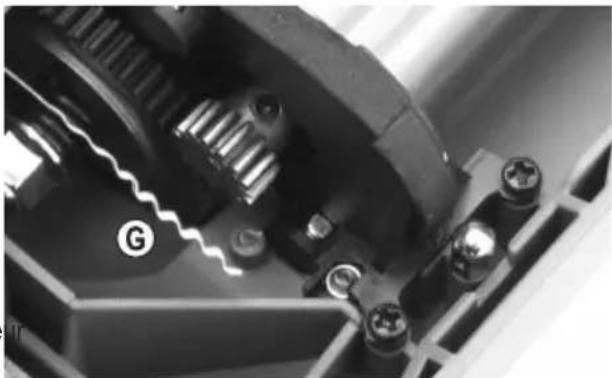
natural_image
Close-up mechanical assembly showing gear and housing components (no visible text or symbols)text_image
Technical diagram of a mechanical assembly with labeled parts A and B, showing internal components and mounting hardware.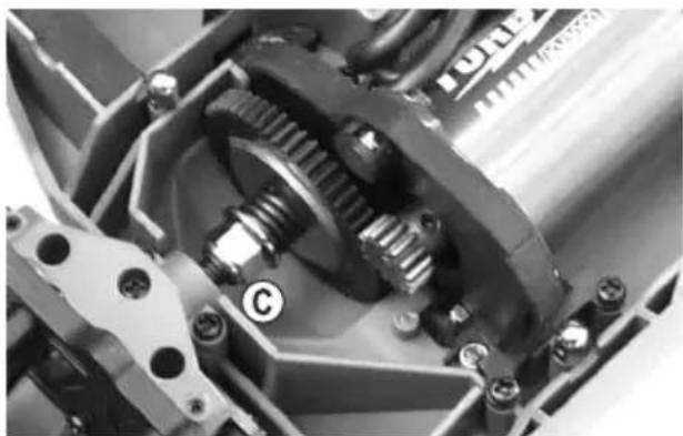
natural_image
Close-up mechanical assembly showing gears and shafts in a mechanical assembly (no visible text or symbols)text_image
Technical diagram of a vehicle chassis with labeled components A and B, showing internal components and a directional arrow indicating rotation.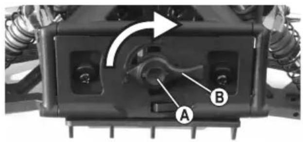
text_image
Technical diagram of a vehicle chassis with labeled components A and B, showing mechanical assembly and directional arrow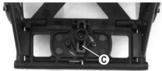
natural_image
Mechanical component with labeled part 'C' and mounting bracket (no readable text or symbols beyond label)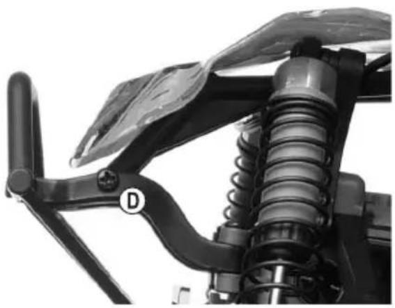
natural_image
Close-up of a mechanical suspension system with visible springs and a handle (no text or symbols)natural_image
Two black L-shaped metal bars labeled D and E, shown against a plain background (no text or symbols beyond labels)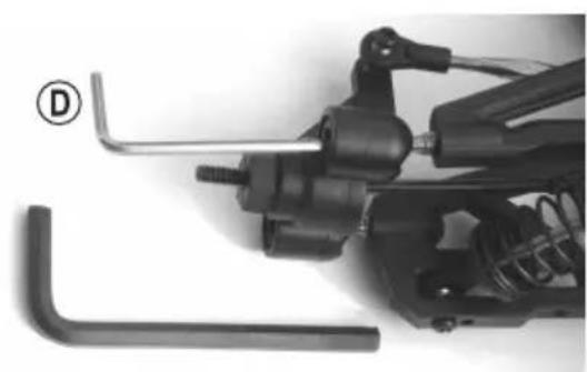
natural_image
Close-up of mechanical components including a wrench and spring, with no visible text or symbols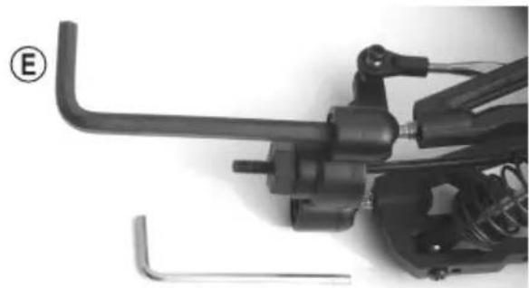
natural_image
Close-up of a mechanical assembly with levers and springs (no visible text or symbols)(Instelopties:
natural_image
Mechanical assembly diagram showing a spring-loaded component with labeled parts A and B (no text or symbols beyond labels)e) Spoor instellen
natural_image
Simple diagram of a vertical structure with four wheels and two top-mounted blocks, labeled 'A' at the top (no text or symbols on the diagram itself)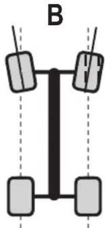
natural_image
Diagram of a vertical vehicle with four wheels and two side-mounted sensors, labeled 'B' (no text or symbols on the diagram itself)
natural_image
Mechanical assembly diagram showing a spring-loaded frame with labeled components (A and B), no readable text or symbols beyond labels.natural_image
Mechanical assembly diagram showing suspension system components labeled A, B, and C (no text or symbols beyond labels)Vooras
natural_image
Mechanical assembly diagram showing a spring and suspension components labeled A, B, and C (no text or symbols beyond labels)Achteras
text_image
Technical diagram of a mechanical assembly with labeled parts A, B, C, and D, showing bolted connection details.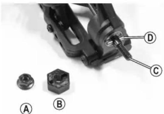
natural_image
Mechanical assembly with labeled parts (A, B, C, D) showing a bolt and nut assembly (no text or symbols beyond labels)text_image
Technical diagram of a mechanical assembly with labeled parts A and B, showing internal components and mounting hardware.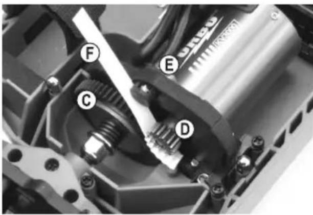
text_image
Technical diagram of a mechanical assembly with labeled parts C, D, E, and F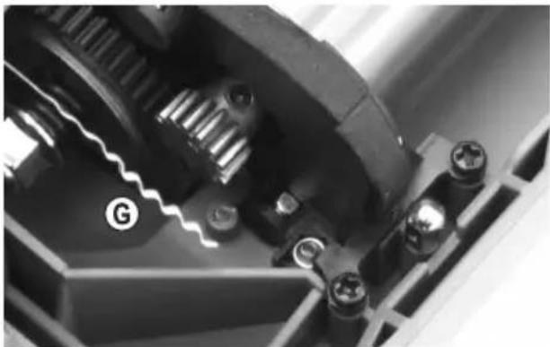
natural_image
Close-up of a mechanical gear assembly with visible teeth and mounting holes (no text or symbols)
natural_image
Close-up of a mechanical gear assembly with visible gears and housing (no text or symbols)GB This is a publication by Conrad Electronic SE, Klaus-Conrad-Str. 1, D-92240 Hirschau (www.conrad.com).
All rights including translation reserved. Reproduction by any method, e.g. photocopy, microfilming, or the capture in electronic data processing systems require the prior written approval by the editor. Reprinting, also in part, is prohibited. This publication represents the technical status at the time of printing.
Copyright 2021 by Conrad Electronic SE.
Copyright 2021 by Conrad Electronic SE.
Copyright 2021 by Conrad Electronic SE.