Carbon Fighter III - Remote control toy Reely - Free user manual and instructions
Find the device manual for free Carbon Fighter III Reely in PDF.


User questions about Carbon Fighter III Reely
0 question about this device. Answer the ones you know or ask your own.
Ask a new question about this device
Download the instructions for your Remote control toy in PDF format for free! Find your manual Carbon Fighter III - Reely and take your electronic device back in hand. On this page are published all the documents necessary for the use of your device. Carbon Fighter III by Reely.
USER MANUAL Carbon Fighter III Reely
GB Operating Instructions Page 33 - 63
www.business.conrad.at

Tel.: 0848/80 12 88
Fax: 0848/80 12 89
E-Mail: support@conrad.ch
natural_image
Top-down view of a toy car chassis showing front wheel, suspension components, and engine assembly (no visible text or symbols)Bild 1
natural_image
Mechanical assembly diagram showing a motor and gear assembly with no visible text or symbolsBild 2
text_image
Technical diagram of a mechanical assembly with labeled parts including CT and numbered componentsBild 4

Achtung!
natural_image
Close-up of a vehicle tire assembly with attached suspension components (no visible text or symbols)Bild 9
natural_image
Close-up of a vehicle chassis with visible tire, suspension, and mounting bracket (no text or symbols)Bild 10
natural_image
Diagram of a vertical structure with four rectangular blocks connected by a central black bar, no text or symbols present.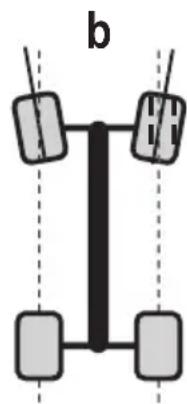
natural_image
Simple diagram of a vertical structure with four rectangular blocks connected by lines, no text or symbols present.Bild 11

natural_image
Close-up of a vehicle chassis with tire and suspension components, no visible text or symbols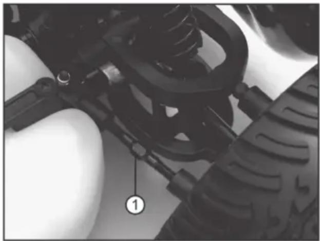
natural_image
Close-up of a mechanical assembly with visible springs and components, no text or symbols presenttext_image
Labeled diagram of a vehicle chassis showing tire, suspension components, and numbered parts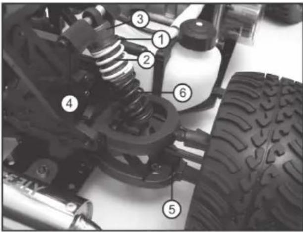
text_image
Labeled mechanical assembly diagram showing components like springs, tires, and a vehicle chassistext_image
Technical diagram of a mechanical assembly with numbered components labeled 1, 2, and 3.Bild 17

text_image
Technical diagram of a mechanical assembly with numbered components, likely a motor or engine component.Bild 19
12. Entsorgung
a) Allgemein
- Introduction ...... 34
- Intended Use 35
- Explanation of Symbols 35
- Scope of Delivery 36
- Safety Information 36
a) General Information 37
b) Commissioning 38
c) Driving the Vehicle 39
-
Notes on Batteries and Rechargeable Batteries 40
-
Charging the batteries 41
a) Charging Receiver Battery 41
b) Charging Rechargeable Batteries in the Transmitter 41
- Commissioning 42
a) Removing the Car Body 42
b) Installing the Receiver Aerial Cable 42
c) Inserting Receiver Battery into the Vehicle 43
d) Taking the Transmitter and Receiver System into Operation 43
e) Programme Fail-Safe 43
f) Oil Air Filter and Fuel Vehicle 44
g) Attaching and Fastening the Car Body and Rear Wing 44
h) Checking the Range of the Remote Control 44
i) Starting the Engine 45
j) Controlling the Vehicle 46
k) Stopping the Vehicle 47
- Vehicle Settings 48
a) Setting the Camber 48
b) Setting the Alignment 50
c) Setting the Steering Geometry 51
d) Setting the Shock Absorbers 52
e) Setting the Servo Saver 53
- Motor Settings 54
a) General Setting of the Carburettor 54
b) Setting the Idle Mixture Adjustment Screw (L) 55
c) Setting the Main Nozzle Needle (H) 55
d) Setting the Idling Mixture Speed (S) 56
e) Recovering the Factory Settings 56
-
Cleaning and Maintenance 57
-
Disposal 59
a) General Information 59
b) Batteries and Rechargeable Batteries 59
- Declaration of Conformity (DOC) 59
- Troubleshooting 60
- Technical Data 63
1. Introduction
Dear Customer,
Thank you for purchasing this product.
This product complies with the statutory national and European requirements.
To maintain this status and to ensure safe operation, you as the user must observe these operating instructions!

These operating instructions are part of this product. They contain important notes on commissioning and handling. Also consider this if you pass on the product to any third party.
Therefore, retain these operating instructions for reference!
All company names and product names are trademarks of their respective owners. All rights reserved.
If there are any technical questions, contact:

Tel. no.: +49 9604 / 40 88 80
Fax. no.: +49 9604 / 40 88 48
E-mail: tkb@conrad.de
Mon. to Thur. 8.00am to 4.30pm, Fri. 8.00am to 2.00pm
2. Intended Use
The product is a model car with rear-wheel drive which can be radio-controlled with the enclosed wireless remote control.
The chassis is constructed ready to drive.
This product is not a toy and not suitable for children under 14 years of age.

Observe all safety information in these operating instructions. They contain important information on handling of the product.
3. Explanation of Symbols

The symbol with the exclamation mark points out particular dangers associated with handling, function or operation.

The „arrow“ symbol indicates special advice and operating information.
4. Scope of Delivery
- Ready-to-run vehicle, RtR
- Transmitter
- Small parts (e.g. aerial tubes for receiver aerial)
- Spark plug wrench
- Operating instructions for the vehicle
- Operating instructions for the remote control system
Required Accessories (not part of the delivery):
- 4 rechargeable or normal batteries (type mignon AA) for the transmitter
- Receiver battery (Hump pack 6 V, 1500 mAh recommended)
- Charger for transmitter and receiver battery
- Tank bottle
• Air filter oil - Two-stroke mixture 1:25 oil/fuel mixture (with Super or Super Plus fuel)

The spare part list can be found on our website www.conrad.com in the download section for the respective product.
Alternatively, you may also call to request the list of spare parts. For contact information, see the chapter "Introduction" at the beginning of these operating instructions.
5. Safety Information

In case of damage caused by non-compliance with these operating instructions, the warranty/guarantee will expire. We do not assume any liability for consequential damage!
We do not assume any liability for damage to property or personal injury caused by improper use or the failure to observe the safety instructions! In such cases the warranty/guarantee will expire.
Normal wear and tear during operation (e.g. worn tyres, worn gears) and damage from accidents (e.g. broken transverse links, twisted chassis, etc.) are excluded from the guarantee and warranty.
Dear customer, these safety instructions are not only for the protection of the product but also for your own safety and that of other people. Therefore, read this chapter very carefully before taking the product into operation!
a) General Information

Caution, important note!
Operating the model may cause damage to property and/or individuals. Therefore, make sure that you are sufficiently insured when using the model, e.g. by taking out private liability insurance. If you already have private liability insurance, verify whether or not operation of the model is covered by your insurance before commissioning your model.
- For safety and licensing (CE) reasons, unauthorised conversion and/or modifications to the product are not permitted.
- This product is not a toy and not suitable for children under 14 years of age.
- The product must not become damp or wet.
- Never touch the motor and exhaust during operation! Danger of burns and injury!
- Keep the fuel locked away, store it inaccessible for children.
- Avoid contact with eyes, mucous membranes and skin. Consult a doctor immediately if you feel unwell!
- Never spill the fuel. Use a special fuel bottle to fuel the car.
- Test-runs or drives must only take place outdoors. Do not inhale the fuel and exhaust fumes; they are hazardous to health!
- The fuel is highly combustible; the fuel vapours are highly explosive! Never smoke when handling fuels (e.g. when fuelling up). Keep away naked flame! Danger of explosion and fire!
- Fuel must be kept in well-ventilated rooms only, away from ignition sources and in approved quantities only.
- If driving operation is permanently terminated, the fuel remaining in the model tank must be pumped out.
- Do not leave the packaging material lying around carelessly as it can become a dangerous toy for children.
- Should questions arise that are not answered by the operating manual, contact us (for contact information, see chapter 1) or another expert.

The operation and handling of remote controlled model cars must be learned! If you have never driven such a vehicle before, drive particularly carefully and get used to the reactions of the car to the remote control commands first. Do be patient!
Do not take any risks when operating the product! Your own safety and that of your environment depends completely on your responsible use of the model.
- The intended operation of the vehicle requires maintenance work or repairs from time to time. The tyres, for example, will wear during operation, and there may be „accident damage“ due to driving errors.
Only use genuine spare parts for the maintenance and repair work you then have to perform!
b) Commissioning

The manual for the remote control system is included separately. Always observe all safety information included in it as well as any other information!
Always commission the vehicle according to the following sequence. Otherwise, unpredictable reactions of the vehicle may result! Also observe chapter 8.
Step 1:
Switch on the transmitter if you haven't done so already. Check its function (e.g. operation display of the transmitter).
Step 2:
Place the vehicle on an appropriate surface so that the wheels can move freely.
Connect the receiver power supply and put the on/off switch for the receiver power supply in the „ON“ position (= switched on).
Step 3:
Before operating the vehicle, check whether the stationary model reacts as expected to the commands of the remote control (throttle and steering servo).
Step 4:
Set the trimming for throttle/brake at the transmitter so that the brake will not catch when the lever (neutral position of the throttle/brake lever at the transmitter) is released entirely.
Step 5:
Set the trim for steering so that the front wheels are about straight. The exact setting for straight driving can be performed during a drive.
Step 6:
Check the throttle and steering servo for whether they run „to block“ in operation mechanically at the corresponding full deflection at the transmitter. In this case, the servo path at the transmitter must be adjusted accordingly (see operating instructions of the remote control).
Step 7:
Programme a failsafe function on the throttle servo (if integrated in the remote control) and check it for correct function. If this function is not integrated into the remote control, we urgently recommend using a failsafe module (must be purchased separately.
c) Driving the Vehicle
- Improper operation may cause serious injury and property damage! Only drive with the model directly in view. This is why you shouldn't drive at night.
- Only drive when your ability to react is unrestricted. Exhaustion or the influence of alcohol or medication can cause incorrect responses, just as with real vehicles.
- Please note that this model vehicle must not be driven on public roads, places or streets. Also do not operate it on private grounds without the owner's permission.
- Don't drive towards animals or people!
- Do not drive in rain, through wet grass, water, mud or snow. The model is not waterproof or watertight.
- Avoid driving at very low outdoor temperatures. In the cold, the plastic of the car body and the chassis parts can lose its elasticity; in this case, small accidents can already lead to damage to the model.
- Do not drive in the case of a thunderstorm, under high-voltage power lines or in the proximity of radio masts.
- Never touch the ignition cable or spark plug connector when the motor runs. High voltage, danger to life!
- Gear transmission is designed for off-road use. In case of permanent driving on roads, the engine may overrev.
- Leave the transmitter on while the vehicle is in operation. Always switch off the motor first to park the vehicle. Then switch off the receiver power supply (switch to „OFF“). Now you may turn off the transmitter.
- The range of the transmitter decreases when the batteries (or rechargeable batteries) are weak. Weak batteries (or rechargeable batteries) in the receiver system prevent powerful operation of the sensor. Before going on a drive, check the charge condition of the batteries or rechargeable batteries in the transmitter and receiver.
Due to its size, the vehicle is equipped with a very strong steering servo. It has an increased power demand. For this reason, a high-performance receiver current supply is required (e.g. 5-cell Hump battery pack).
Check the receiver power supply before and after each drive. If the voltage is too low, the servos will only show weak reactions, so that the vehicle will no longer react to the control commands from the transmitter. The receiver may also show unpredictable responses.
Terminate driving operation at once (switch off motor, switch off receiver power supply, switch off transmitter) if the reaction of the receiver system is not as desired. Then replace the receiver power supply or recharge it.
- The motor and drive parts (e.g. exhaust, clutch) heat in operation. Wait at least 5 to 10 minutes before each new drive.

Do not touch the motor and drive parts (exhaust, etc.) until they have cooled down. Danger of burns!
6. Notes on Batteries and Rechargeable Batteries
- Keep batteries/rechargeable batteries out of the reach of children.
- Do not leave any batteries/rechargeable batteries lying around openly. There is a risk of batteries being swallowed by children or pets. In this case, see a doctor immediately!
- Batteries/rechargeable batteries must never be short-circuited, disassembled or thrown into fire. There is a danger of explosion!
- Leaking or damaged batteries/rechargeable batteries can cause chemical burns to skin. Wear suitable protective gloves when handling them.
- Never recharge normal (non-rechargeable) batteries. There is a risk of fire and explosion! Only charge rechargeable batteries intended for this purpose. Use suitable battery chargers.
- Always observe correct polarity (positive/+ and negative/-) when inserting the batteries/rechargeable batteries.
- To avoid damage during damage from leaking batteries/rechargeable batteries, remove the batteries (or rechargeable batteries) from the transmitter when the device is not used over an extended period of time (e.g. when stored). Disconnect the receiver battery from the receiver completely.
Recharge the rechargeable batteries about every 3 months. Otherwise, so-called deep discharge may result, rendering the rechargeable batteries useless. - Always replace the entire set of batteries or rechargeable batteries in the transmitter. Never mix fully charged batteries/rechargeable batteries with partially discharged ones. Always use batteries or rechargeable batteries of the same type and manufacturer.
- Never mix batteries and rechargeable batteries! Use batteries or rechargeable batteries for the transmitter.
- When using LiPo batteries in the vehicle, always observe the manufacturer's information on handling or charging LiPo batteries.
The transmitter can be operated with rechargeable instead of regular batteries.

However, the low voltage (batteries = 1.5 V, rechargeable batteries = 1.2 V) and the lower capacity of rechargeable batteries does lead to a decrease of the operating time. Usually this does not matter, as the operating time of the transmitter by far exceeds the operating time of the receiver batteries in the vehicle.
When using batteries in the transmitter, we recommend the use of high-quality alkaline batteries.
7. Charging the Batteries
a) Charging the Receiver Battery
- For operation of the vehicle, a separate, high-performance receiver current supply is required because the power demand is very high, particularly for the steering servo.

We recommend using a high-current-capable 5-cell NiMH hump battery pack as receiver power supply.
- Disconnect the receiver battery from the receiver before charging and remove it from the vehicle's battery box.
- Observe the operating instructions for the charger used when charging the receiver batteries.
- Rechargeable batteries heat up when charged or discharged (driving the vehicle). Wait until the rechargeable batteries have reached room temperature before charging them. The same applies after the charging procedure. Do not use the rechargeable battery in the vehicle until it has cooled down completely after the charge process.
b) Charging Rechargeable Batteries in the Transmitter
Also observe the separately enclosed operating instructions for the transmitter.
8. Commissioning
a) Remove Car Body
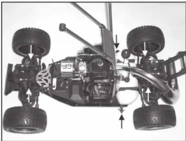
Remove the four holding clips of the over-roll bar (2 x above the front axle; 2x left/right of the tank) and the two clips at the sides of the rear wheels (see arrows in figure 1).
Pull the over-roll bars from the side of the holders and put them vertically. Lift and twist the car body so that it can be removed from the folded-up over-roll bar.
natural_image
Top-down view of a toy car showing front wheel, suspension, and engine components (no visible text or symbols)Figure 1
b) Installing the Receiver Aerial Cable
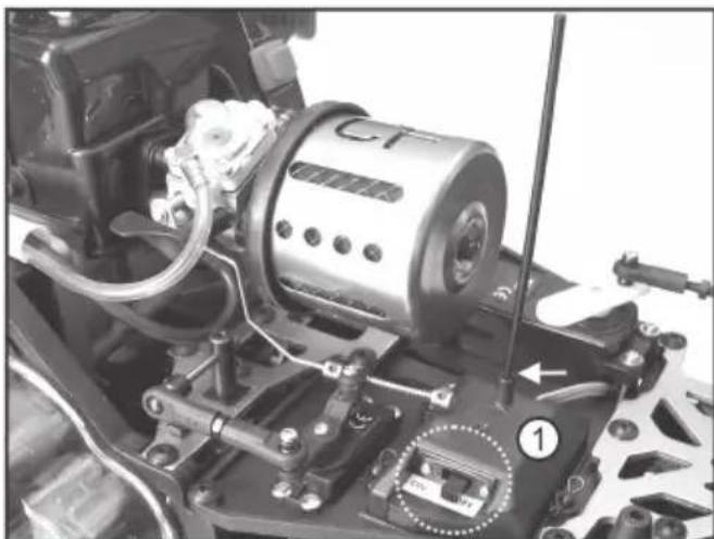
First put the on/off switch for the receiver (see circle in figure 2) in the „OFF“ position (off).
Open the receiver box (figure 2, item 1) by pulling off the three clips.
Guide the aerial cable through the receiver box lid and the aerial tube (see included accessories).
Route the battery connection cable of the on/off switch out of the receiver box (also see figure 3, item 4).
After closing the receiver box, push the tube into the holder at the top of the receiver box (see arrow in figure 2).
Simply let excess cable protrude loosely from the tip of the aerial tube.
natural_image
Close-up mechanical assembly of a vehicle's engine and motors, showing no visible text or symbolsFigure 2
For best range, the aerial cable must protrude from the vehicle vertically.

Never shorten the aerial cable! Never coil the aerial cable! This greatly reduces the range.
c) Inserting Receiver Battery into the Vehicle
Due to the high current demand of the two servos, high-performance a receiver battery is required (as with a combustion-engine model vehicle) (we recommend a 5-cell NiMH hump battery pack).
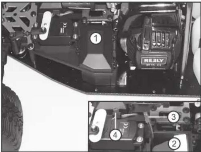
Open the battery box (figure 3, item 1) by pulling off the three clips and insert the receiver battery (figure 3, item 2).
Route the connection cable of the battery out of the battery box (figure 3, item 3) and connect it to the red two-pin BEC plug that was routed out of the receiver box from the on/off switch (figure 3, item 4).
Close the battery box again; make sure that no cables are bent or squeezed.
text_image
① RE3LY 2016.27 ② ③ ④ ①Figure 3
d) Taking the Transmitter and Receiver System into Operation
Open the battery compartment on the transmitter and insert new batteries or fully charged rechargeable batteries. Observe correct polarity (plus/+ and minus/-), see label on the battery compartment. Close the battery compartment again.
Switch on the transmitter. Check the functions at the transmitter.

Observe the enclosed operating instructions for the remote control system.
Switch on the receiver system (set switch to „ON“, see circle in figure 2).
e) Programme Fail-Safe

For reasons of safety, the motor must not run while programming the fail-safe function! Work according to the operating instructions of the remote control to programme the fail-safe. If an external fail-safe module is used (not included in the delivery; operational accessories), use these operating instructions. The fail-safe must control the throttle/brake servo.
Switch on the transmitter and the receiver power supply and check the function of the servo. Then switch on the transmitter.
Due to the missing control impulses, the steering servo starts to vibrate; this is normal however. (If desired, a second failsafe (optionally available) can also move the steering servo to a defined position, e.g. for straight forward run).
Set the fail-safe so that the throttle/brake servo is in the position in which the brake is activated (max. brake output). When the transmitter signal fails, the fail-safe now automatically sets throttle to idle and activates the brake so that the vehicle stops.
f) Oil Air Filter and Fuel Vehicle
Oil the air filter slightly in order to filter out dust particles. Use special air filter oil for this (not included in the delivery). Screw on the air filter housing off of the front of the filter with the central screw and on again after oiling. Observe correct fit of the filter and its holder.

If the air filter is not oiled, small dust particles are sucked in and lead to a strongly increased wear of the motor. At continuous motor operation without oiled air filter, motor damage may occur; loss of warranty/guarantee!
Open the tank lid and fill the tank with a two-stroke mixture (mixing ratio 1:25). Use only high-quality synthetic two-stroke oil and Super fuel (Super Plus) for the mixture.

Two-stroke mixture with „E10“ fuel or a mixture with a lower oil share must not be used. Motor damage threatens at non-observance; loss of guarantee/warranty!

To avoid having to remove the car body each time you fuel up the car, we recommend that you cut a matching opening into the car body at the right position (if you have not done so yet).
g) Attaching and Fastening the Car Body and Rear Wing
Put the car body onto the supports reversed as described in chapter 8 a) and secure them each with safety clips.
Install the tail wings by pushing a sponge rubber ring and then the tail wing each at the left and right of the tail wing holder. Secure the tail wing with two safety clips.
Your car is now ready for its first test run.
h) Checking the Range of the Remote Control
In order not to lose control over your model you should, before each first start or after a crash, check the function and range of the RC system. For the range test, it is sufficient to check the steering servo function.
Due to the good traction of the wheels and the weight of the vehicle, the wheels would not follow your steering commands spontaneously and directly while still on the floor. Therefore, support the model at the front axle in a way that allows the wheels to hang freely.

Only perform the range test without the engine running!
- First switch on the transmitter (if you have not done so yet), then the receiver.
- Move approx. 50 m away from the model.
- Move the steering wheel at the transmitter (channel 1) to the right. Now the wheels must turn towards the right!
- Move the steering wheel to the left. Now the wheels must turn towards the left.
- Release the lever of the remote control. The wheels must return to the straight position.

Never drive the model with a defective remote control!
Before driving, find the error if the reactions to the remote control during the range test are not as described.
i) Starting the Engine
General information on combustion engines

At commissioning of the new engine, a certain run-in time must be complied with. During this time, engine parts are tuned to one another, whereby maximal capacity is reached and premature wear is prevented.
Running in therefore needs to be performed very carefully!
Starting the engine cold
The carburettor has an integrated diaphragm pump that activates when the engine is running.
It uses the alternating over- and underpressure in the crankshaft housing to transport fuel into the carburettor.
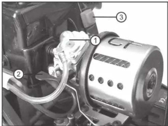
For starting, the carburettor has a manual pump that is used to transport fuel into the carburettor. This manual pump comprises a transparent rubber sphere (figure 4, item 1), which serves as sight glass for visual inspection of fuel supply to the carburettor at the same time.
- Connect the choke flap (see figure 4, item 2) by pushing the lever down.
- Actuate the manual pump (push rubber sphere several times) until the „gauge glass“ is completely filled up with fuel and the latter reaches the carburettor.
- Now pull the cable pull starter through repeatedly until you can hear the first ignition of the engine.
- Then open the choke flap again at once (lever horizontal) and pull the rope pull starter quickly until the engine starts up. Hold the model with one hand.
text_image
Technical diagram of a mechanical assembly with labeled parts including CT and numbered componentsFigure 4

Attention!
Do not pull out the cable starter all the way but only to a maximum of 3/4 of its length! Determine the rope length by slow extension without ignition! Never pull out the cable pull starter with force!
- When the motor goes out again right after the first start-up, close the chock flap and pull the cable pull starter through again until the motor runs again.
- Once the motor is running, release the cable pull starter and set the throttle/brake lever at the remote control transmitter to idle.
- Open the choke valve again (lever horizontal) and let the engine warm up for about 1 to 2 minutes.

Attention!
If the choke flap remains closed for too long or too much fuel was pumped into the combustion chamber and the crank housing, the mixture will over-fatten and the motor will flood. The cable pull starter can be operated only with increased force. Refrain from further start attempts and remove the excess fuel (see chapter 14) in order to prevent damaging the cable pull starter and the engine!
Figure 4, item 3 also shows the button for „Motor off“.
j) Controlling the Vehicle

The following figures are only to illustrate the functions and do not necessarily correspond to the design of the transmitter provided.
- Release throttle/braking lever, vehicle rolls to a halt (or does not move), lever is in neutral position
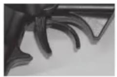
Figure 5
- Drive forwards, pull the throttle/brake lever towards the handle

Figure 6
- Drive forwards and then brake (vehicle slows down; does not roll to a halt slowly); push throttle/brake lever away from the handle without stopping
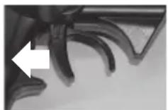
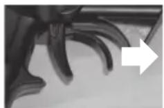
Figure 7

Move the throttle/braking lever for the drive function very cautiously and do not drive too fast at the beginning until you get used to the reactions of the car.
Do not make any quick and jerky movements with the operating elements of the remote control.
If the vehicle tends to pull towards the left or the right, set the steering trim on the transmitter accordingly (also see operating instructions of the remote control).
If the neutral position of the driving function is not correct (e.g. trimming slightly misadjusted), increased idle speed of the engine may cause the clutch to drag and wear prematurely (trimming is set to the full throttle direction) or the brake prevents rolling of the vehicle (trimming misadjusted towards brake). If you have one of these problems, correct the trimming settings for the driving function.
The model's two-stroke engine is air cooled. This means that the airstream has to cool down the engine (air cooling).
This is why you should try to avoid accelerating the vehicle with frequent, strong load changes (short throttle bursts from low rev range and jerkily lowering the revs). The short-term high speeds will strongly heat the engine without the corresponding cooling from airstream being ensured. As a result of overheating the engine, the piston may get stuck in the cylinder liner (piston gets stuck) and suddenly block the drive.
This could cause consequential damage to the entire drive train.
Stop driving immediately if the vehicle shows any unusual responses to the remote commands or if the vehicle does not respond at all.

This conduct may be caused by a weak receiver battery or batteries/rechargeable batteries in the transmitter.
A coiled telescopic aerial, disturbances on the radio channel or frequency band used (e.g. other models, radio transmissions from other devices), too large or a distance between the transmitter and vehicle or adverse transmission/reception conditions could also be a cause for unusual responses of the vehicle.
After a drive, wait for at least 5 - 10 minutes until motor and the entire drive (exhaust, clutch, etc.) have cooled down sufficiently before driving the vehicle again.
k) Stopping the Vehicle
To stop driving, proceed as follows:
- Let go of the throttle/brake lever on the transmitter so that it goes into neutral position, and let the vehicle run out.
- After the vehicle stands still, push the red button at the motor block above the cable pull starter (also see figure 4, item 3) and switch off the motor by this.

Never touch the wheels or the drive mechanism, and make sure you do not move the throttle/brake lever at the transmitter! Do not hold the vehicle at its wheels!
- Switch off the receiver power supply.
- Switch off the transmitter last.

Attention!
The motor and drive parts (e.g. exhaust) grow very hot in operation! Do not touch these parts immediately after operation. Danger of burns!
9. Vehicle Settings
a) Setting the Camber
The camber is the inclination of the wheel level as compared to the vertical.
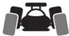
Figure 8a
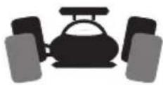
Figure 8b
Negative inclination Positive inclination
(Top wheel edge points inwards) (Top wheel edge points outwards)

The setting of the wheel is exaggerated in the two figures in order to make the difference between negative and positive cambers more obvious. The setting on the model vehicle should of course not be as extreme as shown!
- A negative inclination of the front wheels increases the lateral cornering powers of the wheel when driving through bends, the steering reacts more directly and steering forces are reduced. At the same time, the wheel is pushed onto the axle leg in the direction of the axle. This balances out axial bearing clearance, the driving behaviour is calmer.
- A negative inclination of the rear wheels reduces the tendency of the rear of the vehicle to swerve in bends.
- Setting a positive camber on the other hand reduces the cornering force of the wheels and should not be used.
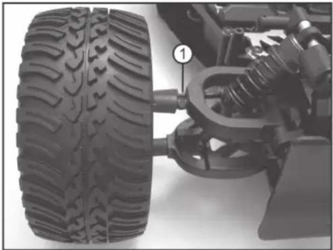
Setting Front Axle Camber:
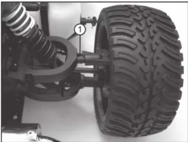
For setting the camber, turn the screw (1) of the upper transverse link.
Because this screw has a left and right hand thread at either end, the transverse link does not need to be dismantled for the camber to be adjusted.
natural_image
Close-up of a vehicle tire assembly with attached suspension components (no visible text or symbols)Figure 9
Setting Rear Axle Camber:
For setting the camber, turn the screw (1) of the upper transverse link.
Because this screw has a left and right hand thread at either end, the transverse link does not need to be dismantled for the camber to be adjusted.
natural_image
Close-up of a vehicle chassis with visible tire, suspension, and mounting bracket (no text or symbols)Figure 10
b) Setting the Alignment
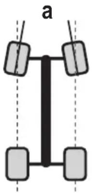
Wheel alignment (toe-in = figure „a“, toe-out = figure „b“) describes the relation of the wheel level to the driving direction.
The tyres are pushed apart in the front by rolling friction when driving. Therefore, they are no longer precisely parallel to the driving direction. To compensate, the tyres of the stationary vehicle can be adjusted so that they point slightly inwards. This toe-in improves lateral cornering of the tyres and leads to a more direct response to steering.
If a milder response to steering is desired, this can be achieved accordingly by adjusting a toe-out, i.e. the wheels of the stationary vehicle point outward. An alignment angle of 0^ on the front axle ensures the best driveability on almost any ground.
natural_image
Simple diagram of a vertical structure with four rectangular blocks and dashed vertical lines, labeled 'a' (no text or symbols within the diagram itself)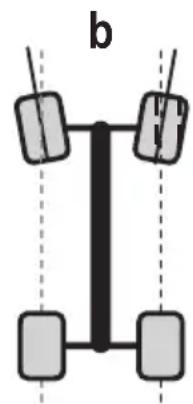
natural_image
Pure diagram of a vertical structure with four rectangular blocks and dashed vertical lines, no text or symbols present.Figure 11

An alignment angle of more than 3^ toe-in (a) or toe-out (b) will lead to handling problems and decreased speed. It will also increase tyre wear.
The figure above shows a strongly over-emphasised setting. It is only used for showing the difference between toe-in and toe-out. If such a setting is used for the vehicle, it will be very difficult to control!
Setting the alignment:
natural_image
Close-up of a vehicle chassis with visible tire, suspension components, and numbered annotation (1) — no readable text or symbols beyond the label.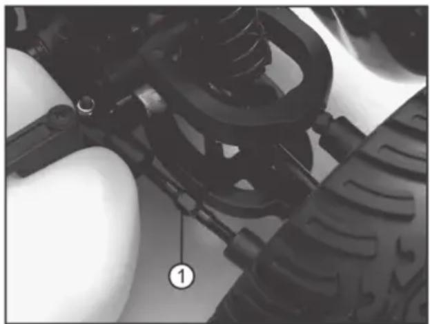
natural_image
Close-up of a mechanical assembly with visible springs and components, no text or symbols presentFigure 12: Front axle Figure 13: Rear axle
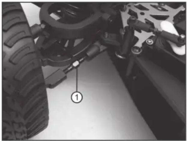
For the front axle, alignment can be set by turning the adjustment screw (1). Because the adjustment screw has a left and right hand thread at either end, it does not need to be dismantled to be adjusted.

Turn both adjustment screws (1) evenly (left and right front wheel). Otherwise, you need to adjust the trim of the transmitter or even correct the steering servo control (e.g. adjust servo rod or attach servo arm to the servo differently).
c) Adjusting the Steering Geometry
Servo defects are caused by stiff linkage or mechanical parts (e.g. by contamination or rust) as well as by asymmetrical and therefore non-linear geometric steering settings. Therefore, you need to check the following items in your model during driving and perform any required corrections.
These measures warrant stronger control operation that is faster under load and in particular even to the left and right. When making settings, always observe that the servo does not run to block.
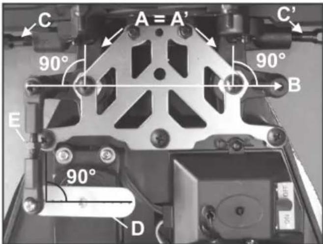
The right-angle steering levers A and A' must be precisely parallel and therefore aligned at 90° to line B. Line B is precisely at 180° (vertical) to the driving direction.
If the front wheels are not set precisely to neutral (straight) after correction of the steering lever position, use track rods C and C' to set the neutral position of the wheels (track).
Also observe the notes in chapter 9. b).
The servo output lever of steering servo D must be aligned at precisely 90^ of the servo housing when the transmitter is set to the neutral position (trimming also to 0).
If necessary, disassemble the servo lever and attach it again offset. Light deviations can be set by trimming the transmitter.
text_image
C A = A' 90° 90° B E 90° DFigure 14
When the steering levers and servo output levers are set precisely as described above, the track rod E may have to be shortened for the wheels to be set to straight driving again.
d) Setting the Shock Absorbers
text_image
Labeled diagram of a vehicle chassis showing tire, suspension components, and numbered parts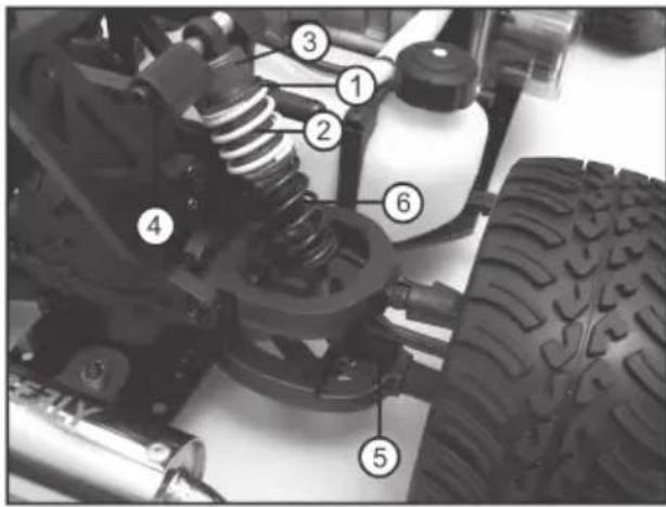
text_image
Labeled mechanical assembly diagram showing components like springs, tires, and a bottle with numbered partsFigure 15: Front axle Figure 16: Rear axle
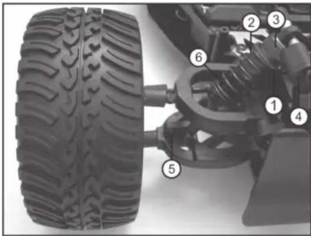
The spring-pre-tension at the upper end of the shock absorber can be adjusted by turning a knurled nut (1). Ensure that the shock absorber body (2) does not turn along and is turned from the shock absorber cap (3) by this (oil loss threatens).
The shock absorbers at the vehicle's front and rear vehicle axles can be mounted in different positions at the lower transverse link (5) and at the damper bridge (4). The manufacturer has, however, already chosen the best position; therefore, only professional drivers should change these.
Always set the shock absorbers for one axle evenly (at the left and right wheels of the front or rear axle). Otherwise, driving behaviour will be influenced negatively.
Always ensure correct attachment of the dust protection rubbers inside the springs (6).

Optional accessories (not included in the delivery; can be ordered separately) that can be used include springs with a different stiffness or damper oil of a different viscosity for filling the shock absorbers.
e) Setting the Servo Saver
The steering of the vehicle is designed as an axle leg steering.
The pivoting movement of the servo control lever affects one arm of the servo saver via the steering linkage.
The servo saver consists of two right-angled levers (1 and 2), which are not rigidly coupled but can be moved against each other via a spring in one level with the steering linkage.
The second lever arm of the servo saver moves the steering plate which in turn causes the steering deflection of both front wheels via the two track rods.
When hard shocks are transmitted from the wheels into the steering mechanics during operation, they are not immediately transmitted to the steering servo, but absorbed by the resilient connection of the two lever arms of the servo saver.
The effect of the servo saver can be adjusted with a knurled nut (3) by modifying the spring contact pressure on the two lever arms.
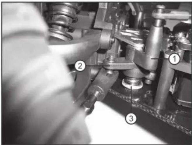
text_image
Technical diagram of a mechanical assembly with numbered components, likely a valve or pump mechanism.Figure 17

When this is set too soft, even light impacts against the wheel will cause the two servo saver arms to twist, which will negatively influence steering accuracy and track during driving.
However, if it is set too tightly, the servo drive may be damaged because impacts against the wheels are passed on to the wheels unfiltered.
10. Motor Settings
The carburettor is perfectly pre-adjusted for the first runs ex works. A rich carburettor setting is used to supply the motor sufficiently with lubrication in the run-in phase. This is shown by strong white smoke development from the exhaust.
The rich carburettor setting should be maintained for the first 2 - 3 tank fillings. Additionally, do not use any long full-throttle phases and run in the motor carefully with different speeds.
a) General Setting of the Carburettor
Depending on mixture used, spark plug, muffler and ambient conditions like barometric pressure and humidity, small changes in the carburettor setting may be required. The fine settings of idle and full throttle are only possible with the engine well run in.
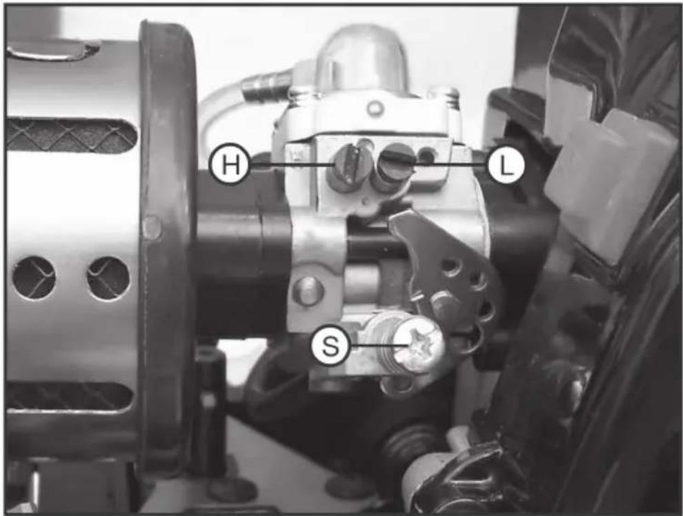
text_image
H L SFigure 18
L Idle mixture regulating screw
H Main nozzle needle
S Setting screw for idling speed
b) Setting the Idle Mixture Adjustment Screw (L)
- Put the motor to operating temperature by driving.
- If the motor does not accept throttle well, the idling mixture is too lean. Turn the idle mix adjusting screw anticlockwise (towards the left) to make the mix richer.
Adjust the setting gradually by about 1/8 turns of the idle mix adjusting screw anti-clockwise. - If the motor only accepts throttle stuttering and under strong development of smoke, the mixture is too rich. Twisting clockwise (to the right) makes the mixture leaner (the fuel share is reduced).
Adjust the setting gradually by about 1/8 turns of the idle mix adjusting screw clockwise.
c) Setting the Main Nozzle Needle (H)
- Lift the actuated axis from the bottom and drive the engine at operating state temperature at full throttle for a short time.
- The full throttle mixture at the main nozzle needle can now be set in steps of 1/8 turn.
Turn the main nozzle needle clockwise if the mix should be leaner.
Anticlockwise to make the mix richer (to increase the proportion of fuel).
- For a long motor service life, prefer a slightly rich carburettor setting to set the main nozzle needle.
For this, twist the main nozzle needle (H) slowly in small steps so that the engine reaches its maximum speed briefly after the control signal „full throttle“ and runs smoothly without stuttering.
Then turn the main nozzle needle counter-clockwise by about 1/8 turn to increase the fuel share (= rich carburettor setting).
- After each engine running (tank filling), allow for a sufficient cooling stage (approx. 10 min).

Attention!
It is always extremely important not to make the mix too lean! Observe that the engine is lubricated by the oil in the fuel.
Too little oil in the mix (= lean carburettor settings) will cause the engine to overheat and the piston to seize due to defective lubrication. During operation, a slight white smoke vane should be visible from the exhaust at all times. If not, stop the engine at once and enrich the mix. Also make sure that sufficient air circulates around the cylinder head in order to avoid overheating. The best engine operating temperature is approx. 100 - 120°. Check the temperature with an infrared thermometer.
You can tell that the engine is run in when it can be cranked up in cold state without spark plug and without noticeable resistance. Only now must the engine be operated at full output.
d) Setting the Idling Mixture Speed (S)
- Turn the setting screw for idling speed (S) clockwise to increase the idling speed.
- Turning the setting screw counter-clockwise decreases the idling speed.

Set the idling speed with the engine still warm from operation so that the engine still runs securely. Avoid too-high idling speed because this will cause the clutch to drag continually and speeds up wear.
e) Recovering the Factory Settings
Idle Mixture Adjustment Screw (L):
As basic setting, unscrew the idle mix adjusting screw by 1.25 rotations.
- Carefully turn the screw in without applying force until it is flush.
- Now unscrew the needle again by 1.25 rotations.
Main nozzle needle (H):
The basic setting of the main nozzle needle is 1.75 rotations.

If the main nozzle needle is turned in too firmly, both the needle and the needle seat in the carburettor may be destroyed! Loss of guarantee/warranty!
11. Cleaning and Maintenance

If you have driven the vehicle before, let all parts (e.g. motor, exhaust, etc.) cool down completely first.
Clean the whole vehicle of dust and dirt after driving, e.g. with a long-haired clean brush and a vacuum cleaner. Compressed air aerosols can also be helpful.

Do not use cleaning aerosols or conventional household cleaners. This may damage the electronics and lead to discolouration of the plastic parts or the body.
Never wash the vehicle with water, e.g. using a high-pressure cleaner. This will destroy the engine and the receiver as well as the servos. The vehicle must not become damp or wet!
A soft cloth, slightly dampened, can be used to wipe the car body. Do not rub too hard to avoid scratch marks.
At appropriate intervals, you should perform maintenance work and function checks on the vehicle. This ensures trouble-free operation and road-worthiness for a long time.
Motor vibrations and shocks during driving can loosen parts and screw fittings.
Therefore, check the following items before and after driving:
- Tight fit of wheel nuts and of all vehicle screw fittings
- Servo attachment
- Glue-connections of tyres and rims or tyre condition
- Attachment of all cables (they must not get into movable parts of the vehicle)

Also check the model for damage before each use. If you find any damage, the car may not be used anymore and has to be taken out of operation.
Only original spare parts must be used to replace worn vehicle parts (e.g. tyres) or defective vehicle parts (e.g. a broken transverse link).
Check, the following positions regularly after several drives:
- The air filter must be oiled, clean and undamaged to filter out even the finest dust, e.g. in a dusty environment.
- All moveable parts and parts with bearings must be lubricated with a low viscosity machine oil or spray grease after cleaning of the model or several drives.
- Check looks and contact distance of the spark plug.
Spark plugs wear, especially in the running-in phase. Therefore, we recommend that you always keep some spark plugs at hand for replacement.
Only use spark plugs of type „CMR 7H“! Wrong or worn spark plugs will cause the engine to run incorrectly and impairs reconciliation. Installation and replacement of the spark plug requires a spark plug wrench (lug wrench SW10). The ideal electrode distance of intact spark plugs is 0.7 mm.
- Check the carburettor and brake linkage.
With the throttle/brake servo (1) set to neutral, the carburettor linkage rod (2) must push slightly onto the mechanical stop of the rudder horn via the carburettor throttle flap.
• The brake linkage (3) must not affect the brake lever (4) and therefore the brake yet.
- If the brake function is operated at the transmitter, the rudder horn moves towards the arrows. The throttle linkages are pulled even more strongly towards the mechanical stop at the carburettor (also see figure 18) by the installed spring. The motor speed must not decrease. If this is the case, the front adjustment ring must be adjusted (push towards the carburettor).
- At the same time, the throttle lever (4) is moved and operates the brake. Brake linings are subject to wear. After a certain operating duration, the brake effect will reduce depending on driving manner. The adjustment screw (5) can be used to adjust the linkage until the usual brake effect is achieved again.
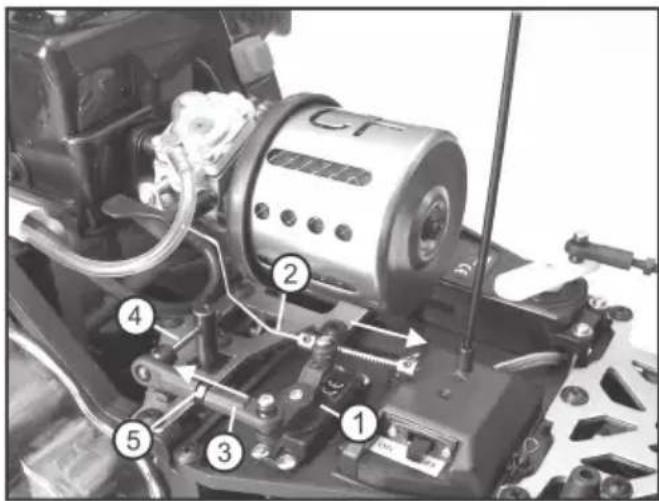
text_image
Labeled mechanical assembly diagram showing components numbered 1 to 5 for assembly or maintenance reference.Figure 19
12. Disposal
a) General Information
Electronic devices must not be disposed of in the domestic waste!
At the end of its service life, dispose of the product according to the relevant statutory regulations.
b) Batteries and Rechargeable Batteries
You as the end user are required by law (Battery Ordinance) to return all used batteries/rechargeable batteries. Disposing of them in the household waste is prohibited!
Batteries and rechargeable batteries containing hazardous substances are marked with adjacent symbol to indicate that disposal in the household waste is prohibited. The descriptions for the respective heavy metal are: Cd=cadmium, Hg=mercury, Pb=lead (the designation is written on the battery/rechargeable battery, e.g. under the dust bin symbol depicted at the left).
You may return used batteries/rechargeable batteries free of charge at the official collection points of your community, in our stores, or wherever batteries/rechargeable batteries are sold.
You thus fulfil your statutory obligations and contribute to the protection of the environment.
13. Declaration of Conformity (DOC)
We, Conrad Electronic, Klaus-Conrad-Straße 1, D-92240 Hirschau, hereby declare that this product adheres to the fundamental requirements and other relevant regulations of the directive 1999/5/EC.

The compliance statement for this product is available at www.conrad.com.
14. Troubleshooting
Even though the model and the remote control system were built according to the state of the art, there may still be malfunctions or errors. For this reason, we would like to give you some information on how to deal with possible problems.
The model does not respond
- For 2.4 GHz remote control systems, the receiver must be taught to the transmitter. This process may be referred to by the terms of „Binding“ or „Pairing“. The teaching process usually was performed by the manufacturer already; however, it can, of course, also be done by you. Also observe the separately enclosed operating instructions for the remote control system.
- Is the receiver battery or are the batteries/rechargeable batteries in the transmitter discharged?
- Did you switch on the transmitter first and then the receiver power supply? Always observe this order!
- Is the receiver battery connected to the corresponding connection plug correctly?
- Is the vehicle too far away? With a fully charged receiver battery and fully charged batteries/rechargeable batteries in the transmitter, the range should be 100 m and more. The range can be decreased by outside influences, such as transmitters working on the same or an adjacent frequency, proximity to metal parts, trees, etc.
The position of transmitter and receiver aerial to each other very strongly influences range. It is best when both the transmitter and receiver aerial are vertical. If you point the transmitter aerial at the vehicle, the range will be very short! - Check the correct position of the servo plugs in the receiver. If the plugs are inserted rotated by 180^ , the servos will not work.
- Are the servo and speed controller plugs connected in the right orientation? If, however, the throttle controller and steering servo plugs are swapped, the throttle/brake lever controls the steering servo, and the wheel of the throttle servo controls driving.
▶ The motor does not start.
- Idling speed is set too low.
Set the neutral position on the transmitter correctly by using the trimmer for the driving function or trim towards idling speed increase. Check the adjustment rings at the throttle linkages for correct and tight fit.
- Was the choke set for starting?
- Was the choke set too long? The engine may have been flooded.
Remove the spark plug. Carefully dry the spark plug with compressed air. Hold a cloth above the engine cylinder and pull the cable pull starter several times to remove excessive fuel from the combustion chamber. Insert the spark plug again and start again without choke. If the motor does not start up again after the tenth attempt, try with the choke set again.
- Is the electrode distance of the spark plug correct (target: 0.7 mm)?
- Has the spark plug been in use for a longer time or may it be worn? In doubt, check the starting attempt with a new spark plug.
- Are all fuel lines OK? Is the manual pump used to suck off fuel?
The vehicle does not stop when the throttle/brake lever is released
- Idling speed is set too high. Set the neutral position on the transmitter correctly by using the trimmer for the driving function arm.
- When the trimming path isn't sufficient, adjust the idling speed screw at the carburettor.
▶ Vehicle slows down
- The drive is blocked by leaves, branches, etc.
- The carburettor setting is too lean (engine is weak and possible overheated). Set the carburettor richer.
- The air filter insert is contaminated. This makes the carburettor setting too rich (motor stutters and does not or only very slowly pick up speed). Clean or replace the air filter.
The steering servo shows only slight or no reaction; the range between transmitter and vehicle is very short
• The receiver battery is weak or discharged.
- Check the batteries/rechargeable batteries in the transmitter.
The vehicle doesn't drive in a straight line correctly
- Adjust the steering trimmer at the transmitter.
- Check the steering rods or wheel alignment setting.
- Did your car have an accident? If so, check the vehicle for any defective or broken parts and replace them.
▶ Steering works opposite to the way the turning wheel is turned at the transmitter
- Activate the steering reverse setting at the transmitter.
▶ Driving works opposite to the movement of the throttle/brake lever at the transmitter
Usually, the vehicle should drive forwards if you pull the throttle/brake lever at the transmitter towards the handle. Activate the driving reverse setting at the transmitter.
The steering is not functioning or is functioning incorrectly, steering lock too slight on the vehicle
- If the transmitter offers dual rate settings, check these settings (observe transmitter's operating instructions). If the dual rate setting is too low, the steering servo will no longer react.
The same applies for the so-called EPA setting (= „End-Point-Adjustment“, setting of the end positions for the servo path to protect the servo mechanics) if present at the transmitter. - Check the steering mechanics for loose parts; e.g. check if the servo arm is properly attached to the servo.
- The steering mechanics are stiff because of dirt or rust. Clean and lubricate the complete steering mechanics.
- The servo saver is set too weak.
15. Technical Data
Scale: 1:6
Receiver battery: ...... a 5-cell NiMH battery pack (rated voltage 6.0 V); not included, must be ordered separately
Drive: 2-stroke combustion engine, 26 ccm, 1.18 kW / 1.6 PS
Rear-wheel drive
ball-bearing drive
Differential in rear axle
front and rear axle camber can be set
front and rear axle track can be set
Suspension: .... independent wheel suspension with spiral spring/shock-absorber, adjustable
Dimensions (L x W x H): 750 x 445 x 270 mm
Tyre dimensions (W x ∅): 78 x 170 mm
Wheel base: 525 mm
Ground clearance: 55 mm
Weight (without rechargeable batteries): .10,490 g

Low deviations in dimensions and weight are due to production technical reasons.
Page
natural_image
Top-down view of a toy car showing front wheel, suspension components, and engine assembly (no visible text or symbols)Figure 1
natural_image
Mechanical assembly diagram showing a motor and gear assembly with no visible text or symbolsFigure 2
text_image
Technical diagram of a mechanical assembly with labeled parts including CT and numbered componentsFigure 4

Attention!
natural_image
Close-up of a vehicle tire and mechanical assembly with no visible text or symbolsFigure 9
natural_image
Close-up of a vehicle chassis with a large tire and spring assembly (no visible text or symbols)Figure 10
natural_image
Pure diagram of a vertical structure with four rectangular blocks and dashed vertical lines, no text or symbols present.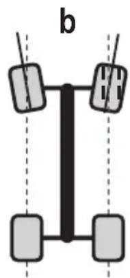
natural_image
Pure diagram of a vertical structure with four rectangular blocks and dashed lines, no text or symbols present.Figure 11

natural_image
Close-up of a vehicle's lower body and suspension system, showing tire, hoses, and mechanical components (no text or symbols visible)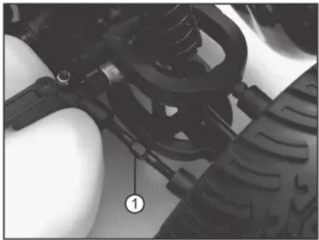
natural_image
Close-up of a mechanical assembly with visible springs and components, no text or symbols presenttext_image
Labeled diagram of a vehicle chassis showing tire, suspension components, and numbered parts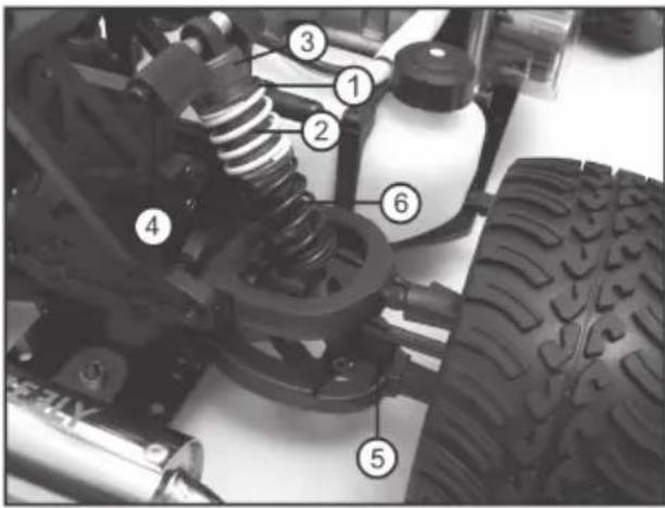
text_image
Labeled mechanical assembly diagram showing components like springs, tires, and a vehicle chassistext_image
Technical diagram of a mechanical assembly with numbered components labeled 1, 2, and 3Figure 17
text_image
Technical diagram of a mechanical assembly with numbered components, likely a motor or engine component.Figure 19
12. Élimination
a) Généralités
natural_image
Top-down view of a toy car chassis showing front wheel, suspension, and engine components (no text or symbols visible)Afbeelding 1
natural_image
Close-up of a mechanical assembly with a cylindrical component and wiring, no visible text or symbolsAfbeelding 2
text_image
Technical diagram of a mechanical assembly with labeled parts including CT and numbered componentsAfbeelding 4

Waarschuwing!
natural_image
Close-up of a vehicle tire assembly with attached suspension components (no visible text or symbols)Afbeelding 9
natural_image
Close-up of a vehicle chassis with visible tire, suspension, and mounting bracket (no text or symbols)Afbeelding 10
b) Instellen sporing
natural_image
Diagram of a vertical structure with four rectangular blocks connected by lines, labeled 'a' at top (no text or symbols within the diagram itself)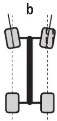
natural_image
Simple diagram of a vertical structure with four rectangular blocks and dashed vertical lines, labeled 'b' (no text or symbols within the diagram itself)Afbeelding 11

natural_image
Close-up of a vehicle's lower body and suspension system, showing tire, mechanical components, and a numbered annotation (1) — no readable text or symbols beyond the label.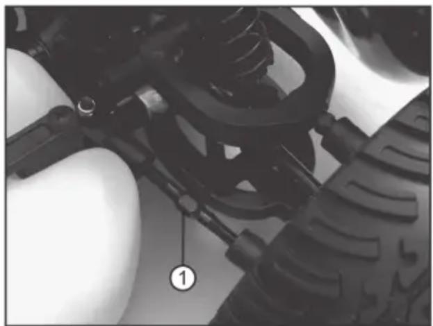
natural_image
Close-up of a mechanical assembly with visible springs and components (no text or symbols)text_image
Labeled diagram of a vehicle chassis showing tire, suspension components, and numbered parts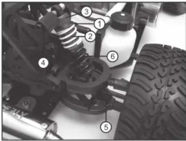
text_image
Labeled mechanical assembly diagram showing components like springs, tires, and a bottle with numbered partstext_image
Technical diagram of a mechanical assembly with numbered components labeled 1, 2, and 3Afbeelding 17

text_image
Labeled mechanical assembly diagram showing components numbered 1 to 5 for assembly or maintenance reference.Afbeelding 19
© Copyright 2013 by Conrad Electronic SE.
GB Legal Notice
These operating instructions are a publication by Conrad Electronic SE, Klaus-Conrad-Str. 1, D-92240 Hirschau (www.conrad.com).
All rights including translation reserved. Reproduction by any method, e.g. photocopy, microfilming, or the capture in electronic data processing systems require the prior written approval by the editor. Reprinting, also in part, is prohibited.
These operating instructions represent the technical status at the time of printing. Changes in technology and equipment reserved.
© Copyright 2013 by Conrad Electronic SE.
© Copyright 2013 by Conrad Electronic SE.
NL Colofon
© Copyright 2013 by Conrad Electronic SE.
V3_0413_01