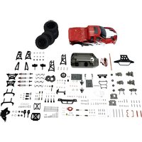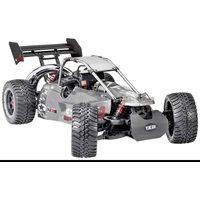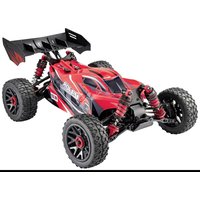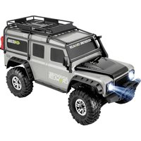
Cimera - Remote control toy Reely - Free user manual and instructions
Find the device manual for free Cimera Reely in PDF.


User questions about Cimera Reely
0 question about this device. Answer the ones you know or ask your own.
Ask a new question about this device
Download the instructions for your Remote control toy in PDF format for free! Find your manual Cimera - Reely and take your electronic device back in hand. On this page are published all the documents necessary for the use of your device. Cimera by Reely.
USER MANUAL Cimera Reely
GB Operating Instructions
1:10 Electric Monstertruck
"Cimera" 4WD RtR
Item no. 2304801 (super combo set) Page 32 - 61
F Notice d'emploi
natural_image
Close-up of a mechanical component with labeled parts A and B, showing internal structure and wiring (no readable text or symbols beyond labels)natural_image
Close-up of a black mechanical component with curved arms (no visible text or symbols)natural_image
Close-up of a black mechanical component with a white arrow pointing to it (no visible text or symbols)natural_image
Close-up of a car tire with a curved tire and arrow pointing to it (no visible text or symbols)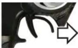
natural_image
Close-up of a car wheel with a curved handle and an arrow pointing to it (no text or symbols visible)natural_image
Close-up of a mechanical component with a curved arrow pointing left (no visible text or symbols)Vorwärts fahren
natural_image
Close-up of a car wheel with a black curved handle and an arrow pointing to it (no text or symbols visible)Bremsen
natural_image
Close-up of a black mechanical component with curved arms (no visible text or symbols)natural_image
Close-up of a black mechanical component with a curved arrow pointing to it (no text or symbols visible)Rückwärts fahren
natural_image
Mechanical assembly diagram showing a vehicle's suspension system with labeled component A (no text or symbols beyond label)natural_image
Diagram of a vertical structure with four rectangular blocks connected by a central black line, labeled 'A' at top (no text or symbols within the diagram itself)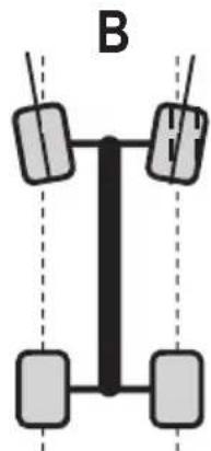
natural_image
Simple diagram of a vertical structure with four rectangular blocks and two horizontal lines, labeled 'B' (no text or symbols within the diagram itself)
natural_image
Mechanical assembly diagram showing a mechanical component with springs and shafts (no text or symbols visible)natural_image
Mechanical assembly diagram showing a vehicle suspension system with labeled component A (no text or symbols beyond label)natural_image
Mechanical assembly diagram showing a spring-loaded component with labeled parts A and B (no text or symbols beyond labels)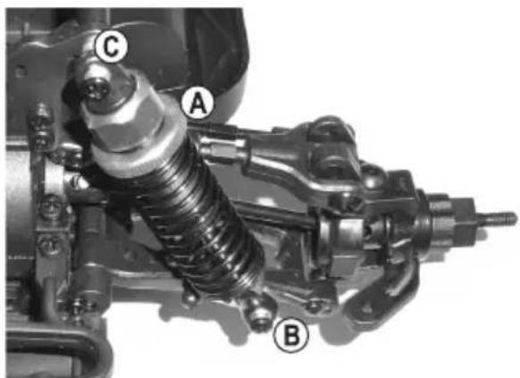
text_image
A B Ctext_image
Technical diagram of a mechanical assembly with labeled parts A, B, C, D, and Ewww.conrad.com/downloads
- Introduction....34
- Explanation of symbols....34
- Intended use....35
- Delivery content....35
- Required Accessories 36
- Safety instructions ....37
a) General information....37
b) Operation....38
c) Driving the vehicle 38
- Battery safety information....40
a) General information....40
b) Additional information about lithium rechargeable batteries....41
- Charging the drive battery for the vehicle 43
- Operation....44
a) Removing the bodywork....44
b) Inserting batteries/rechargeable batteries in the transmitter 44
c) Putting the transmitter into operation....44
d) Inserting the drive battery in the vehicle....44
e) Connecting the drive battery to the speed controller 45
f) Switching on the speed controller....45
g) Attaching and fastening the car body 46
h) Controlling the vehicle 47
i) Stopping the vehicle 48
- Programming the speed controller....49
a) Adjusting the neutral and full throttle setting....49
b) Programming additional features....50
c) Resetting the speed controller....52
- Adjustment options on the vehicle....53
a) Setting the camber 53
b) Setting the alignment....54
c) Adjusting the shock absorbers 55
Page
- Cleaning and care....56
a) General information....56
b) Before and after each trip....56
c) Changing a tyre 57
- Disposal 58
a) Product 58
b) Batteries 58
- Declaration of Conformity (DOC)....58
- Troubleshooting....59
- Technical data....61
a) Vehicle....61
b) Remote control system....61
c) LiPo charger 61
d) LiPo battery 61
1. Introduction
Dear customer,
Thank you for purchasing this product.
This product complies with the statutory national and European requirements.
To maintain this condition and to ensure safe operation, the user should always follow the instructions in this manual.

These operating instructions are part of this product. They contain important information on setting up and using the product. Remember this if you pass on the product to any third party.
Keep these operating instructions in a safe place for future reference.
All company and product names are trademarks of their respective owners. All rights reserved.
If there are any technical questions, please contact: www.conrad.com/contact
2. Explanation of symbols

This symbol is used to highlight important information in these operating instructions. Always read this information carefully.

This symbol indicates special information and advice on how to use the product.
3. Intended use
The product is an all-wheel model car which can be radio-controlled via the enclosed wireless remote control. The control functions are forwards/backwards/left/right (each one continuous).
The integrated brushless motor is controlled via an electronic speed controller and the steering via a servo.
The vehicle (chassis and bodywork) is ready-to-run.
A suitable LiPo drive battery and a LiPo charger as well as 4 AA/Mignon batteries for the transmitter are included.
The product is not a toy and must be kept out of reach of children under 14 years of age.

Always follow the safety information in these operating instructions. They contain important information on how to handle the product safely. Read the instructions carefully before using the vehicle for the first time.
Failure to observe the instructions can result in numerous hazards (e.g. injury).
4. Delivery content
- Ready-to-run car
• Transmitter (remote control)
• 3-cell LiPo drive battery (nominal voltage 11.1 V)
• 4 AA/Mignon batteries for the transmitter - LiPo charger
- Power cord
- Operating instructions for the vehicle
- Operating instructions for the remote control system (transmitter/receiver) on CD
- Operating instructions for the LiPo charger on CD
Up-to-date operating instructions
Download the latest operating instructions at www.conrad.com/downloads or scan the QR code on this page. Follow the instructions on the website.

5. Required Accessories
The vehicle comes with a 3-cell LiPo rechargeable battery, a LiPo battery charger and 4 AA batteries for the remote control. No additional accessories are required.
However, for best results, we also recommend the following components:
- One or more additional vehicle batteries (to enable the vehicle to continue after a short pause to cool the engine and the speed controller)
- Replacement batteries (4x AA) for the remote control (in case the batteries in the remote control become depleted when you are driving the vehicle)
- Spare tyres (in order to quickly change worn/damaged tyres)
- Stand (for test runs and easier maintenance)
- Other tools (e.g. screwdriver, needle-nosed pliers, hex key, wrench)
- Compressed air spray (for cleaning)
- Thread-locking fluid (to fix loose screw connections)
- Carry bag
To view the replacement parts lists, visit www.conrad.com and go to the Downloads section for your product.
6. Safety instructions

Damage caused due to failure to observe these instructions will void the warranty. We shall not be liable for any consequential damages.
We shall not be liable for damage to property or personal injury caused by incorrect handling or failure to observe the safety information! Such cases will void the warranty/guarantee.
Normal wear and tear during operation (e.g. worn tyres, worn-out gear wheels) and accidental damages (e.g. broken suspension arms, damaged chassis etc.) are excluded from the guarantee and warranty.
Dear Customer, these safety instructions are not only for the protection of the product but also for your own safety and that of other people. This is why you should read this section very carefully before using the product!
a) General information
Caution, safety hazard!
Operating the model may cause damage to property and/or individuals. Therefore, make sure that you are sufficiently insured when using the model, e.g. by taking out private liability insurance. If you already have such a policy, check with your insurance company that the use of this model is covered by the policy.
- The unauthorized conversion and/or modification of the product is prohibited for safety and approval reasons.
- The product is not a toy and must be kept out of reach of children under 14 years of age.
- Do not leave packaging material unattended, as it may become dangerous toy for children.
- If you have any questions that are not answered by these operating instructions, contact us (see section 1 for contact information) or an experienced technician.
The operation and the handling of remote control model cars must be learned! If you have never steered such a vehicle, drive especially carefully and get used to the reactions of the car to the remote control commands first. Be patient!
Do not take any risks when using the product! Your own safety and that of your environment depends completely on your responsible use of the model.
- Proper use of the vehicle requires occasional maintenance work and repairs. For example, the tyres will suffer wear during operation, or there could be "accidental damage" due to driver error.
Only use genuine spare parts for the required maintenance and repair work!

b) Operation
- The instructions for the remote control system and charger are included separately. Always follow all the safety information as well as all other information! Numerous hazards are associated with improper handling of the battery charger.
- Only use suitable drive batteries for the vehicle. Never operate the speed controller using a power adaptor, not even for test purposes.
- This vehicle is only suitable for use with a LiPo drive battery with max. 3 cells (nominal voltage 11.1 V).
When using a drive battery with more cells, there is a danger of fire resulting from the speed controller overheating. In addition, the vehicle's drive will be overloaded and thus damaged (e.g. differential). This will void the warranty. - When putting the device into operation always turn on the transmitter first. Only then can the drive battery of the vehicle be connected to the speed controller and the speed controller be switched on. Otherwise, the vehicle can react unpredictably.
Follow the steps below:
- Place the vehicle on a suitable support before connecting the drive battery so that the wheels can turn freely.
- Switch off the control unit.
- Switch on the transmitter, if you haven't done it yet already. Check that it functions correctly (e.g. transmitter operating display).
- On the transmitter, set the trim for the throttle/brake function to the central position.
- Connect a fully charged drive battery to the speed controller ensuring that the polarity is correct (red cable = positive/+, black cable = negative/-).
- Only now turn on the speed controller. Wait for a few seconds until the speed controller has completed its self-test.
- Check that the vehicle reacts to the remote control commands as expected (steering and drive) before removing it from the support and placing the wheels on the ground.
- If the drive does not perform as expected, follow the instructions in section 14.
c) Driving the vehicle
- Improper use can cause serious injury and damage to property! Only drive as long as you have visible contact to the model. This is why you shouldn't drive at night.
- Only drive when your ability to react is unrestrained. Tiredness, or the influence of alcohol or drugs, can cause incorrect responses; just as with real vehicles.
- Please note that this model car must not be driven on public roads or streets. Do not use the vehicle on private land without the landowner's permission either.
• Do not drive towards animals or people! - Avoid driving at very low outdoor temperatures. Plastic parts lose their elasticity at cold temperatures, which means a minor accident could lead to major damage.

- Do not drive in the case of thunderstorm, under high-voltage power lines or in the proximity of radio masts.
• Always leave the transmitter turned on while the vehicle is in operation. - When turning off the vehicle, always switch off the vehicle's speed controller first and then completely disconnect the drive battery from the speed controller. It is only now that the transmitter may be turned off.
- If the batteries (or rechargeable batteries) in the transmitter are weak, the transmission range decreases. Exchange the batteries or rechargeable batteries for new ones.
- When the drive battery in the vehicle is weak, the vehicle gets slower or no longer responds correctly to the transmitter.
The drive battery in the vehicle is not just used to supply the motor via the speed regulator. The speed controller also generates the voltage/current required for the receiver and the steering servo.
For this purpose, the speed controller has an integrated BEC ("Battery Eliminator Circuit", electronic circuit for the direct supply of voltage to the receiver without additional receiver battery).
If the voltage in the drive battery is too low, the voltage in the receiver may also drop, causing the vehicle to no longer respond to the steering commands from the transmitter.
In this case, stop driving the vehicle immediately (switch off the speed controller, disconnect the drive battery from the vehicle, switch off the transmitter). Then replace the vehicle drive battery or recharge the drive battery.
- The motor and drive as well as the speed controller and drive battery of the vehicle get hot during operation. Wait approx. 5 to 10 minutes before each battery change.
- Allow the drive battery to cool down completely before charging.
- Do not touch the motor, the speed controller or the rechargeable battery until they have cooled down. Burn hazard!
7. Battery safety information

Although the use of batteries is part of our everyday lives nowadays, batteries still present numerous safety hazards. Compared with conventional NiMH rechargeable batteries, LiPo rechargeable batteries have a high energy content. For this reason, it is essential to comply with safety regulations to prevent the risk of a fire or explosion.
Always observe the following information and safety warnings when handling (rechargeable) batteries.
a) General information
- Keep batteries out of the reach of children. (Rechargeable) batteries must be kept out of reach of children.
- Do not leave batteries lying around as they might be accidentally swallowed by children or pets. Seek immediate medical advice if a battery is swallowed.
- Batteries/rechargeable batteries must never be short-circuited, taken apart or thrown into fire. There is a risk of explosion!
- Leaking or damaged batteries can cause burns if they come into contact with your skin, therefore always use suitable protective gloves to avoid burning your skin.
- Liquids leaking from batteries/rechargeable batteries are very chemically aggressive. Objects or surfaces coming into contact with these liquids could be severely damaged. Always store batteries in a suitable location that is not prone to damage.
- Do not recharge normal, non-rechargeable batteries. This may cause a fire or explosion! Non-rechargeable batteries are only designed to be used once and must be disposed of properly when they are empty. Only recharge compatible rechargeable batteries using a suitable charger.
- If you do not plan to the use the model vehicle for an extended period, remove the batteries from the transmitter to prevent them from leaking and causing damage. Disconnect the battery from the model completely and remove it from the model. Keep the remote control batteries and drive battery in a cool, dry place out of the reach of children.
Install a smoke detector in the room. Batteries present a fire hazard and may generate toxic fumes. This applies in particular to model toy batteries, which are subjected to high charging/discharge currents and vibrations.
- Always exchange the entire set of batteries in the transmitter. Do not mix full batteries with half-full ones. Always use batteries or rechargeable batteries of the same type and manufacturer. Never mix disposable batteries with rechargeable batteries.
- When inserting batteries into the transmitter or connecting the battery to the model, pay attention to the polarity markings (plus/+ and minus/-) to ensure that the batteries are connected in the correct polarity. Should you connect the battery incorrectly, not only will the model be damaged but also the battery. This may cause a fire or explosion!
-
Do not expose the charger or drive battery to extremely high/low temperatures or direct sunlight.
-
Batteries must not become damp or wet. The same applies for the charger that comes with the product. The charger must only be used in dry, enclosed indoor areas. Moisture on the charger may cause a fatal electric shock! The battery may also cause a fire or explosion!
Lithium rechargeable batteries (e.g. LiPo batteries) contain chemicals that are very sensitive to moisture! - Disconnect the drive battery from the model completely before connecting it to the charger. Never leave the battery connected to a speed controller when it is charging. This may damage the charger, speed controller or the battery! Always remove the battery from the model before recharging it.
- Place the charger and rechargeable drive battery on a non-flammable, heat-resistant surface (e.g. stone tiles). Keep the charger and battery away from flammable objects. Maintain a sufficient distance between the charger and the drive battery. Never place the drive battery on top of the charger.
- Do not charge batteries when they are still hot (e.g. due to a high discharge current in your model). Allow the battery to cool down to room temperature before charging it.
- Ensure that there is sufficient ventilation, as the battery and charger may heat up during the charging process. Never cover the charger or the rechargeable battery!
- Never leave batteries unattended when they are charging. Inspect the charger at regular intervals to ensure that the battery is not overheating or expanding. If this is the case, it indicates an imminent risk of a fire or explosion. If the battery overheats or starts to expand, disconnect it from the charger immediately and take it to a location where it will not cause any additional damage if it explodes or catches fire (e.g. outdoors).
- Disconnect the battery from the charger when it is fully charged.
- Never damage the casing of a rechargeable battery.
- Never charge damaged, leaking or deformed batteries. This may cause a fire or explosion! Discontinue use immediately and dispose of the battery in an environmentally friendly manner.
- Rechargeable batteries should be charged regularly (approx. once every 2 - 3 months) to prevent them from overdischarging. This may result in permanent damage and render the batteries useless.
LiPo batteries usually retain their charge for several months. However, if the batteries overdischarge, this will result in permanent damage and render them useless.
b) Additional information about lithium rechargeable batteries
Modern lithium rechargeable batteries have a significantly higher capacity than NiMH and NiCd batteries and are also significantly more lightweight. This makes lithium batteries (especially Lithium Polymer batteries) particularly suitable for use in model making.
However, LiPo batteries require particular care during charge/discharge, operation and handling.
The following sections provide an overview of the potential hazards associated with LiPo batteries and explain how these hazards can be avoided to ensure a long lifespan for such batteries.
- The casing of many lithium batteries is made of one single thick film, which is very sensitive. Do not dismantle, drop or insert any objects into lithium batteries. Do not apply mechanical loads or pull on the battery's connection cables. This may cause a fire or explosion!
Always observe these instructions when inserting or removing a battery from your model.
- Ensure that the battery does not overheat during use, recharging, discharging, transport or storage. Do not place rechargeable batteries next to sources of heat (e.g. a speed controller or motor) or expose them to direct sunlight. This may cause the battery to overheat, which can cause a fire or explosion! The temperature of the battery must not exceed +60 °C. (If necessary follow additional manufacturer specifications for the battery!).
- If there are any signs of damage or the outer casing starts to swell or expand, discontinue use immediately. Do not charge it any more. This may cause a fire or explosion!
Exercise caution when handling the damaged battery and use suitable protective gloves. Dispose of the battery in an environmentally friendly manner.
Never store such batteries in an apartment or in a house/garage. Damaged or swollen lithium batteries may suddenly catch fire.
- Always use a compatible charger to charge lithium batteries and/or always use the suitable charging method. Do not use NiCd, NiMH or lead-acid battery chargers, as these may cause a fire or explosion! Always select the correct charging method for your rechargeable battery.
- Always use a balancer when charging a lithium battery with more than one cell (the included battery charger comes with a built-in balancer).
- The charge rate for LiPo batteries must not exceed 1 C (or the value stated in the battery instructions). This means that the charging current must not exceed the battery capacity (e.g. battery capacity = 1000 mAh, max. charging current = 1000 mA = 1 A).
- The discharge current must not exceed the value stated on the battery.
For example, if "20 C" is printed on the LiPo battery, the maximum discharge current is 20 times the battery's capacity (e.g. battery capacity = 1000 mAh, max. discharge current = 20 C = 20x 1000 mA = 20 A).
Exceeding the maximum current may cause the battery to overheat or become deformed, which can lead to a fire or explosion!
However, the printed value (e.g. 20 C) generally does not indicate the continuous current but the maximum current that the battery can deliver for a short period. The continuous current should not be higher than one half of the stated value.
- Do not allow the individual cells of a lithium battery to become fully discharged. Overdischarging of a lithium battery may destroy the battery or cause permanent damage.
If the model does not have overdischarge protection or a low battery indicator, stop using it before the battery becomes empty.
8. Charging the drive battery for the vehicle
- The vehicle comes with a 3-cell LiPo rechargeable battery and a LiPo battery charger. Refer to the charger instructions before charging the battery.

Warning!
LiPo battery charger should only be used to charge a LiPo vehicle battery. Attempting to charge a NiMH battery with the LiPo battery charger may cause a fire or explosion!
LiPo batteries must be charged with a suitable LiPo battery charger (similarly, NiMH batteries must be charged with a NiMh battery charger). Always ensure that you use the correct type of battery charger.
- The vehicle battery is empty when the product is shipped and must be charged. Several complete discharge and charge cycles are required to ensure that the battery reaches it maximum performance.
- NiMH and LiPo batteries can be recharged when they are partially discharged. They do not normally need to be fully discharged in advance.
- High-quality vehicle batteries have a higher capacity, which results in a longer battery life. They also have a higher output voltage, which provides more power for the motor for enhanced acceleration and higher speeds.
- The vehicle battery heats up when charging/discharging (i.e. when driving the vehicle). Wait until the battery has reached room temperature before charging it. The same applies after the battery has finished charging. Allow the battery to cool down before connecting it to the vehicle.
- Only use a charger that is designed for the type of vehicle battery used (e.g. NiMH or LiPo).
• Always remove the battery from the vehicle before recharging it.
9. Operation
a) Removing the bodywork
Remove the four safety clips on the upper side of the vehicle and lift the body off upwards.
b) Inserting batteries/rechargeable batteries in the transmitter
Open the battery compartment on the transmitter and insert either batteries or fully charged rechargeable batteries. Please observe the correct polarity (pay attention to plus/+ and minus/-), see labelling in the battery compartment. Replace the battery compartment cover.
Follow the operating instructions included for the remote control system.
c) Putting the transmitter into operation
Switch on the transmitter and set the trim for the steering and driving functions in the central position.
If the transmitter has a dual rate function, deactivate it or adjust it so that the steering lock is not limited.
Follow the operating instructions included for the remote control system.
d) Inserting the drive battery in the vehicle

Attention!
The drive battery must not yet be connected to the speed controller. First switch on the transmitter, see section 9. b) and 9. c).
Important!
This vehicle is suitable for use with a LiPo drive battery with max. 3 cells (nominal voltage 11.1 V).
When using a drive battery with more cells, there is a danger of fire resulting from the speed controller overheating. In addition, the vehicle's drive will be overloaded and thus damaged (e.g. differential). This will void the warranty.
Check whether the battery has a suitable connector system for the speed controller and that the polarity is correct (red cable = positive/+, black cable = negative/-).
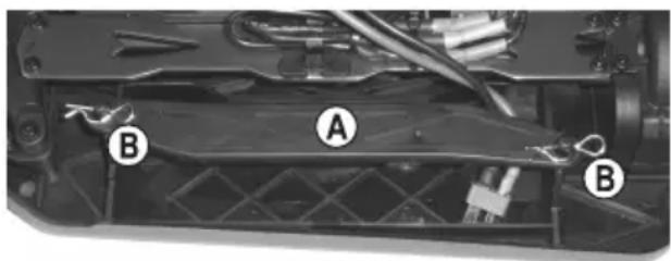
Remove the two clips (B) and lift the frame (A) off the battery holder.
Insert the vehicle battery. Ensure that the connection cable is behind the battery, otherwise the cable may impair the steering mechanism.
Replace the frame and secure it in place with the clips that you previously removed.
natural_image
Close-up of a mechanical component with labeled parts A and B, showing internal structure and wiring (no readable text or symbols beyond labels)e) Connecting the drive battery to the speed controller

Place the vehicle on a suitable support (or a start box) so that the wheels can move freely. This ensures that you will not lose control of the vehicle if the wheels move suddenly (e.g. if the throttle trim is not set correctly).
Do not reach into the motor or hold the wheels in place.
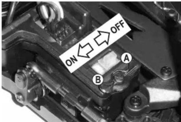
Switch off the speed controller (move the switch to the "OFF" position). The setup button (B) is located next to the on/off switch (A). This button can be used to program the speed controller (see section 10).
Switch on the remote control (see sections 9. b) and 9. c).
Connect the vehicle battery to the speed controller. Ensure that the battery is inserted in the correct polarity (red cable = positive/+, black cable = negative/-).
Do not use any force when connecting the battery to the speed controller. Ensure that cable cannot get caught in the motor/steering mechanism. If necessary, use cable ties to fix the cable in place.
text_image
ON OFF A Bf) Switching on the speed controller
Switch on the speed controller (move the switch to the "ON" position, see image in section 9. e). Wait for a few seconds (leave the throttle/brake lever in the neutral position). The speed controller will measure the battery voltage, which is indicated by the number of beeps.
• 2 beeps: 2-cell LiPo battery or 6-cell NiMH battery
• 3 beeps: 3-cell LiPo battery

Important!
The undervoltage detection feature works by detecting the battery voltage when the speed controller is switched on. (The undervoltage detection feature switches off the motor when the LiPo battery is empty to prevent the battery from overdischarging).
For this reason, ensure that you connect a fully charged battery to the speed controller.

For safety reasons, if the throttle/brake lever (or the throttle trim) is not in the neutral position when the speed controller is switched on, the LED on the speed controller will flash rapidly in red and the motor will not switch on. Release the throttle/brake lever on the remote control and check the trim setting for the throttle. If necessary, adjust the trim setting accordingly (see section 10. a).
Check that the throttle and steering functions are working correctly.
Refer to section 10. b) for instructions on how to program the speed controller.

Important!
When using a LiPo vehicle battery, remember to check whether undervoltage detection is enabled on the speed controller (normally 3.2 V/cell). If undervoltage detection is disabled, the LiPo may be permanently damaged due to overdischarge.
When using a NiMH battery, disable undervoltage detection or configure a lower voltage setting (see section 10. b).
The LED on the speed controller switches off when the throttle is in the neutral position and turns red when the forwards/reverse throttle is engaged. An additional green LED turns on when the vehicle is moving forwards at full throttle.
g) Attaching and fastening the car body
Now put the car body on the brackets and fasten it with the safety clips that were removed at the start.
h) Controlling the vehicle
Place the vehicle on the ground. Do not reach into the motor or hold the wheels.

The following images are for reference purposes only and do not necessarily correspond to the design of the remote control included with the product!
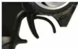
- Release the throttle/brake lever (move it to the neutral position). The vehicle should roll to a halt or stay stationary (if necessary, adjust the throttle trim on the remote control).
natural_image
Close-up of a black mechanical component with curved lines, possibly a tool or bracket (no visible text or symbols)- Slowly pull the throttle/brake lever towards the handle to make the vehicle move forwards.
natural_image
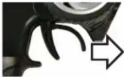
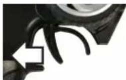
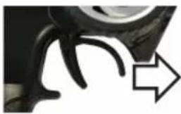
Close-up of a car tire with a white arrow pointing to the side (no visible text or symbols)- Move the throttle/brake lever away from the handle without a pause to make the vehicle move forwards and brake (the vehicle decelerates quickly rather than coming slowly to a standstill).
natural_image
Close-up of a mechanical component with a curved arrow pointing to it (no visible text or symbols)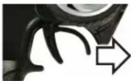
natural_image
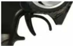
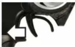
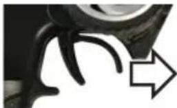
Close-up of a mechanical component with a curved arrow pointing right (no visible text or symbols)Move forwards, brake and reverse: Move the throttle/brake lever away from the handle without a pause (brake). If the vehicle is stationary, briefly move the throttle/brake lever to the neutral position (for approximately one second), and then move the throttle/brake lever away from the handle (the vehicle will start to reverse).

natural_image
Close-up of a mechanical component with a curved arrow pointing to it (no visible text or symbols)Move forwards
natural_image
Close-up of a black mechanical component with a curved arrow pointing to it (no text or symbols visible)Brake If the vehicle is stationary, wait for a moment (one second).
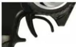
natural_image
Close-up of a black mechanical component with curved blades (no visible text or symbols)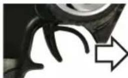
natural_image
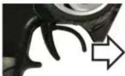
Close-up of a mechanical component with curved lines and an arrow indicating direction (no text or symbols)Reverse
Pulling the throttle/brake lever from forwards to reverse without a pause will activate the brakes (the vehicle will not reverse).
To switch from forward throttle to reverse, move the throttle/brake lever away from the handle into the neutral position (if the vehicle is moving forwards, the brake will be engaged). Then move the lever away from the handle again to make the vehicle reverse.

If the vehicle is moving forwards and you wish to make it reverse, the throttle/brake lever has to be moved away from the handle two times. This prevents the motor from being overloaded due to a sudden change from forwards to reverse throttle.
Move the throttle/brake lever on the remote control very carefully and drive slowly until you are familiar with how the vehicle responds to the remote control. Do not make rapid or sudden adjustments to the controls.
Never point the remote control antenna directly at the vehicle, as this considerably reduces the range. For best results, the remote control and vehicle antenna should be vertical and parallel to one another.
If the vehicle shows a tendency to move to one side, adjust the steering trim on the remote control accordingly.
When switching from forwards to reverse throttle, the throttle/brake lever must be placed in the neutral position for approximately one second (neutral position = release the lever and leave it in place). Pulling the throttle/brake lever from forwards to reverse without a pause will activate the brakes (the vehicle will not reverse).
Discontinue use immediately if the vehicle does not respond as expected, or if the vehicle stops responding to the remote control. If this occurs, the vehicle/remote control batteries may be nearly empty, or the vehicle may be too far from the remote control.
A damaged receiver antenna, interference on the wireless channel (e.g. from other devices, Bluetooth ^® or Wi-Fi) or poor reception/transmission conditions may cause the vehicle to respond incorrectly.
The receiver is powered by the speed controller/vehicle battery, therefore the vehicle may not move correctly when the vehicle battery is nearly empty (e.g. the steering servo may not work properly).
For example, the vehicle battery voltage may drop momentarily at full throttle, and the receiver may not receive the required voltage as a result. If this occurs, the vehicle will accelerate, but the steering servo will not respond correctly. Discontinue use immediately and use a new, fully charged vehicle battery.
If the vehicle battery is empty, wait for at least 5 - 10 minutes until the motor and speed controller have cooled down. You can then use the vehicle again with a fully charged battery.
i) Stopping the vehicle
To stop the vehicle, proceed as follows:
- Release the throttle/brake lever on the remote control so that it is in the neutral position, and then let the vehicle coast to a standstill.
- Wait until the vehicle has stopped, and then switch off the speed controller (move the switch to the "OFF" position).
Do not reach into the wheels or motor or move the throttle/brake lever on the remote control. Do not hold the vehicle by the wheels!

Warning!
The motor, speed controller and drive battery become very hot during use! Do not touch these parts immediately after use – burn hazard!
- Disconnect the vehicle battery from the speed controller. Remove the plug-in connectors.
- Switch off the remote control.
10. Programming the speed controller
a) Adjusting the neutral and full throttle setting
If the vehicle does not stay stationary when the throttle/brake lever is in the neutral position, you can adjust the throttle trim on the remote control.
If the trim is insufficient (or if the trim is almost in the end position), you can reset the trim accordingly.
Proceed as follows:
- Switch on the remote control and leave the throttle/brake lever in the neutral position (central position). Set the trim for forwards/reverse throttle to the central position.
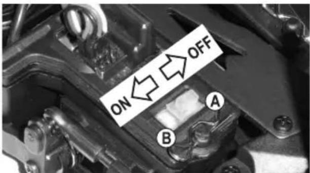
- Switch off the speed controller. Hold down the setup button (B) and turn on the speed controller (move the switch to the "ON" position).
- The LED on the speed controller will flash red and the motor will start to beep. Release the setup button.
text_image
ON OFF A BIf you do not release the setup button, programming mode will be enabled after a few seconds (see section 10. b). If this occurs, switch off the speed controller and repeat the above steps.

The beeps are produced by the brushless motor. Depending on the motor, the beeps may be very quiet. If so, pay attention to the status of the LED on the speed controller.
- Release the throttle/brake lever on the remote control so that it is in the neutral position.
- Press the setup button (B). The LED on the speed controller will flash once in green and the vehicle will beep. This indicates that the neutral setting has been saved.
- Move the throttle/brake lever to the full forwards throttle position (move it towards the handle and hold it in place).

Warning!
If you do not move the transmitter throttle/brake lever during the settings process, or you do not move it far enough, the vehicle may respond to even slight movements of the throttle lever or become uncontrollable. If this occurs, reprogram the throttle settings.
- Press the setup button (B). The LED on the speed controller will flash twice in green and the vehicle will beep twice. This indicates that the full throttle settings for the forwards throttle have been saved.
- Move the throttle/brake lever to full reverse throttle (push the lever away from the handle as far as it will go).
- Press the setup button (B). The LED on the speed controller will flash three times in green and the vehicle will beep three times. This indicates that the full throttle settings for the reverse throttle have been saved.
- Release the throttle/brake lever to return it to the neutral position.
- Wait for at least three seconds. The speed controller will automatically exit settings mode and apply the new settings.
b) Programming additional features

By default, the speed controller is preprogrammed with the optimal settings.
When using a LiPo vehicle battery, check the speed controller settings to confirm that undervoltage protection is enabled (normally 3.2 V/cell). If undervoltage detection is switched off, the LiPo battery may be permanently damaged due to overdischarge.
When using a NiMH battery, disable undervoltage detection or configure a lower voltage setting.
The setup button can be used to program the settings.
Proceed as follows:
- Switch on the remote control and leave the throttle/brake lever in the neutral position.
- Switch off the speed controller (move the switch to the "OFF" position).
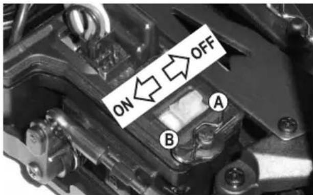
- Hold down the setup button (B) next to the on/off switch (A) and turn on the speed controller (move the switch to the "ON" position).
Keep holding down the setup button (B).
- The LED on the speed controller will flash red and the motor will beep (keep holding down the setup button).
- The LED will start to flash green after a few seconds (keep holding down the setup button).
text_image
ON OFF A BThe number of green flashes (1x...5x) indicates the selected setting.
1x flash and 1x beep: Forwards/reverse throttle or forwards throttle only
2x flashes and 2x beeps: Brake
3x flashes and 3x beeps: Undervoltage detection for the LiPo battery
4x flashes and 4x beeps: Startup mode
5x flashes and 5x beeps: Braking power

The beeps are produced by the brushless motor. Depending on the motor, the beeps may be very quiet. If so, pay attention to the status of the LED on the speed controller.
- Wait until the desired setting is indicated (e.g. undervoltage protection = 3x green LED flashes and 3x motor beeps), and then release the setup button (refer to the next page for a table with the various setting options).
- The LED will start to flash in red. The number of red flashes indicates the selected setting (e.g. 3.0 V/cell under-voltage protection = 4x red LED flashes + 4 motor beeps).
- Press the setup button to change the setting. The number of red LED flashes (and motor beeps) will change accordingly.
- Switch off the speed controller to exit settings mode and save the settings. The new settings will be automatically enabled when you switch the speed controller back on.
- Follow the above steps to change the other settings.
| Red LED flashes.... (+ Beep) | ||||||||||
| Function | Green LED flashes(+beep) | 1x short | 2x short | 3x short | 4x short | 1x long | 1x long, 1x short | 1x long, 2x short | 1x long, 3x short | |
| 1 | Drive function | 1x short | Forward/ Brake | Forward/ Brake/ Reverse | ||||||
| 2 | Motor brake | 2x short | 0% | 5% | 10% | 15% | 20% | 25% | 30% | 40% |
| 3 | Undervoltage protection | 3x short | Switched off | 2.6 V/cell | 2.8 V/cell | 3.0 V/cell | 3.2 V/cell | 3.4 V/cell | ||
| 4 | Starting mode | 4x short | Slow | Standard | Fast | Very fast | ||||
| 5 | Maximum braking strength | 5x short | 25% | 50% | 75% | 100% | ||||
The values marked in grey are the preset default values at the time this manual was published. The speed controller on your vehicle may have different default settings. To determine these settings, refer to the number of red LED flashes.
Overview of functions:
• Function #1, 1x green LED flash: Drive function
The speed controller can be switched between the two drive modes ("forwards/brake" and "forwards/brake/reverse").
In "forwards/brake" mode, the reverse function can be disabled. This is often required in racing competitions.
• Function #2, 2x green LED flashes: Brake function
The vehicle will slow down automatically when you release the throttle on the remote control or move the throttle/brake lever to the neutral position. The effect is the same as on a "real" car when you release the accelerator pedal without pushing the brake pedal.
The brake functions like a brake on a standard electric motor (a brushless electric motor does not feature strong magnets that slow down the rotor).
• Function #3, 3x green LED flashes: Undervoltage protection
When using a LiPo battery, always ensure that undervoltage protection is enabled (we recommend at least 3.2 V per cell). Failure to do so may cause the LiPo battery to overdischarge and result in permanent damage!
If you are using a 3-cell LiPo battery (approx. 12.6 V when fully charged) with a switch-off voltage of 3.2 V/cell and the speed controller measures a battery voltage of 9.6 V, the motor will be switched off to prevent the LiPo battery from overdischarging.
When using a NiMH battery, disable undervoltage protection or set the switch-off voltage to 2.6 V/cell.
If you insert a NiMH/NiCd battery with a voltage of less than 9 V, the speed controller will mistakenly detect the battery as a 2-cell LiPo battery when the speed controller is switched on. As a result, the speed controller will switch off when the battery voltage reaches 5.2 V (2 x 2.6 V).
If you insert a 6-cell NiMH/NiCd battery with a voltage higher than 9 V (e.g. batteries with a relatively high voltage), the speed controller will detect the battery as a 3-cell LiPo battery. As a result, the speed controller will switch off when the battery voltage reaches 7.8 V (3 x 2.6 V). In this case, undervoltage protection should be disabled to prevent the speed controller from switching off prematurely.
• Function #4, 4x green LED flashes: Startup mode
Depending on the setting, the vehicle starts with more or less power. A higher setting causes the motor to draw more current from the battery and therefore requires a high-grade battery.
A higher setting should only be used on unpaved surfaces, as paved surfaces may overload the motor (transmission, differentials).
• Function #5, 5x green LED flashes: Maximum brake force
The brake force delivered by the speed controller depends on the position of the brake lever on the remote control. The maximum brake force when the brake lever is fully engaged can be adjusted to 25%, 50%, 75% or 100%.
A higher setting (e.g. 100%) decreases the braking distance, but has a negative impact on the lifespan of the motor (especially the drive pinion and main gear).
c) Resetting the speed controller
Use this function to reset all configured settings to the factory defaults (see grey markings in the table in section 10. b).
Follow the steps below:
- Switch on the remote control and leave the throttle/brake lever in the neutral position.
- Switch on the speed controller (move the switch towards the setup button). The vehicle is now ready to use and the LEDs should be switched off.
- Hold down the setup button until the red and greed LEDs start to flash.
- Switch off the speed controller (move the switch to the "OFF" position, see image in section 10. a) or 10. b). All settings will be reset to the factory defaults (see table in section 10. b).
Refer to sections 10. a) and 10. b) for instructions on how to reprogram the speed controller.

Important!
When using a LiPo vehicle battery, check the speed controller settings to confirm that undervoltage protection is enabled (normally 3.2 V/cell). If undervoltage detection is switched off, the LiPo battery may be permanently damaged due to overdischarge.
When using a NiMH battery, disable undervoltage detection or configure a lower voltage setting (see section 10. b), function #3).
11. Adjustment options on the vehicle
a) Setting the camber
The camber is the inclination of the wheel level as viewed from the front (vertical).
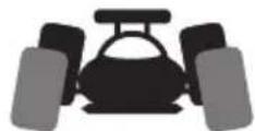
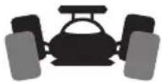
Negative camber Positive camber
(Upper wheel edge points inwards) (Upper wheel edge points outwards)
The alignment of the wheels is exaggerated in the two diagrams to show the difference between negative and positive camber. Obviously, such an extreme adjustment should not be made to the model vehicle!
- A negative camber on the front wheels increases the lateral forces on the tyres when cornering, the steering is more reactive, the steering forces are reduced. At the same time the wheel is pushed onto the axle leg in the direction of the axis. This offsets axial bearing clearance, the driving behaviour is smoother.
- A negative camber on the rear wheels reduces the tendency of the rear of the vehicle to swing when cornering.
- In contrast, setting a positive camber reduces the cornering force on the tyres and should generally not be used.
Adjust wheel camber on front or rear axle:
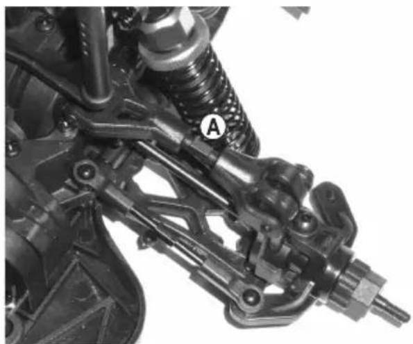
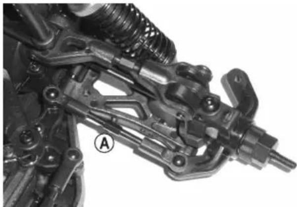
The wheel camber is adjusted by turning the screw (A) on the upper suspension arm.
A suitable open-ended spanner can be used to turn the screw (not included).
Because this screw has a left and right-hand thread, the suspension arm does not have to be disassembled to set the wheel camber.
natural_image
Mechanical assembly diagram showing suspension components and a labeled section (A), no readable text or symbols present.b) Setting the alignment
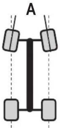
Wheel alignment (toe-in = figure "a", toe-out = figure "b") describes the alignment of the wheel with regard to the driving direction.
During driving the tyres are pushed apart at the front because of the rolling friction and are therefore no longer exactly parallel to the direction of travel.
To balance this out, the tyres of the stationary vehicle can be adjusted in a way so that they point slightly towards the inside. This toe-in improves the lateral cornering of the tire and therefore leads to a more direct response to the steering.
If a milder response to steering is desired, this can be achieved accordingly by adjusting a toe-out, i.e. the wheels of the stationary vehicle point outward.
natural_image
Simple diagram of a vertical structure with four rectangular blocks and dashed vertical lines, labeled 'A' at top (no text or symbols within the diagram itself)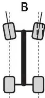
natural_image
Simple diagram of a vertical structure with four rectangular blocks connected by lines, labeled 'B' (no text or symbols within the diagram itself)
A trail angle of more than 3^ toe-in (A) or toe-out (B) leads to handling problems and reduces the speed. It also increases tyre wear.
The figure above shows a heavily over-emphasised setting. It is only used to show the difference between toe-in and toe-out. If a similar setting is used for the vehicle, it will be very difficult to control!
Setting the front axle alignment:
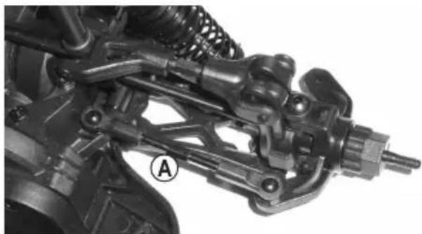
For the front axle, the alignment can be set by turning the steering knuckle arm (A). As this has a left and right hand-thread, it does not have to be disassembled to be adjusted.
Turn both steering knuckle arms the same amount (left and right front wheel). Otherwise, the trim on the transmitter has to be adjusted (or possibly the steering servo control by adjusting the servo rod).
natural_image
Mechanical assembly diagram showing internal components and a labeled section (A), no readable text or symbols present.Setting the rear axle alignment:
For the rear axle, the alignment can be set by turning the steering knuckle arm (A). As this has a left and right hand-thread, it does not have to be disassembled to be adjusted.
Always turn both knuckle arms equally (left and right rear wheel).
natural_image
Mechanical assembly diagram showing a vehicle suspension system with labeled component A (no text or symbols beyond label)c) Adjusting the shock absorbers
natural_image
Mechanical assembly diagram showing a spring-loaded component with labeled parts A and B (no text or symbols beyond labels)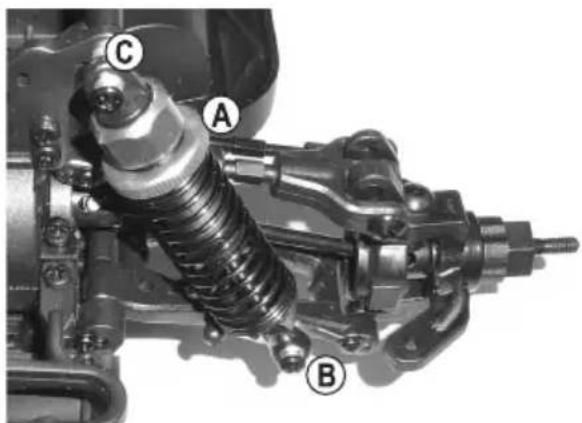
text_image
A B CFront axis Rear axis
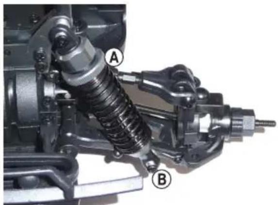
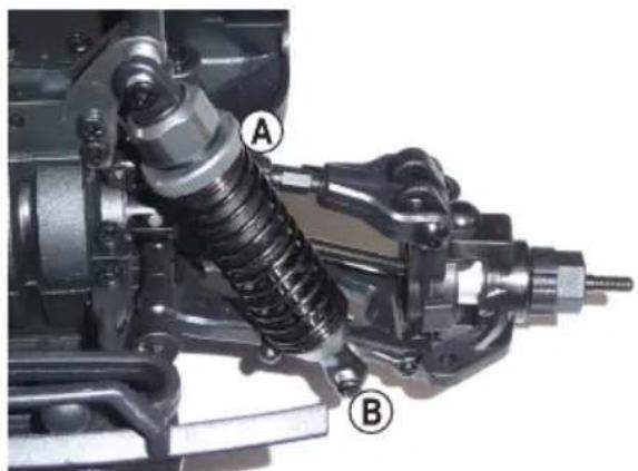
At the upper end of the shock absorber, the spring tension can be adjusted by turning the knurl (A).
The shock absorbers of the vehicle can be mounted in different positions on the lower wishbone (B) or on the top of the damper bridge (C, only possible on the rear axle). However, the manufacturer has already selected an optimal position here, therefore a change should only be carried out by professional drivers.
Always set the shock absorbers on one axle evenly (at the left and right wheels of the front or rear axle). Otherwise, driving behaviour will be negatively affected.
Professional drivers can also use springs with a different level of firmness or fill the shock absorbers with a shock oil of a different viscosity.
Just as with a "real" car, the shock absorbers (and the rubber seals in the shock absorbers) are a wear part on a model car. If oil is leaking from the shock absorbers (e.g. suspension arm is heavily oiled, dripping), the gaskets or shock absorbers must be replaced.
12. Cleaning and care
a) General information
Before cleaning or maintenance, the speed controller must be turned off and the rechargeable drive battery must be completely disconnected from the speed controller. Then switch off the transmitter off. If you drive the vehicle beforehand, first let all parts (e.g. motor, drive control, etc.) cool down completely.
Clean the whole vehicle of dust and dirt after driving, use e.g. a long-haired clean brush and a vacuum cleaner. Compressed air aerosols can also be helpful.
Do not use cleaning aerosols or conventional household cleaners. This may damage the electronics and lead to discolouration on the plastic parts or the body.
Never wash the vehicle using a high-pressure cleaner.
A soft cloth, slightly dampened, can be used to wipe the car body. Do not rub too firmly otherwise you will scratch the vehicle.
b) Before and after each trip
Motor vibrations and shocks during driving can loosen parts and screw fittings.
Therefore, check the following before and after each trip:
- That all wheel nuts and all screw fittings on the vehicle are tight
- The attachment of the speed controller, on/off switch, receiver
- The adhesion of the tyres to the wheel rims and tyre condition
- The attachment of all cables (this cannot be done in the movable parts of the vehicle)
- The functioning of the fan on the speed controller
In addition, always check the vehicle for damage before and after each use. If you notice any damage, the vehicle must not be used any more and must be taken out of operation.
Only use original spare parts when replacing worn vehicle parts (e.g. tyres) or defective vehicle parts (e.g. a broken suspension arm).
c) Changing a tyre
The tyres are fixed on the wheel rim and cannot be removed. Therefore, if the tyre is worn, the entire wheel has to be replaced.
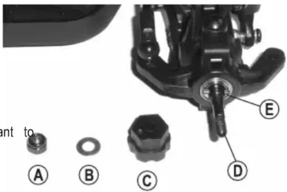
Loosen the wheel nut (A) and remove the washer (B). Then slide the wheel off the wheel axle (D).
The wheel tappet nut (C) may be stuck in the wheel rim when you slide off the rear wheel in the rim or it may come away from the front wheel (D). Make sure that the tappet pin (E) does not fall off and get lost.
If the wheel is subsequently re-fitted, it is important check that the tappet pin (E) is inserted exactly in the centre of the wheel axle (D) and is positioned in the corresponding notch on the wheel tappet nut (C).
If the tappet pin (E) is missing, no torque can be transferred from the motor to the wheel. The wheel turns freely.
text_image
ant to A B C E DThe new wheel is then fitted so that the internal hex socket on the inside of the wheel rim fits precisely over the wheel tappet nut (C).
Place the washer (B) on the wheel axle (D) and screw the wheel tight with the wheel nut (A).
Make sure that the wheel nut (A) is correctly aligned when tightening it. The wheel nut is a so-called self-locking nut; on one side of the self-locking nut, there is a plastic insert. This must point outwards when the wheel nut is tightened.
Do not apply any force when tightening the wheel nut, because then the wheel will be difficult to turn and this can damage the drive.
13. Disposal
a) Product

Electronic devices are recyclable waste and must not be placed in household waste. Always dispose of the product according to the relevant statutory regulations.

ve any inserted batteries and dispose of them separately from the product.
b) Batteries
As the end user, you are required by law to return all used batteries (Battery Directive). They must not be disposed of in household waste.

Batteries containing harmful chemicals are labelled with this symbol to indicate that disposal in household waste is forbidden. The designations for the heavy metals involved are: Cd = Cadmium, Hg = Mercury, Pb = Lead (indicated on the battery, e.g. below the trash icon on the left).
Used batteries can be returned free of charge to local collection points, our stores or any retailers selling batteries.
You thus fulfil your statutory obligations and contribute to the protection of the environment.
14. Declaration of Conformity (DOC)
Conrad Electronic SE, Klaus-Conrad-Straße 1, D-92240 Hirschau, hereby declares that this product conforms to the 2014/53/EU directive.

Click on the following link to read the full text of the EU declaration of conformity:
www.conrad.com/downloads
Select a language by clicking on the corresponding flag symbol, and then enter the product order number in the search box. The EU Declaration of Conformity is available for download in PDF format.
15. Troubleshooting
Even though the model and the remote control system were built with the latest available technology, there can still be malfunctions or faults. This is why we would like to show you how to correct possible faults. Also observe the enclosed operating instructions for the remote control system.
The model does not respond or does not respond correctly.
- In the case of 2.4 GHz remote control systems, the receiver must be connected to the remote control. This process is known as "pairing". The manufacturer pairs the remote control with the receiver before the vehicle is shipped. However, you can also pair the remote control yourself. Refer to the remote control operating instructions for details.
- Is the vehicle battery or the remote control batteries empty? If so, replace the vehicle battery or remote control batteries.
- Did you switch on the remote control before switching on the speed controller? For safety reasons, the speed controller does not function if this is done in the reverse order.
- Is the vehicle battery connected to the speed controller? Check the connection to see if it is dirty or rusted.
- Is the vehicle too far away? The range should be at least 50 m when the vehicle battery and the remote control batteries are full. However, this can be reduced by the ambient conditions, such as interference on the transmission frequency or proximity to other transmitters (including Wi-Fi/Bluetooth® devices that use a transmission frequency of 2.4 GHz), metal objects and buildings.
The position of the remote control and receiver aerials relative to one other also has a significant impact on the range. For best results, the remote control and receiver aerial should be vertical (i.e. parallel to each other). Pointing the remote control aerial at the vehicle significantly reduces the range.
- Check the connectors on the speed controller and steering servo in the receiver. If the connectors have been inserted in the wrong orientation (rotated by 180^ ), the speed controller and steering servo will not work.
If the connectors for the speed controller and steering servo are connected the wrong way round, the throttle/brake servo will control the steering servo (and vice versa).
- For safety reasons, if the throttle/brake lever (or the throttle trim) is not in the neutral position when the speed controller is switched on, the LED on the speed controller will flash rapidly in red and the motor will not switch on. Release the throttle/brake lever on the remote control and check the trim setting for the throttle. If necessary, adjust the trim setting accordingly (see section 10. a).
The vehicle doesn't stop when the throttle/brake lever is released.
- Correct the throttle trim on the remote control (set the neutral position).
- If the trim is insufficient, reset the neutral and full throttle positions (see section 10. a).
The vehicle travels slowly or the steering servo does not respond properly to remote control commands; the range between the remote control and the vehicle is very short.
• The vehicle battery is nearly empty.
The receiver and the steering servo are powered by the BEC in the speed controller. As a result, the receiver will not function properly when the battery is nearly empty. Replace the vehicle battery with a fully charged battery (before changing the battery, wait for at least 5–10 minutes for the motor and speed controller to cool down).
- Check the batteries in the remote control.
The vehicle does not travel in a straight line
- Set the steering trim on the remote control.
- Check the steering linkage, servo arm, servo saver and screw connection.
- Has the vehicle had an accident? If so, check the vehicle for any defective or broken parts and replace them if necessary.
The vehicle moves in the opposite direction to the steering wheel on the remote control
- Enable the steering reverse function on the remote control.
The vehicle responds in the opposite way to the throttle/brake lever on the remote control
• Usually, the vehicle should move forwards when the throttle/brake lever on the remote control is pulled towards the handle.
If this is not the case, enable the reverse throttle on the remote control.
- If the motor was disconnected from the speed controller, swap the positions of two of the three motor cables.
The vehicle does not steer properly or the steering angle is too low
- If the transmitter has a dual rate setting, check that it is working correctly (refer to the remote control operating instructions for details). If the dual rate setting is too low, the steering servo will not respond.
- Check the steering mechanism for loose parts (e.g. check whether the servo arm is attached correctly to the servo).
The drive battery heats up during charging and when driving the vehicle
- This is normal.
16. Technical data
a) Vehicle
Scale....1:10
Suitable drive battery....3-cell LiPo drive battery (nominal voltage 11.1 V)
Drive Brushless electric motor (2100 KV)
Four wheel drive via cardan shaft
Differential in front and rear axle
Chassis....Independent suspension, front/rear
Oil pressure shock absorbers with coil springs, adjustable
Adjustable front/rear wheel alignment
Adjustable front/rear wheel camber
Dimensions (L x W x H)....440 x 290 x 178 mm
Tyre dimensions (W x ∅)....60 x 125 mm
Wheel base....290 mm
Ground clearance....40 mm
Weight ....approx. 2068 g (without battery)
→ The product dimensions and weight may vary slightly.
b) Remote control system
→ Follow the separately included operating instructions for the remote control system.
c) LiPo charger
→ Follow the separately included operating instructions for the LiPo charger.
d) LiPo battery
Type....LiPo, 3 cells (nominal voltage 11.1 V); with T-connector
Capacity....3200 mAh
Discharge rate 20C
Page
France (email) : technique@conrad-france.fr
natural_image
Close-up of a mechanical component with labeled parts A and B, showing internal structure and wiring (no readable text or symbols beyond labels)natural_image
Close-up of a black mechanical component with curved blades (no visible text or symbols)natural_image
Close-up of a car tire with a curved handle and arrow pointing to it (no visible text or symbols)natural_image
Close-up of a mechanical component with a curved black spring-like structure and a white arrow pointing to it (no text or symbols visible)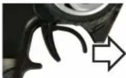
natural_image
Close-up of a mechanical component with a curved handle and an arrow pointing to it (no text or symbols visible)natural_image
Close-up of a car wheel and gear mechanism with a white arrow pointing to the gear (no text or symbols visible)Marche avant
natural_image
Close-up of a car wheel with a curved handle and an arrow pointing to it (no text or symbols visible)natural_image
Close-up of a black mechanical component with curved arms (no visible text or symbols)natural_image
Close-up of a car wheel handle with an arrow pointing to it (no text or symbols visible)Marche arrière
natural_image
Mechanical assembly diagram showing springs, gears, and linkages (no text or symbols)natural_image
Diagram of a vehicle suspension system with four wheels and a central vertical shaft, labeled 'A' (no text or symbols on the diagram itself)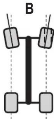
natural_image
Pure diagram of a vertical structure with four rectangular blocks and dashed lines, no text or symbols present.
natural_image
Mechanical assembly diagram showing internal components and springs (no text or symbols)natural_image
Mechanical assembly diagram showing a vehicle suspension system with labeled component A (no text or symbols beyond label)natural_image
Mechanical assembly diagram showing a spring-loaded component with labeled parts A and B (no text or symbols beyond labels)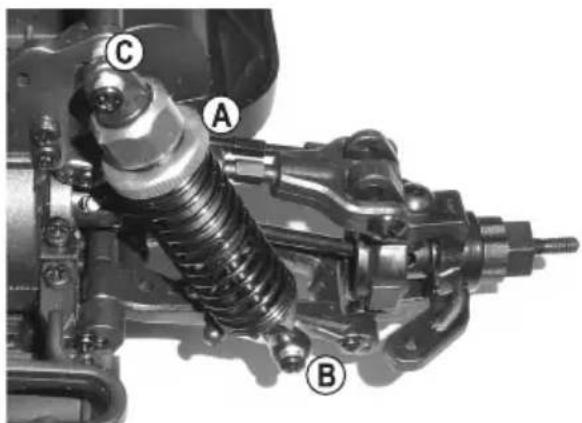
text_image
Technical diagram of a mechanical assembly with labeled parts A, B, and Ctext_image
Technical diagram of a mechanical assembly with labeled parts A, B, C, D, and Ewww.conrad.com/downloads
Dimensions (L x l x H)....440 x 290 x 178 mm
Dimension des pneus (l x ∅)....60 x 125 mm
Empattement 290 mm
natural_image
Close-up of a mechanical component with labeled parts A and B, showing internal structure and wiring (no readable text or symbols beyond labels)natural_image
Close-up of a black mechanical component with curved arms (no visible text or symbols)natural_image
Close-up of a car tire with a curved tire and arrow pointing to it (no visible text or symbols)natural_image
Close-up of a mechanical component with a white arrow pointing to a curved part (no visible text or symbols)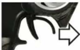
natural_image
Close-up of a black mechanical component with a curved arrow pointing to it (no text or symbols visible)natural_image
Close-up of a car tire with a curved tire and arrow indicating direction (no text or symbols)Vooruitrijden
natural_image
Close-up of a mechanical component with a curved arrow pointing to it (no visible text or symbols)natural_image
Close-up of a mechanical component with curved and straight elements (no visible text or symbols)even wachten
(1 seconde)
natural_image
Close-up of a car wheel with a black arrow pointing to it, no visible text or symbolsAchteruitrijden
natural_image
Close-up of a mechanical assembly with springs and brackets, no visible text or symbolsb) Spoor instellen
natural_image
Simple diagram of a vertical structure with four wheels and a central black bar, labeled 'A' at top (no text or symbols on the diagram itself)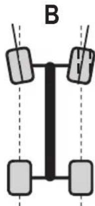
natural_image
Pure diagram of a vertical structure with four rectangular blocks and dashed lines, no text or symbols present.
natural_image
Mechanical assembly diagram showing a mechanical component with springs and shafts (no text or symbols visible)natural_image
Mechanical assembly diagram showing a vehicle's suspension system with labeled component A (no text or symbols beyond label)c) Schokdempers instellen
natural_image
Mechanical assembly diagram showing a spring-loaded component with labeled parts A and B (no text or symbols beyond labels)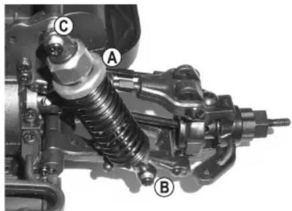
text_image
Technical diagram of a mechanical assembly with labeled parts A, B, and CVooras Achteras
text_image
Technical diagram of a mechanical assembly with labeled parts A, B, C, D, and Ewww.conrad.com/downloads
This is a publication by Conrad Electronic SE, Klaus-Conrad-Str. 1, D-92240 Hirschau (www.conrad.com).
All rights including translation reserved. Reproduction by any method, e.g. photocopy, microfilming, or the capture in electronic data processing systems require the prior written approval by the editor. Reprinting, also in part, is prohibited. This publication represents the technical status at the time of printing.
Copyright 2020 by Conrad Electronic SE.
Copyright 2020 by Conrad Electronic SE.
Copyright 2020 by Conrad Electronic SE.