New1 - Remote control toy Reely - Free user manual and instructions
Find the device manual for free New1 Reely in PDF.


User questions about New1 Reely
0 question about this device. Answer the ones you know or ask your own.
Ask a new question about this device
Download the instructions for your Remote control toy in PDF format for free! Find your manual New1 - Reely and take your electronic device back in hand. On this page are published all the documents necessary for the use of your device. New1 by Reely.
USER MANUAL New1 Reely
GB Operating Instructions
1:10 Electric Monster truck "NEW1" 4WD kit Item No. 1783397 Page 26 - 49
© Notice d'emploi
www.business.conrad.at
text_image
Technical diagram of a mechanical component with numbered parts labeled 1, 2, and 3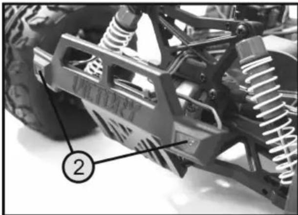
natural_image
Close-up of a heavy-duty toy vehicle chassis with visible springs and structural components (no text or symbols)Bild 1
natural_image
Two identical illustrations of a toy car with large tires, labeled A and B, shown side by side without any text or symbols.Bild 2
text_image
Technical diagram of a vehicle suspension system with labeled components 1 and 2Bild 3
text_image
Technical diagram of a vehicle suspension system with numbered components labeled 1, 2, and 3.Bild 4
natural_image
Two identical cartoon-style cars labeled A and B, shown from top-down perspective with no text or symbols on the vehicles themselves.Bild 5
text_image
Technical diagram of a vehicle suspension system with labeled components 1 and 2Bild 6
text_image
Labeled mechanical assembly diagram showing a spring-loaded vehicle suspension system with numbered componentsBild 7
text_image
Technical diagram of a mechanical assembly with numbered components labeled 1, 2, 3, and 4Bild 8
text_image
Technical diagram of a mechanical assembly with numbered components labeled 5, 6, and 7Bild 9

Achtung, wichtig!
- Introduction......27
- Explanation of symbols....27
- Intended use....28
- Delivery content....28
- Required accessories 29
- Safety instructions ....30
a) General information....30
b) Assembly 31
c) Operation....31
- Battery information....33
- Assembling the model vehicle 34
- Completing the model vehicle....40
a) Installing the lighting kit 40
b) Setting the remote control and speed controller....41
c) Decorating the chassis 41
- Setting up the chassis....42
a) Configuring the camber 42
b) Configuring the tyre track 43
c) Adjusting the shock absorbers 44
- Getting started with the model vehicle....45
- Maintenance and cleaning....45
a) General information....45
b) Before and after each use 46
c) Adjusting the backlash....46
d) Adjusting the slip clutch 47
- Disposal....48
a) Product 48
b) (Rechargeable) batteries 48
- Technical data....49
1. Introduction
Dear customer,
Thank you for purchasing this product.
This product complies with statutory national and European regulations.
To ensure that the product remains in this state and to guarantee safe operation, always follow the instructions in this manual.

These operating instructions are part of this product. They contain important information on setting up and using the product. Do not give this product to a third party without the operating instructions. Therefore, retain these operating instructions for reference!
All company and product names included herein are trademarks of their respective owners. All rights reserved.
If there are any technical questions, please contact:
International: www.conrad.com/contact
United Kingdom: www.conrad-electronic.co.uk/contact
2. Explanation of symbols

The symbol with an exclamation mark in a triangle is used to highlight important information in these operating instructions. Always read this information carefully.
The arrow symbol indicates special information and tips on how to use the product.
3. Intended use
The monster truck is an electric-powered model vehicle that is wirelessly controlled using a suitable radio remote control unit (not included). For operation of the model vehicle, various accessories are required that are not included and must be ordered separately (see chapter 5).
The model vehicle is intended exclusively for private use in the model making sector with the associated operation times.
The model is intended for outdoor use only.
This product is not suitable for children under 14 years of age.

Always follow the safety information in these operating instructions. It contains important information on how to use the product safely.
You are responsible for the safe operation of this model!
4. Delivery content
- Vehicle kit
• Lighting kit with two white LEDs and two red LEDs
• Assembly instructions - Operating instructions
Up-to-date operating instructions
Download the up-to-date operating instructions at www.conrad.com/downloads or scan the QR code shown. Follow the instructions on the website.

5. Required accessories
The monster truck is delivered as a kit and must be assembled before first use. For this purpose, the kit comes with separate assembly instructions with drawings of the different assembly stages. These instructions contain important tips and recommendations for proper assembly of the model.

Important!
individual parts found in the respective assembly drawings are packed separately. Only open the plastic bags to assemble the parts.
For assembly, you can use standard tools such as a screwdriver, pliers or an Hex key. However, you should always use suitable screwdrivers to avoid damaging the screw heads during assembly.

Practical tips:
A model vehicle stand is an effective tool for assembly of the vehicle. In addition to easy assembly, the stand can be used later for trial runs of the drive mechanism or for maintenance purposes.
For operation of the model vehicle, the following accessories are required that are not included and must be ordered separately:
• Remote control unit (transmitter and receiver)
- Steering servo
- Speed controller
- Drive motor
• Drive rechargeable battery (racing pack)
- Batteries or rechargeable batteries for the remote control unit (for type and required quantity, see operating instructions for the remote control unit)
• Suitable charger for transmitter or drive rechargeable batteries
For best results, we also recommend the following components:
- Spare tyres (in order to quickly change worn/damaged tyres)
• Compressed air spray (for cleaning) - Thread-locking fluid (to fix loose screw connections)
- Carry bag

Damage caused due to failure to observe these instructions will void the warranty. We shall not be liable for any consequential damage.
We shall not be liable for damage to property or personal injury caused by incorrect handling or failure to observe the safety information! Such cases will void the warranty/guarantee.
The guarantee and warranty also exclude normal wear and tear during operation (such as worn tyres or worn gears) and accident damage (such as broken chassis parts or suspension arms).
Dear customer,
These safety instructions are designed to ensure the safe operation of the product and your personal safety. Read this section very carefully before using the product.
a) General information
Caution, safety hazard!
This model has the potential to cause damage to property and/or individuals. Ensure that you are sufficiently insured, e.g. by taking out private liability insurance.
If you already have a policy, check with your insurance company that use of this model is covered by the policy.
- The unauthorised conversion and/or modification of the product is prohibited for safety and approval reasons.
• This product is not a toy and is not suitable for children under 14 years of age.
• The product must not become damp or wet. - Do not leave packaging material carelessly lying around, because it could become a dangerous plaything for children.
- If you have any questions that are not answered by these operating instructions, contact us (see section 1 for contact information) or an experienced technician.
- Operation and handling of remote controlled model cars must be learned! If you have never steered such a vehicle, drive especially carefully and get used to the car's responses to the remote control commands first. Be patient!
- Do not take any risks when using the product! Always use the model responsibly, otherwise you may endanger yourself and your surroundings.
- Occasional maintenance work and repairs are required to ensure safe use. For example, the tyres may become worn, or some parts may be damaged due to driver error.
• Only use genuine spare parts for maintenance and repair work.

b) Assembly
- During vehicle assembly, there is a risk of injury due to sharp edges, pointed parts and improper handling of tools.
- Improper assembly may result in damage to vehicle parts and poor performance. So be very careful when assembling.
- To assemble the vehicle, use only a sufficiently large, flat, and stable surface. Protect the surface of a work table from scratches by using a suitably thick underlay.
- Do not use force when assembling parts. Do not overtighten the screws! However, make sure that screws, nuts, etc. are tightened correctly.
• For assembly, use suitable tools in excellent condition.
• Take your time! - If you have never assembled such a vehicle before, seek guidance from a model maker who has the required knowledge. A few helpful tips and assistance from a professional can easily solve many problems, especially at the beginning of a “model making career”.
c) Operation
- Before each use, make sure that no other models are operating on the same frequency within the range of the remote control when operating the model with a 27 or 40 MHz remote control unit. Control of the remote controlled vehicle will be lost! Always use different frequencies for each model.
- With every operation, the settings of the trim regulator for forward/reverse drive as well as those for steering must be checked, and if necessary, modified.
- For this reason, the wheels of the vehicle must not be put on the ground during setup (switching on the remote control and the vehicle). Place the vehicle on a suitable surface so that the wheels can turn freely (do not touch the drive!).
- Then adjust the trim accordingly so that when the lever for the forward/reverse drive (neutral position) is fully released, the motor stops rotating or the steering is straight (straight drive can accurately be adjusted later while operating the vehicle).
- During setup, always switch on the remote control (transmitter) first. Only then can the rechargeable battery pack of the vehicle be connected with the cruise control/receiver and the model be switched on. Otherwise there may be unexpected responses by the cruise control/receiver and therefore the electric model!
- Improper use can cause serious injury and damage to property! Only use the vehicle when it is within your sight. Do not use the vehicle at night.
- Only use the vehicle when you are fully alert and able to respond. As is the case when driving a real vehicle, fatigue, alcohol or medications can affect your ability to respond.
- Please note that this model car should not be driven on public roads or streets. Only operate it on private sites or places which are specifically designated for remote-controlled models.
• Do not drive the vehicle towards people or animals.

- Do not drive the vehicle in the rain or through wet grass, water, mud or snow. The model is not waterproof or watertight.
- Also avoid driving at very low outdoor temperatures. Cold temperatures can cause the plastic on the chassis to lose its elasticity. In this case, even small accidents may damage the model.
- Do not use the vehicle during thunderstorms, under high-voltage power lines or next to radio masts.
- Do not take any risks when using the product! Always use the model responsibly, otherwise you may endanger yourself and your surroundings.
- Always leave the remote control turned on when the model is in use. To stop the vehicle, always turn the vehicle off first and then separated the rechargeable battery pack from the cruise control/receiver, only after that can the remote control be turned off.
• Before using the model, check whether it responds properly to the remote control commands. - In the case of weak batteries (or rechargeable batteries) in the remote control, the range decreases. When the drive rechargeable battery is weak, the vehicle gets slower or no longer responds correctly to the remote control.
If this is the case, stop operation immediately. Then replace the batteries/rechargeable batteries in the remote control with new ones, or recharge the rechargeable batteries in the vehicle or the remote control. - The motor and drive as well as the cruise control and the rechargeable battery pack of the car get hot during operation. Before replacing or recharging the rechargeable batteries, always wait at least 5 to 10 minutes for all parts to cool down.
Do not touch the motor, the speed controller or the rechargeable battery until they have cooled down. Risk of burn.
7. Battery information

Batteries present numerous safety hazards.
Therefore, always observe the following general information and safety instructions when handling non-rechargeable and rechargeable batteries.
- Keep batteries out of the reach of children.
- Do not leave batteries lying around, as they present a choking hazard for children and pets. Seek immediate medical advice if a battery is swallowed.
- Batteries/rechargeable batteries must never be short-circuited, taken apart or thrown into fire. This may cause an explosion!
- When handling leaking or damaged batteries, always use suitable protective gloves to avoid burning your skin.
- Do not attempt to recharge disposable, non-rechargeable batteries. This may cause a fire or explosion! Only charge rechargeable batteries which are intended for this purpose (1.2 V); use suitable battery chargers. Non-rechargeable batteries (1.5 V) are designed to be used once and must be disposed of properly when they are empty.
- Pay attention to the correct polarity when inserting batteries (observe plus/+ and minus/-). Incorrect polarity will not only damage the transmitter and batteries. It may also cause a fire or explosion.
- If you do not plan to use the model for an extended period (e.g. during storage), remove the batteries from the remote control to prevent them from leaking and causing damage. Disconnect the vehicle battery from the speed controller.
- Rechargeable batteries should be charged at least once every 3 months to prevent damage due to deep discharge.
• Always replace the entire set of batteries or rechargeable batteries. Do not mix full batteries with half-full ones. Always use batteries of the same type and from the same manufacturer. - Never mix non-rechargeable batteries with rechargeable batteries. The remote control can be powered with disposable or rechargeable batteries.
- Never charge the drive rechargeable battery immediately after use. Always leave the drive rechargeable battery to cool down until it has reached room or ambient temperature again.
- Only charge intact and undamaged drive rechargeable batteries. Do not charge the rechargeable battery if the external insulation of the rechargeable battery is damaged, or if the rechargeable battery is deformed or swollen. This may cause a fire or explosion!
- Never damage the outer shell of the drive rechargeable battery, do not cut the foil wrapping, and do not pierce the drive rechargeable battery with sharp objects. This may cause a fire or explosion!
• Never recharge the rechargeable battery unattended. - Disconnect the drive rechargeable battery from the charging cable when it is fully charged.
8. Assembling the model vehicle
Required tools:
• Phillips-head screwdriver of suitable size
• 1.5 mm, 2 mm, 2.5 mm, 5 mm hex keys
- Needle-nose pliers
- Combination pliers
• 5.5 mm and 7 mm socket wrenches
- Scissors
- Tweezers
- Table mat
Required accessories (see also chapter 5):
For assembly and completion of the model vehicle, the following accessories are required that are not included in the delivery scope of the model:
• Remote control unit with transmitter and receiver (at least 2 channels)
• 40 Ncm steering servo
• Electric motor size 550
• 40 A speed controller
• Drive rechargeable battery with suitable charger
For a brush electric motor version, we recommend that you use the following components:
• RC entry-level kit, Conrad item no. 209469
• "Turbo" electric motor, Conrad item no. 1600331
- "Brushed" speed controller, Conrad item no. 1399921
Before you start assembling the model, check the scope of delivery of individual parts. The package must contain a total of 18 sealed plastic bags marked with letters A - Q. Some larger bags include other small bags marked accordingly with letters and numbers, e.g. A - 1, A - 2, A - 3, etc. For a better overview, some small bags include other smaller bags with separately packed components. These smaller bags are marked as follows: A - 3 - 1, A - 3 - 2, etc.

Important!
tion to these operating instructions, refer to the separate assembly instructions. The procedure for proper assembly of the model vehicle is shown in 37 clear drawings. These assembly instructions also contain additional information and practical tips for each assembly stage.
A sketch of the required screws with the respective dimensions can always be found at the top left of the assembly instructions. The number in brackets indicates the quantity of screws. A designation of the parts bag that is required for each assembly stage can be found at the top right of the drawings. To avoid confusion, only open the parts bag that is needed for the assembly stage.
Do not go to the next assembly stage and do not open another parts bag until you have assembled all parts from the current assembly stage.
Assembly drawing 1:
Assemble the plastic parts according to the drawing shown in drawing 1. If you have any questions regarding assembly, you can check the following sketches for the correct positions of the components.
Assembly drawing 2:
The countersunk screws must be flush with the underside of the aluminium plate and must not protrude below.
Assembly drawing 3:
First mount a lock washer on each steel pin. Use a pair of small pliers. Then slide the two pins into the suspension arms according to the drawing and mount the second lock washer.
Assembly drawing 4:
When assembling the lower suspension arm, pay attention to the correct mounting position. The angled sides of the two suspension arms must be aligned backwards with the rear bumper.
Assembly drawing 5:
The individual parts of the slip clutch shown in drawing 5 are just for a better overview. The slip clutch (A) is delivered fully assembled and preset.
Assembly drawing 6:
Check the adjustment of the slip clutch before installation. The distance between the adjusting screw and the pressure plate must be 7 mm.

Important!
The M3 x 3 grub screw must grip the flattened part of the shaft.
Assembly drawing 7:
Drawing 7 shows individual parts of the pre-assembled differential.
Assembly drawing 8:
The backlash can be adjusted using the thin shim rings (B). The kit includes several washers. Choose the combination where the gears are meshed without backlash or jamming. Apply some ball bearing grease to the gears before closing the differential casing.
Assembly drawing 9:
Make sure that the screws, which are mounted from below, have a countersunk head and are therefore flush with the chassis plate.
Assembly drawing 10:
Among the screws, which are screwed into the chassis from below, ten screws have a countersunk head and one screw has a round head. Make sure that the round-head screw is mounted in the right place.

The screws contained in the C - 3 bag are used for the assembly of the cardan shaft cover. The cover will be assembled at a later assembly stage.
Assembly drawing 11:
Tighten the two grub screws shown in drawing 11 only as far as necessary to secure the chassis mount. Later, when adjusting the chassis, adjust the height of the mount and tighten it securely. The two upper suspension arms (C) are already assembled.
Assembly drawing 12:
First, use the two short screws (M3 x 10) to attach the shock absorber bridge to the differential casing. But do not tighten the screws yet. Before mounting the upper suspension arms, compare the length of the two suspension arms. The suspension arms must be exactly the same length so as to ensure the same camber on both rear wheels. When installing the suspension arms, tighten all screws securely.
Assembly drawing 13:
When assembling the steering knuckles, make sure that there are two of them: right (R) and left (L). This must be considered during assembly at the next assembly stage.
Assembly drawing 14:
First securely tighten the steering knuckle at the bottom and then mount the cardan shaft. Then the upper fixing screw can be mounted.
Assembly drawings 15 and 16:
The two figures show the schematic layout of the shock absorbers. The shock absorbers are delivered completely assembled.
Assembly drawing 17:
When installing the shock absorbers, make sure that the spacer sleeve (D) is mounted between the shock absorber and the shock absorber bridge.
Assembly drawing 18:
Drawing 18 shows the assembly of the cardan shaft cover. Make sure that the countersunk screw is mounted at the right rear.
Assembly drawing 19:
Do not overtighten the three M3 x 6 screws to prevent them from damaging the plastic surface.
Assembly drawing 20:
The aluminium plate must be assembled so that the countersunk screws are flush and do not protrude below.
Assembly drawing 21:
Drawing 21 shows the assembly of the front suspension arms. The kit comes with a 5 mm hex key that is used for tightening the plastic inserts (E). First, securely tighten the inserts with care. Then loosen the inserts until the pivot ball screws (F) can move easily; there should be no play in the bearing in doing so.

Important!
The suspension arms must be assembled as shown in drawings 21 and 22 to fit the right (R) and left (L) sides. Because the upper suspension arm is shorter, the pivot ball holders are offset (see drawing 22).
Screw the pivot ball screws into the suspension arms so that approx. two to three threads are still visible. Then, finelt adjust the chassis.
Assembly drawing 22:
Be sure to assemble the suspension arm holder according to the drawing.
Assembly drawing 23:
Screw the four screws into the suspension arm holder from below and tighten securely. Then screw the four stop nuts from above and tighten securely as well.
Assembly drawing 24:
Drawing 24 shows the assembly of the steering linkage including the servo saver (F). The kit comes with a pre-assembled unit that only needs to be installed.
Assembly drawing 25:
The M4 x 4 grub screw may only be tightened when assembling the bevel gear unit. The exact position of the cardan shaft holder is adjusted at a later assembly stage, shown in drawing 28.
Assembly drawing 26:
Tighten the two grub screws shown in drawing 26 only as far as necessary to secure the chassis mount. Later, when adjusting the chassis, adjust the height of the mount and tighten it securely.
Assembly drawing 27:
The front differential should be assembled according to the same schematic layout as the rear one. In this case, the backlash must be adjusted using the shim rings (B) as well.
Assembly drawing 28:
First, insert the main cardan shaft into the shaft. Then insert the front differential into the chassis. Make sure that the clearance of the cardan shaft is kept to a minimum. Mount a rubber buffer ring on the rear differential and adjust the cardan shaft holder (see drawing 25). Then tighten the grub screw in the cardan shaft holder.
The upper suspension arms and the front drive shafts should be assembled according to the same schematic layout as the rear axle.
Assembly drawing 29:
For the front axle, the shock absorbers should be assembled according to the same schematic layout as for the rear one.
Assembly drawing 30:
Drawing 30 shows the assembly of the tie rods. Before assembling the tie rods, check that both rods are exactly the same length. Only then will both wheels have the same track setting.
Assembly drawing 31:
Before installing the steering servo, select the right steering lever for the servo. One of the three supplied levers can be mounted depending on the servo shaft gearing. Alternatively, you can use a lever of suitable length that comes with the servo.

Important!
The servo lever must be mounted at an angle of 90^ when the steering on the transmitter is in the middle position. To do this, power up the remote control unit and check the middle position of the steering servo. The steering linkage is clipped after servo installation.
Assembly drawing 32:
Drawing 32 shows the assembly of the receiver box. Use the two chassis clips to close the box cover. Screw the M3 x 3 grub screw into the socket of the antenna tube to secure the tube.
Assembly drawing 33:
After assembling the motor plate, the motor gear can be mounted. Do not fully tighten the M3 x 3 grub screw yet, because you may still need to move the gear on the motor shaft.
Assembly drawing 34:
First, mount the fixing screw at the bottom of the motor plate and then install the upper screw. If necessary, move the motor pinion on the motor shaft so far that both gears are meshed throughout the width. Then securely tighten the motor pinion.
To adjust the backlash, place a thin paper strip between the two gears. Then press the motor pinion against the main gear and tighten the upper motor mounting screw. Turn the main gear by hand until the paper strip falls out. The two gears must now be securely meshed without stiffness or jamming (see also drawing 8 in these operating instructions).
Assembly drawing 35:
Before assembling the plastic gear cover, attach the included foam strips to the top of the motor and cardan shaft plates so that the cover sits without gaps. The four M3 x 3 grub screws ensure that the four upper suspension arm screws are secure and cannot get loose.
→ Clip the two plastic clips (G) onto the retaining screw in front of the upper suspension arm. Attaching the clips at the back reduces the castor angle and thus compromises the directional stability.
Assembly drawing 36:
Drawing 36 shows the assembly of tyres.
Assembly drawing 37:
The installation sites of the speed controller and the rechargeable battery are shown in drawing 37. Attach the speed controller in front of the motor with double sided adhesive tape. Fix the rechargeable battery using the Velcro straps included. In addition, use the thin foam pads as an underlay for the rechargeable battery. The large foam blocks must be glued in the rechargeable battery tray so that the rechargeable battery cannot move when the model vehicle is moving.
The receiver is installed in the receiver box and protected against vibrations with foam. The cables are routed out of the receiver box on the foam-protected edge.
Place the four foam pads on the chassis mounts and replace the chassis. Now you can adjust the chassis mounts to the desired height and secure them with the grub screws.
The chassis can be attached to the vehicle with four chassis clips.
→ An overview of all vehicle parts is shown again on the last page of the assembly instructions.
9. Completing the model vehicle
a) Installing the lighting kit
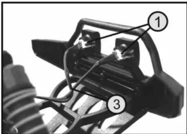
The package contains the lighting kit with two white LEDs (1) and two red LEDs (2). The LEDs come completely wired and equipped with a function switch. Like the steering servo or the speed controller, the lighting kit is connected to one of the remote control receiver's outputs.
If the receiver does not have a free output to connect the LEDs, use a V-cable (not included).
Installing the lighting kit
The bumpers come with suitable brackets for installing the LEDs. The LEDs just need to be pressed in from the inside of the bumper. Finally, the LEDs are fastened securely in the bumper with small locking latches.
First, connect the lighting kit to the receiver for test purposes and then put the receiver into operation. Then you can see which LEDs should be installed at the front and rear.
Then lay the cables (3) in the model so that the on/off switch is easy to operate and the cables can neither disturb the function of the model nor be damaged by vibrations or friction. Use the supplied adhesive pads for the switch and small cable ties for the cables.
text_image
Technical diagram of a mechanical assembly with numbered components labeled 1, 2, and 3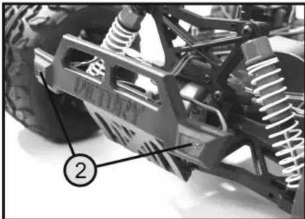
natural_image
Close-up of a mechanical vehicle chassis with springs and suspension components (no visible text or symbols)Figure 1
b) Setting the remote control and speed controller
You must adhere strictly to the manufacturer's instructions when setting the remote control and programming the speed controller.
The steering must be set so that the model moves straight ahead when the steering control on the transmitter is in the middle position. The steering deflection to the right and left must be the same and the steering and wheels should not touch at the full steering angle.
The speed controller must be set so that the motor is switched off when the driving function control on the transmitter is in the middle position. Additionally, driving functions such as full throttle or brakes must be reliably detectable by the speed controller so that the motor can be controlled accordingly.
c) Decorating the chassis
The kit comes with various stickers for the windows, headlights, rear lights and air intakes. The position of the stickers can be recognized easily by the shape of the stickers. In case of doubt, refer to the illustration on the packaging or illustrations in the Conrad Shop, if necessary. The remaining stickers, like those with the inscriptions "New 1", can be attached individually to the model.
10. Setting up the chassis
Before the first test drive, the chassis must be checked and, if necessary, adjusted.
The relationship between chassis setup and driving behaviour is very complex and beyond the scope of these operating instructions. For this reason, we can only show the setting options provided.
For further information, refer to relevant specialised magazines as well as comprehensive reference books on the subject matter.
a) Configuring the camber
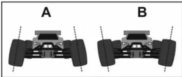
The camber is the inclination of the wheels as viewed from the front (vertical).
A negative camber means that the wheels have their upper edges facing inwards (see Figure 2A).
A positive camber means that the wheels have their upper edges facing outwards (see Figure 2B).
natural_image
Two identical illustrations of a toy car with wheels, labeled A and B, shown side by side without any text or symbols.two illustrations
Figure 2
The configuration of the wheels in the shown in Figure 2 is exaggerated to clearly show the difference between a negative and a positive camber.
Extreme settings should be avoided when configuring the model vehicle.
A negative camber on the front wheels increases the cornering forces of the wheels when performing turning manoeuvres. The steering responds more directly and the steering forces are lower. At the same time, the wheel is pushed onto the axle leg in the direction of the axis. This reduces axial bearing clearance and makes the driving behaviour smoother.
A negative camber on the rear wheels reduces the tendency of the rear of the vehicle to swing when turning corners. However, a positive camber reduces the cornering forces of the tyres and should not be used.
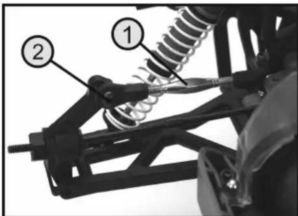
The rear axle can be configured by adjusting the length of the upper suspension arm (1). Because the adjusting screws of the upper suspension arms have left and right-hand threads, there is no need to remove the suspension arms for adjustment. Just turn the screw either to the left or right to adjust the length of the suspension arms.
If necessary, remove the screw on the steering knuckle (2) and screw it into another hole. The adjusting screw of the suspension arm can then be used for fine adjustment.
If you place the model vehicle on a flat surface, you can easily check whether a wheel has a positive or negative camber by using a large triangle ruler or an angle.
text_image
Technical diagram of a vehicle suspension system with labeled components 1 and 2Figure 3
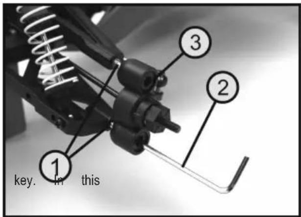
Adjust the front axle by turning the upper/lower pivot ball screws (1). To do this, use a 2.5 mm Hex key (2). Make sure that at least two-thirds of the threads of the pivot ball screws remain in the suspension arm.
Be sure to also check the play in the pivot ball screws whilst adjusting. If necessary, adjust the plastic inserts (3) with a 5 mm Hex key if the pivot ball screws are too stiff or if there is excessive play in the bearing.

The pivot ball screws can be accessed through the wheel rim using a long Hex case, you can check the modified configuration very quickly.
text_image
key. in thisFigure 4
b) Configuring the tyre track
When configuring the tyre track, the position of the wheel plane is adjusted to the direction of travel.
In this case, two distinctions are made:
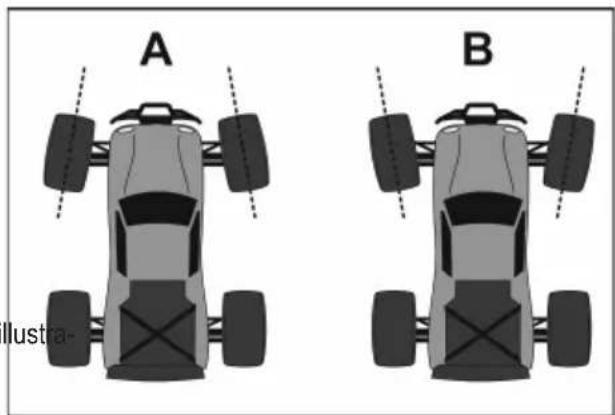
A toe-in means that the front wheels are facing slightly inwards (see Figure 5A).
A toe-out means that the front wheels are facing slightly outwards (see Figure 5B).
The configuration of the front wheels in the two tions shown above is exaggerated to clearly show the dif-ference between a toe-in and a toe-out. Extreme settings must be avoided when configuring the model vehicle!
A toe-in contributes to a better lateral guidance of the tyre and therefore to a more direct steering response. It also effectively supports directional stability.
natural_image
Two identical cartoon-style cars labeled A and B, shown from top-down perspective with dashed lines indicating side details (no text or symbols on the cars themselves)Figure 5
If desired, a smoother steering response can be achieved by configuring a toe-out accordingly.
A toe angle of 0^ on the front axle ensures the best driveability on almost any surface. A toe-in or toe-out angle of more than 3^ leads to problems in handling and reduced speed.
Before you adjust the tie rods. Check the position of the steering or the steering linkage (see Figure 31 in the assembly instructions). When the servo lever is at 90° to the servo, both wheels should be aligned identically. If the wheels have a slight left or right steering deflection, first adjust the steering linkage. If necessary, mount the steering linkage on the servo and adjust to the required length.
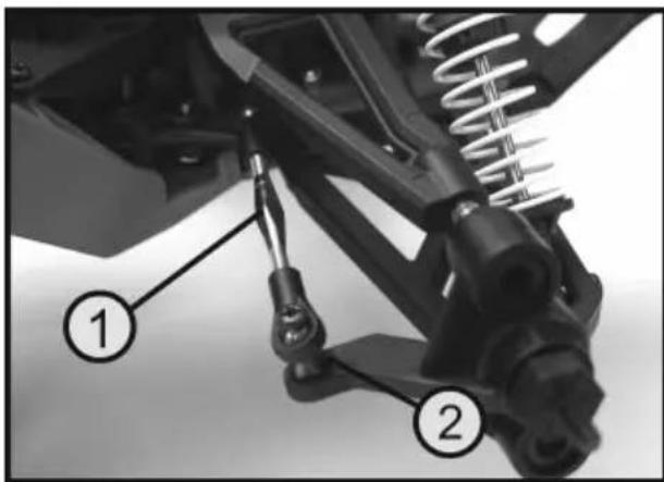
The toe-in/out on the front axle can be adjusted by turning the tie rods (1). Because the tie rods have left and right-hand threads, there is no need to remove them for adjustment. Always turn both tie rods (left and right front wheels) evenly; otherwise, the previously adjusted steering configuration will no longer fit.
The steering knuckle has another attachment point for the tie rod. It serves to adjust the turning angle of the front wheel (Ackermann angle) since the inside wheel requires a larger steering angle.
The rear axle toe is preset and cannot be changed.
text_image
Technical diagram of a vehicle suspension system with labeled components 1 and 2Figure 6
c) Adjusting the shock absorbers
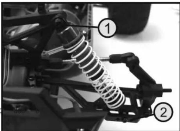
There are different mounting points for the shock absorbers at the top of the shock absorber bridges (1) and on the lower suspension arms (2). The ground clearance and the damping behaviour can thus be adjusted depending on the installation.
The final settings always depend on the preferable route of the model. If necessary, you can try different settings and thus gain hands-on experience of the driving behaviour of the model.
Experienced model vehicle operators can also opportunity to customise the shock absorbers. For this purpose, hard damping springs and shock absorber oils with different viscosity are commercially available.
text_image
Labeled mechanical assembly diagram showing a spring-loaded vehicle with numbered componentsFigure 7
11. Getting started with the model vehicle
Follow exactly the procedure described below to ensure that the vehicle does not make uncontrolled movements during commissioning.
- Just like the drive rechargeable battery, the batteries or rechargeable batteries in the transmitter must be full or fully charged.
- Remove the four chassis clips and lift off the chassis.
- Insert the charged drive rechargeable battery into the battery compartment and secure it with the Velcro straps.
- Switch on the remote control transmitter.
- Connect the drive rechargeable battery to the speed controller. If the speed controller has an additional on/off switch, turn it on.
- Check the steering function and the driving function. Place the model on a suitable base or service stand so that the wheels can turn freely.
- Replace the chassis on the mounts and secure the mounts with the chassis clips.
- For the first test drive, choose a sufficiently large area so that the model does not hit an obstacle in the event of a control error and get damaged.
- Start carefully until you get used to the driving behaviour of the vehicle.
• After the drive, first disconnect the drive rechargeable battery from the speed controller and then switch off the remote control.

Important!
witch off the transmitter when the drive rechargeable battery is connected to the model or the model is turned on.
12. Maintenance and cleaning
a) General information
Before cleaning or maintenance, turn off the speed controller and completely disconnect the drive rechargeable battery. Allow all parts to cool down completely (e.g. engine and speed controller).
After you have finished using the vehicle, remove all dust and dirt (e.g. using a clean long-haired brush and a vacuum cleaner). Compressed air sprays are also a good option. Do not use cleaning sprays or conventional household cleaning chemicals. These may damage the electronic components and discolour the plastic parts or chassis.
Never wash the vehicle with water, e.g. with a high-pressure cleaner. It destroys the motor, the speed controller and the receiver. Use a soft, slightly damp cloth to wipe the chassis. Do not rub too hard, as this may result in scratch marks.
b) Before and after each use
Engine vibrations and impacts during driving may cause certain parts and screw fittings to become loose. Before and after each use, check the following:
• All wheel nuts and screw fittings must be secure
• The speed controller, on/off switch, and receiver must be fixed
- Check the condition of the tyres and ensure that they adhere to the wheel rims
- Check that all cables are attached (they should not touch moving parts of the vehicle)
Check the vehicle for any signs of damage before and after each use. If there are any signs of damage, discontinue use immediately. Only use genuine spare parts when replacing worn vehicle parts (e.g. tyres) or defective vehicle parts (e.g. a broken suspension arm).
c) Adjusting the backlash
During assembly, servicing or repair works, it is necessary to check or adjust the backlash between the motor pinion and the main gear. The gears must mesh securely without any play or jamming.
To adjust the backlash, proceed as follows:
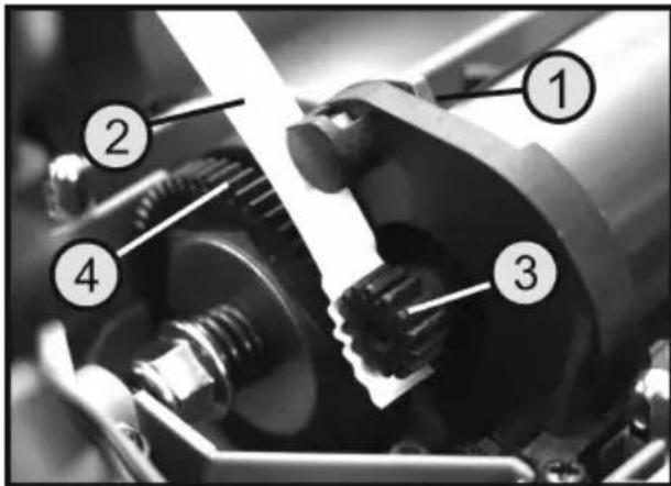
Remove the gear cover and loosen the upper motor mounting screw (1).
Place a thin paper strip (2) between the motor pinion (3) and the main gear (4).
Press the motor pinion against the main gear and tighten the upper motor mounting screw.
After removing the paper strip, the main gear can be turned by hand. Both gears must mesh securely without jamming.
text_image
Technical diagram of a mechanical assembly with numbered components labeled 1, 2, 3, and 4Figure 8
d) Adjusting the slip clutch
The slip clutch protects the gear and the motor from overloading during start-up, for example, on a surface with very good grip. In addition, adjustment of the slip clutch prevents the vehicle from tipping over due to the high torque of a hypothetical brushless drive when starting-up.
Normally, there is no need to make any adjustment because the manufacturer has already chosen an optimal one. However, very frequent start-ups with full power on a surface with good grip can cause the slip clutch linings to wear off, whereby a readjustment of the slip clutch may be required. Furthermore, experienced operators can individually adjust the slip clutch based on their preferred starting behaviour on a specific surface.
To adjust the clutch, proceed as follows:
First, remove the plastic gear cover.
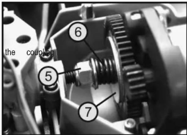
Place a 10 mm open-end wrench on the locknut (5) of the slip clutch. If you turn the nut to the right (as viewed from behind in the direction of travel), the compression spring (6) will exert greater contact pressure on plate (7). As a result, the slip point will move up and a higher drive power will be conveyed to both differentials.
If you turn the nut to the left, the compression spring will exert less pressure and the clutch will slip earlier.
text_image
the coupling ⑤ ⑥ ⑦Figure 9

Important!
lip clutch is overtightened, there is a risk that the model will tip over during rapid acceleration on a surface with good grip. In addition, the power train with differentials and the motor will be overloaded. This leads to an excessive wear of the components.
If the clutch is set too loose, the motor power cannot be fully utilised for propulsion. The clutch will be overloaded due to early slippage and can thus be destroyed.

Any adjustments that may be required in this area should only be made in small steps. A test drive can help you check the practicality of the new adjustment.
13. Disposal
a) Product

Electronic devices are recyclable waste and must not be disposed of in the household waste. At the end of its service life, dispose of the product according to the relevant statutory regulations.
Remove any inserted (rechargeable) batteries and dispose of them separately from the product.
b) (Rechargeable) batteries
You as the end user are required by law (Battery Ordinance) to return all used batteries/rechargeable batteries. Disposing of them in the household waste is prohibited.

Contaminated (rechargeable) batteries are labelled with this symbol to indicate that disposal in the domestic waste is forbidden. The designations for the heavy metals involved are: Cd = Cadmium, Hg = Mercury, Pb = Lead (name on (rechargeable) batteries, e.g. below the trash icon on the left).
Used (rechargeable) batteries can be returned to collection points in your municipality, our stores or wherever (rechargeable) batteries are sold.
You thus fulfil your statutory obligations and contribute to environmental protection.
14. Technical data
Scale....1:10
Suitable drive rechargeable
battery types....2-cell LiPo drive battery (nominal voltage 7.4 V)
6-cell NiMH drive battery (nominal voltage 7.2 V)
7-cell NiMH drive battery (nominal voltage 8.4 V)
Select a drive rechargeable battery based on specifications of your speed controller. Please observe the operating instructions of your speed controller.
Drive ......Optional brushless or brushed electric motor of size 550
All-wheel drive via cardan shaft
Front and rear axle differential
Chassis....Independent suspension, double wishbones
Oil-filled shock absorbers with coil springs
Adjustable front wheel toe
Adjustable front and rear wheel camber
Tyre dimensions (W x ∅)....70 x 125 mm
Length....440 mm
Width 340 mm
Height 210 mm
Wheel base....275 mm
Ground clearance....50 mm
Weight 1798 g
→ The product dimensions and weight may vary slightly.
Page
France (email) : technique@conrad-france.fr
natural_image
Close-up of a heavy-duty toy vehicle chassis with visible springs and structural components (no text or symbols)Illustration 1
natural_image
Two identical illustrations of a toy car with front and side views, labeled A and B (no text or symbols on the vehicle itself)text_image
Technical diagram of a mechanical assembly with numbered components labeled 1, 2, and 3Illustration 4
text_image
A B differenceIllustration 5
text_image
Labeled mechanical assembly diagram showing a spring-loaded vehicle suspension system with numbered componentsIllustration 7
text_image
Technical diagram of a mechanical assembly with numbered components labeled 5, 6, and 7Illustration 9

Attention, important!
text_image
Technical diagram of a mechanical component with numbered parts labeled 1, 2, and 3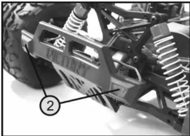
natural_image
Close-up of a mechanical vehicle chassis with visible springs and suspension components (no text or symbols)Afbeelding 1
natural_image
Two identical illustrations of a toy car with large tires, labeled A and B, shown side by side without any text or symbols.Afbeelding 2
text_image
Technical diagram of a vehicle suspension system with labeled components 1 and 2Afbeelding 3
text_image
Technical diagram of a mechanical assembly with numbered parts labeled 1, 2, and 3Afbeelding 4
natural_image
Two identical top-down diagrams of a toy car with wheels and suspension, labeled A and B (no text or symbols on the vehicles themselves)text_image
Technical diagram of a vehicle suspension system with labeled components 1 and 2Afbeelding 6
c) Schokdempers instellen
natural_image
Close-up of a vehicle suspension system with numbered components (1 and 2), no visible text or symbols beyond labelsAfbeelding 7
text_image
Technical diagram of a mechanical assembly with numbered components labeled 1, 2, 3, and 4Afbeelding 8
text_image
Technical diagram of a mechanical assembly with numbered components labeled 5, 6, and 7Afbeelding 9