
EWWQ025KBW1N - Water pump DAIKIN - Free user manual and instructions
Find the device manual for free EWWQ025KBW1N DAIKIN in PDF.

| Product type | Water pump (water-cooled chiller) |
| Brand | Daikin |
| Model | EWWQ025KBW1N |
| Category | Water pump |
| Dimensions (H x W x D) | 600 x 600 x 600 mm |
| Net weight | 170 kg |
| Power supply | 400 V three-phase (3N~) 50 Hz |
| Recommended fuses | 25 gG |
| Compressor rated current | 10.5 A |
| Refrigerant | R410A, 2.1 kg |
| Compressor oil type | FVC68D (3.0 L) |
| Compressor | JT236DJ-Y1, 2900 rpm |
| Evaporator | Brazed plate heat exchanger, min. water volume 103 L, flow rate 53-123 L/min |
| Condenser | Brazed plate heat exchanger, water flow 39-157 L/min |
| Water connections | Inlet and outlet G 1 |
| Safety | Phase reversal protection, overload relay, HP/LP pressure switches, thermal protector, antifreeze, flow switch |
| Main functions | Cooling and heating, digital control, configurable setpoint, maintenance timer |
| Digital control | LED display, navigation keys, direct and user parameters, optional Modbus connection |
| Maintenance | Annual check of connections, cleaning of water filter (mesh ≤ 1 mm), refrigerant leak check |
| Spare parts and repairability | Available from Daikin dealer; intervention by qualified technician |
| General information | Indoor installation, compliance with local standards, keep manual for future use |
Frequently Asked Questions - EWWQ025KBW1N DAIKIN
User questions about EWWQ025KBW1N DAIKIN
0 question about this device. Answer the ones you know or ask your own.
Ask a new question about this device
Download the instructions for your Water pump in PDF format for free! Find your manual EWWQ025KBW1N - DAIKIN and take your electronic device back in hand. On this page are published all the documents necessary for the use of your device. EWWQ025KBW1N by DAIKIN.
USER MANUAL EWWQ025KBW1N DAIKIN
Packaged water-cooled water chillers

| Operation manual Packaged water-cooled water chillers | English |
| Bedienungsanleitung Kompakte wassergeühte Kaltwassererzeuger | Deutsch |
| Manuel d'utilisation Groupes d'eau glacée refroidis par eau | François |
| Gebruiksaanwijzing Watergekoelde ijswaterkoelgroepen | Nederland |
| Manual de funciona Enfriadores de agua empaquetados | Espanol |
| Manuale d'uso Refrigeratori d'acqua monoblocco con raffreddamento ad agua | Italiano |
| Éyειρίδι Λειουργίας Συγκροτήματα Μβρόψικτων ψικτών ερού | Ελληνία |
| EWWQ014KBW1N EWWQ025KBW1N EWWQ033KBW1N EWWQ049KBW1N EWWQ064KBW1N | Manual de operation Refrigeradores de agua arrefecidos a agua Инструкция по заclпунатузii Монооблочье чимлеры в с BodянбIM охлajдениem portugues pyсsekni |
CONTENTS Page
Introduction 1
Technical specifications 1
Electrical specifications 2
Description 2
Function of the main components. 3
Safety devices. 3
Internal wiring - Parts table. 4
Before operation 5
Checks before initial start-up 5
Water supply. 5
General recommendations 5
Operation 5
Digital controller 5
Working with the units 6
Advanced features of the digital controller 9
BMS connection modbus 12
General description of Modbus. 12
Implemented error code 13
Defining the BMS setting. 13
Variables database 13
Troubleshooting. 14
Maintenance. 15
Important information regarding the refrigerant used 15
Maintenance activities 15
Disposal requirements 15
Menu overview. 16

READ THIS MANUAL ATTENTIVELY BEFORE STARTING UP THE UNIT. DO NOT THROW THIS MANUAL AWAY. KEEP IT IN YOUR FILES FOR FUTURE REFERENCE.
Read the chapter "Operation" on page 5 before changing the parameters.
The English text is the original instruction. Other languages are translations of the original instructions.
This appliance is not intended for use by persons, including children, with reduced physical, sensory or mental capabilities, or lack of experience and knowledge, unless they have been given supervision or instruction concerning use of the appliance by a person responsible for their safety.
Children should be supervised to ensure that they do not play with the appliance.
INTRODUCTION
This operation manual concerns packaged water-cooled water chillers of the Daikin EWWQ-KB series. These units are provided for indoor installation and used for cooling and/or heating applications. The units can be combined with Daikin fan coil units or air handling units for air conditioning purposes. They can also be used for supplying water for process cooling.
This manual has been prepared to ensure adequate operation and maintenance of the unit. It will tell you how to use the unit properly and will provide help if problems occur. The unit is equipped with safety devices, but they will not necessarily prevent all problems caused by improper operation or inadequate maintenance.
In case of persisting problems contact your local Daikin Dealer.

Before starting up the unit for the first time, make sure that it has been properly installed. It is therefore necessary to carefully read the installation manual supplied with the unit and the recommendations listed in "Before starting".
Technical specifications(1)
| General EWWQ 014 025 033 | |
| Dimensions HxWxD (mm) | 600x600x600 |
| Machine weight (kg) | 120 170 175 |
| Connections | |
| ·w a t er inlet | G 1 |
| ·w a t er outlet | G 1 |
| General EWWQ | 049 | 064 | |
| Dimensions HxWxD | (mm) | 600x600x1200 | |
| Machine weight | (kg) | 310 | 340 |
| Connections | |||
| • w a t er inlet | G 1-1/2 | ||
| • w a t er outlet | G 1-1/2 | ||
| Compressor | 014 025 033 | |||
| Model | JT140L-P8Y1 | JT236DJ-Y1 | JT315DJ-Y1 | |
| Speed | (rpm) | 2900 | ||
| Oil type | FVC68D | |||
| Oil charge volume | (l) | 1.5 | 3.0 | 3.0 |
| Refrigerant type | R410A | |||
| Refrigerant charge | (kg) | 1.2 | 2.1 | 3.1 |
| Evaporator | 014 025 033 | |||
| Type | brased plate heat exchanger | |||
| Min. water volume | (l) | 62 | 103 155 | |
| Water flow range | (l/min) | 31~75 | 53~123 | 76~186 |
| Condenser | 014 025 033 | |||
| Type | brased plate heat exchanger | |||
| Water flow range | (l/min) | 24~95 | 39~157 | 59~237 |
| Compressor | 049 | 064 | |
| Model | 2x JT236DJ-Y1 | 2x JT315DJ-Y1 | |
| Speed | (rpm) | 2900 | |
| Oil type | FVC68D | ||
| Oil charge volume | (l) | 2x 3.0 | 2x 3.0 |
| Refrigerant type | R410A | ||
| Refrigerant charge | (kg) | 4.6 | 5.6 |
| Evaporator | 049 | 064 | |
| Type | braced plate heat exchanger | ||
| Min. water volume | (l) | 205 | 311 |
| Water flow range | (l/min) | 101~247 | 152~373 |
| Condenser | 049 | 064 | |
| Type | braced plate heat exchanger | ||
| Water flow range | (l/min) | 79~314 | 118~474 |
(1) Refer to the engineering data book for the complete list of specifications.
Electrical specifications(1)
General EWWQ014 025 033
| Power supply | ||||
| • Phase 3N~ | ||||
| • Frequency | (Hz) | 50 | ||
| • Voltage | (V) | 400 | ||
| • Voltage tolerance | (%) | ±10 | ||
| • Recommended fuses | (aM) | 16 gG | 25 gG | 25 gG |
| Compressor | ||||
| • Phase 3~ | ||||
| • Frequency | (Hz) | 50 | ||
| • Voltage | (V) | 400 | ||
| • Nominal running current | (A) | 6.5 | 10.5 | 15.0 |
| Control | ||||
| • Phase 1~ | ||||
| • Frequency | (Hz) | 50 | ||
| • Voltage | (V) | 230 | ||
| • Recommended fuses | (aM) | factory installed | ||
| General EWWQ | 049 | 064 | |
| Power supply | |||
| • Phase | 3N~ | ||
| • Frequency (Hz) | 50 | ||
| • Voltage (V) | 400 | ||
| • Voltage tolerance (%) | ±10 | ||
| • Recommended fuses (aM) | 40 gG | 50 gG | |
| Compressor | |||
| • Phase | 3~ | ||
| • Frequency (Hz) | 50 | ||
| • Voltage (V) | 400 | ||
| • Nominal running current (A) | 10.5 | 15.0 | |
| Control | |||
| • Phase | 1~ | ||
| • Frequency (Hz) | 50 | ||
| • Voltage (V) | 230 | ||
| • Recommended fuses (aM) | factory installed | ||
DESCRIPTION
The EWWQ packaged water-cooled water chillers are available in 5 standard sizes with nominal cooling capacities ranging from 13 to 64kW
EWWQ014~033KB
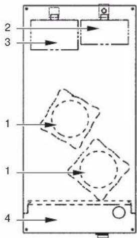
EWWQ049~064KB
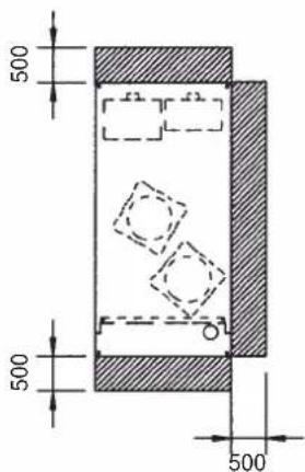
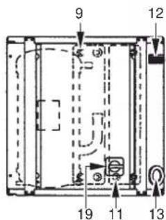
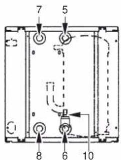
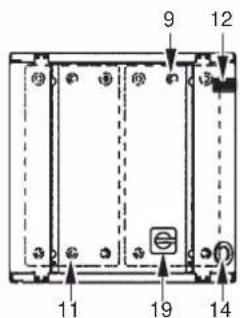
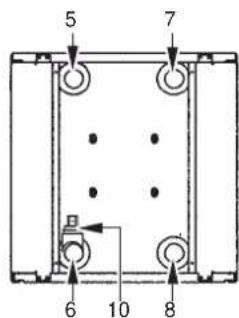
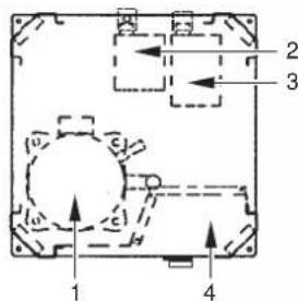
Figure - Main components
1 Compressor
2 Evaporator
3 Condenser
4 Switchbox
5 Chilled water in
6 Chilled water out
7 Condenser water out
8 Condenser water in
9 Evaporator entering water temperature sensor
10 Freeze up sensor
11 Condenser entering water temperature sensor
12 Digital display controller
13 Power supply intake
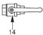
14 Ball valve (field installed)
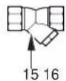
15 Water filter (field installed)
16 Air purge valve (field installed)
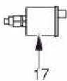
17 T-joint for air purge (field installed)
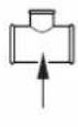
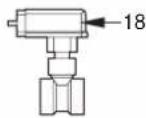
18 Flow switch (with T-joint) (field installed)
19 Main switch
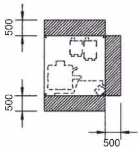
Required space around the unit for service
Function of the main components
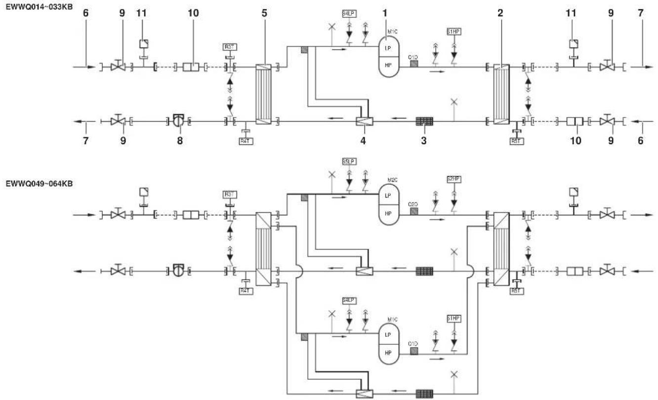
Figure - Functional diagram
1 Compressor 7 Water outlet
2 Condenser
3 Filter
4 Expansion valve
5 Evaporator
6 Water inlet Field piping
As the refrigerant circulates through the unit, changes in its state or condition occur. These changes are caused by the following main components:
Compressor
The compressor (M^*C) acts as a pump and circulates the refrigerant in the refrigeration circuit. It compresses the refrigerant vapour coming from the evaporator to a pressure at which it can easily be liquefied in the condenser.
Condenser
The function of the condenser is to change the state of the refrigerant from gaseous to liquid. The heat gained by the gas in the evaporator is discharged through the condenser and the vapour condenses to liquid.
Filter
The filter installed behind the condenser removes small particles from the refrigerant to prevent blockage of the tubes.
Expansion valve
The liquid refrigerant coming from the condenser enters the evaporator via an expansion valve. The expansion valve brings the liquid refrigerant to a pressure at which it can easily be evaporated in the evaporator.
Evaporator
The main function of the evaporator is to take heat from the water that flows through it. This is done by turning the liquid refrigerant, coming from the condenser, into gaseous refrigerant.
Water in/outlet connections
The water inlet and outlet connection allow an easy connection of the unit to the water circuit of the air handling unit or industrial equipment.
8 Flow switch (delivered with the unit, installed in the field)
9 Ball valve (delivered with the unit, installed in the field)
10 Water filter (delivered with the unit, installed in the field)
Air purge valve (delivered with the unit, installed in the field)
Safety devices
The unit is equipped with General safety devices: shut down all circuits and stop the whole unit.
I/O PCB (A2P) (input/output)
The I/O PCB (A2P) contains a reverse phase protector. The reverse phase protector detects if the 3 phases of the power supply are connected correctly. If a phase is not connected or if 2 phases are inverted, the unit can not start up.
Overcurrent relay
The overcurrent relay (K^*S) is located in the switch box of the unit and protects the compressor motor in case of overload, phase failure or too low voltage. The relay is factory-set and may not be adjusted. When activated, the overcurrent relay has to be reset in the switch box and the controller needs to be reset manually.
High-pressure switch
The high-pressure switch (S^*HP) is installed on the discharge pipe of the unit and measures the condenser pressure (pressure at the outlet of the compressor). When the pressure is too high, the pressure switch is activated and the circuit stops.
When activated, it resets automatically, but the controller needs to be reset manually.
Low pressure switch
The low-pressure switch (S*LP) is installed on the suction pipe of the unit and measures the evaporator pressure (pressure at the inlet of the compressor). When the pressure is too low, the pressure switch is activated and the circuit stops.
When activated, it resets automatically, but the controller needs to be reset manually.
Discharge thermal protector
The discharge thermal protector (^*) is activated when the temperature of the refrigerant leaving the compressor becomes too high. When the temperature returns to normal, the protector resets automatically, but the controller needs to be reset manually.
Freeze up sensor
The outlet water temperature sensor (R4T) measures the temperature of the water at the water heat exchanger outlet. The protection device shuts down the circuit when the temperature of the chilled water becomes too low in order to prevent freezing of the water during operation.
When the outlet water temperature returns to normal, the protector resets automatically, but the controller needs to be reset manually.
Fuse for control circuit (F1U)
The fuse for control circuit protects cables of control circuit and controller components in case of short circuit.
Fuse for control circuit (F4)
The fuse for the control circuit protects cables of the control circuit in case of a short circuit.
Fuse for digital controller (F3U)
The fuse protects cables of digital controller and digital controller in case of short circuit.
Flow switch (delivered with the unit, installed in the field)
The flow switch measures the flow in the water circuit. In case the flow does not reach the minimum allowed water flow, the unit will be shut down.
Ball valve (delivered with the unit, installed in the field)
A ball valve is installed in front of and behind the water filter to allow filter cleaning without having to drain the water circuit.
Water filter (delivered with the unit, installed in the field)
The filter installed in front of the unit removes dirt from the water to prevent damage to the unit or blockage of the evaporator or condenser. The water filter should be cleaned on a regular base.
Air purge valve (delivered with the unit, installed in the field)
Remaining air in the chiller water system will be automatically removed via the air purge valve.
Internal wiring - Parts table
Refer to the internal wiring diagram supplied with the unit. The abbreviations used are listed below:
A1P. PCB: controller PCB
A2P. PCB: I/O PCB (input/output)
A3P. .PCB:Address card for BMS(1)
A5P,A6P. .PCB: Softstarter for circuit 1, circuit 2(1)
A7P. .PCB:Remote user interface(1)
A71P. PCB: power supply card
A72P. PCB: remote user interface
F1,F2,F3....#.... Main fuses for the unit(2)
F4 . Fuse I/O PCB
F5....Surge proof fuse
F6.........#....Fuse for pumpcontactor(2)
F1U....Fuse I/O PCB
F3U. Fuse for controller PCB
H3P. Indication lamp alarm(2)
H4P. Indication lamp operation compressor 1(2)
H5P. Indication lamp operation compressor 2(2)
H6P. .Indication lamp general operation(2)
K1M,K2M.. Compressor contactor circuit 1, circuit 2
K4S,K5S.... Overcurrent relay circuit 1,circuit 2
K6S. .Overcurrent relay pump(2)
K1P. . Pumpcontactor
M1C,M2C. .Compressor motor circuit 1,circuit 2
PE. Main earth terminal
Q1D,Q2D Discharge thermal protector circuit 1, circuit 2
R3T. .Evaporator inlet water temperature sensor
R4T. Evaporator outlet water temperature sensor
R5T........... Condenser inlet temperature sensor
S1HP,S2HP. High pressure switch circuit 1,circuit 2
S4LP,S5LP. Low pressure switch circuit 1,circuit 2
S7S.... Switch for remote cooling/heating selection or dual setpoint(2)
S9S. Switch for remote start/stop or dual setpoint(2)
S10L . Flow switch
S12M Main isolator switch
TR1. Transfo 230V 24V for supply of controller PCB
TR2. Transfo 230V 24V for supply of I/O PCB (A2P)
Y3R. Reversing valve
X1~3,X1~82A ....... Connectors
| Not included with standard unit | ||
| Not possible as option | Possible as option | |
| Obligatory # ## | ||
| Not obligatory * * | ||
(1) optional
(2) field supply
BEFORE OPERATION
Checks before initial start-up

Make sure that the circuit breaker on the power supply panel of the unit is switched off.
After the installation of the unit, check the following before switching on the circuit breaker:
1 Field wiring
Make sure that the field wiring between the local supply panel and the unit has been carried out according to the instructions described in the installation manual, according to the wiring diagrams and according to European and national regulations.
2 Fuses or protection devices
Check that the fuses or the locally installed protection devices are of the size and type specified in the installation manual. Make sure that neither a fuse nor a protection device has been bypassed.
3 Earth wiring
Make sure that the earth wires have been connected properly and that the earth terminals are tightened.
4 Internal wiring
Visually check the switch box on loose connections or damaged electrical components.
5 Fixation
Check that the unit is properly fixed, to avoid abnormal noises and vibrations when starting up the unit.
6 Damaged equipment
Check the inside of the unit on damaged components or squeezed pipes.
7 Refrigerant leak
Check the inside of the unit on refrigerant leakage. If there is a refrigerant leak, call your local dealer.
8 Oil leak
Check the compressor on oil leakage. If there is an oil leak, call your local dealer.
9 Power supply voltage
Check the power supply voltage on the local supply panel. The voltage should correspond to the voltage on the identification label of the unit.
Water supply
Fill the water piping, taking into account the minimum water volume required by the unit. Refer to the chapter "Water charge, flow and quality" in the installation manual.
Make sure that the water is of the quality as mentioned in the installation manual.
Purge the air at the high points of the system and check the operation of the circulation pump and the flow switch.
General recommendations
Before switching on the unit, read following recommendations:
1 When the complete installation and all necessary settings have been carried out, close all front panels of the unit.
2 The service panel of the switch box may only be opened by a licensed electrician for maintenance purposes.
OPERATION
The EWWQ units are equipped with a digital controller offering a user-friendly way to set up, use and maintain the unit.
This part of the manual has a task-oriented, modular structure. Apart from the first section, which gives a brief description of the controller itself, each section or subsection deals with a specific task you can perform with the unit.
Digital controller
User interface
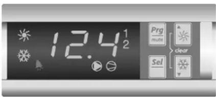
The digital controller consists of a numeric display, four labelled keys which you can press and LEDs providing extra user information.

Figure - Digital controller
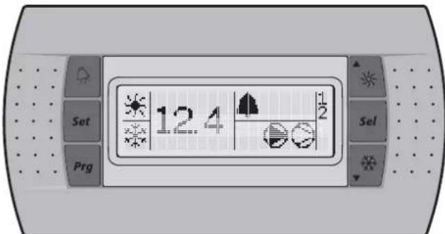
Figure - Remote user interface (optional kit)
Keys provided on the controller:
The function carried out when the user presses one or a combination of these keys depends on the status of the controller and the unit at that specific moment.
| Keys digital controller | Keys remote interface | Main display | Sensor readout menu | Parameter selection menu | Parameter setting menu |
| Png+ | Png | — Press once: | Return | Press once: Return | Press once: Cancel and return |
| Saf! | Saf | Press for 5 seconds: To be able to access DIRECT parameters | — | Press once: Select parameter group or parameter | Press once: Confirm and return |
| Png+/Saf+ | + Saf | Press for 5 seconds: Png+/Saf+ OR Press once: Saf To be able to access USER parameters (after entering USER password) | — | ||
| ▲Saf | ▲Saf | Press for 5 seconds: Switch unit on/off in heating mode Press once: Direct access to readout menu sensor (b0 1/b02/b03) | Press once: Select previous sensor parameter | Press once: Select previous parameter group or parameter | Press once: Increase value |
| Saf▼ | Saf▼ | Press for 5 seconds: Switch unit on/off in cooling mode Press once: Direct access to readout menu sensor (b0 1/b02/b03) | Press once: Select next sensor parameter | Press once: Select next parameter group or parameter | Press once: Decrease value |
| ▲Saf + Saf▼ | + Saf▼ | Press for 5 seconds: Manually alarm reset in the event of alarm | — | ||
LEDs provided on the controller and remote interface:
Function during main display (not inside menu)
| Remote | |||
| Leds digital controller | interface | ||
| 12.4 | Led (green) 12 | 4 Inlet water temp | erature. |
| ※ | Led (amber) | ※ | Indicates that heating mode is active. |
| Led (amber)※ | Indicates that cooling mode is active. | ||
| ※ | Led (red) | ▲ | Indicates that the alarm is active. |
| ● | Led (amber) | ● | Indicates the status of the pump |
| ○ | Led (amber) | ○ | LED, indicates that at least one compressor is active. |
| 1 | Led (amber) | 1 | LED is on, indicates that compressor 1 is active. LED is flashing, indicates compressor 1 startup request. |
| 2 | Led (amber) | 2 | LED is on, indicates that compressor 2 is active. LED is flashing, indicates compressor 2 startup request. |
When selecting a parameter group or parameter, different LEDs related to the parameter group or parameter are displayed.
Example: The LEDs 喜 and 喜 are displayed when accessing a parameter group or when accessing parameters directly.
NOTE

Temperature readout tolerance: ± 1^
Legibility of the numeric display may decrease in direct sunlight.
Direct and user parameters
The digital controller provides direct and user parameters. The direct parameters are important for the everyday usage of the unit, e.g. to adjust the temperature setpoint or to consult actual operational information. The user parameters on the contrary provide advanced features such as adjusting time delays.
Each parameter is defined by a code and a value. For example: the parameter used to select local or remote on/off control has code H07 and value 1 or 0.
For an overview of the parameters, refer to "Overview of the direct and user parameters" on page 9.
Working with the units
This chapter deals with the everyday usage of the units. Here, you will learn how to perform routine tasks, such as:
"Switching the unit on" on page 7 and "Switching the unit off" on page 7.
"Adjusting the cooling temperature setpoint" on page 7 and "Adjusting the heating temperature setpoint" on page 7,
"Consulting actual operational information" on page 8,
"Resetting alarms" on page 8,
"Resetting warnings" on page 8.
Switching the unit on
To switch the unit on in cooling mode, proceed as follows:
1 Press the key for approximately 5 seconds, the LED will be displayed.
To switch the unit on in heating mode, proceed as follows:
1 Press the key for approximately 5 seconds, the LED will be displayed.
In both cases an initialization cycle is started, the LED, the LED, the 1 LED and the 2 LED will light up depending on the programmed thermostat function.
In case the 1 LED or the 2 LED is flashing, it indicates that there is a compressor 1 or 2 startup request. The compressor will start after the timer has reached zero.
NOTE

If remote on/off control is enabled, refer to "Selecting local or remote on/off control" on page 11.
2 When the unit is started up for the first time, or when the unit has been out of operation for a longer period, it is recommended to go through the following checklist.
Abnormal noise and vibrations
Make sure the unit does not produce any abnormal noises or vibrations: check the fixations and piping. If the compressor makes any abnormal noises, this may also be caused by an overcharge of refrigerant.
Working pressure
It is important to check the high and low pressure of the refrigerant circuit to ensure the proper operation of the unit and to guarantee that the rated output will be obtained.

The pressures measured will vary between a maximum and minimum value, depending on the water and outdoor temperatures (at the moment of measurement).
3 If the unit does not start after a few minutes, consult the actual operational information available in the list of direct parameters. Also refer to the chapter "Troubleshooting" on page 14.
NOTE

In case of remote on/off control (HOT = I) it is recommended to install an on/off switch near the unit in series with the remote switch. The unit can then be switched off from either place.
The selection of cooling mode or heating mode can only be carried out at startup. Selecting an opposite mode without switching the unit off is impossible.
Switching the unit off
To switch the unit off and cooling mode is active, proceed as follows:
1 Press the 念 key for approximately 5 seconds, the LED will be extinguished.
To switch the unit off and heating mode is active, proceed as follows:
1 Press the key for approximately 5 seconds, the LED will be extinguished.
NOTE

If remote on/off control is enabled, refer to "Selecting local or remote on/off control" on page 11.
How to consult and modify the direct parameters
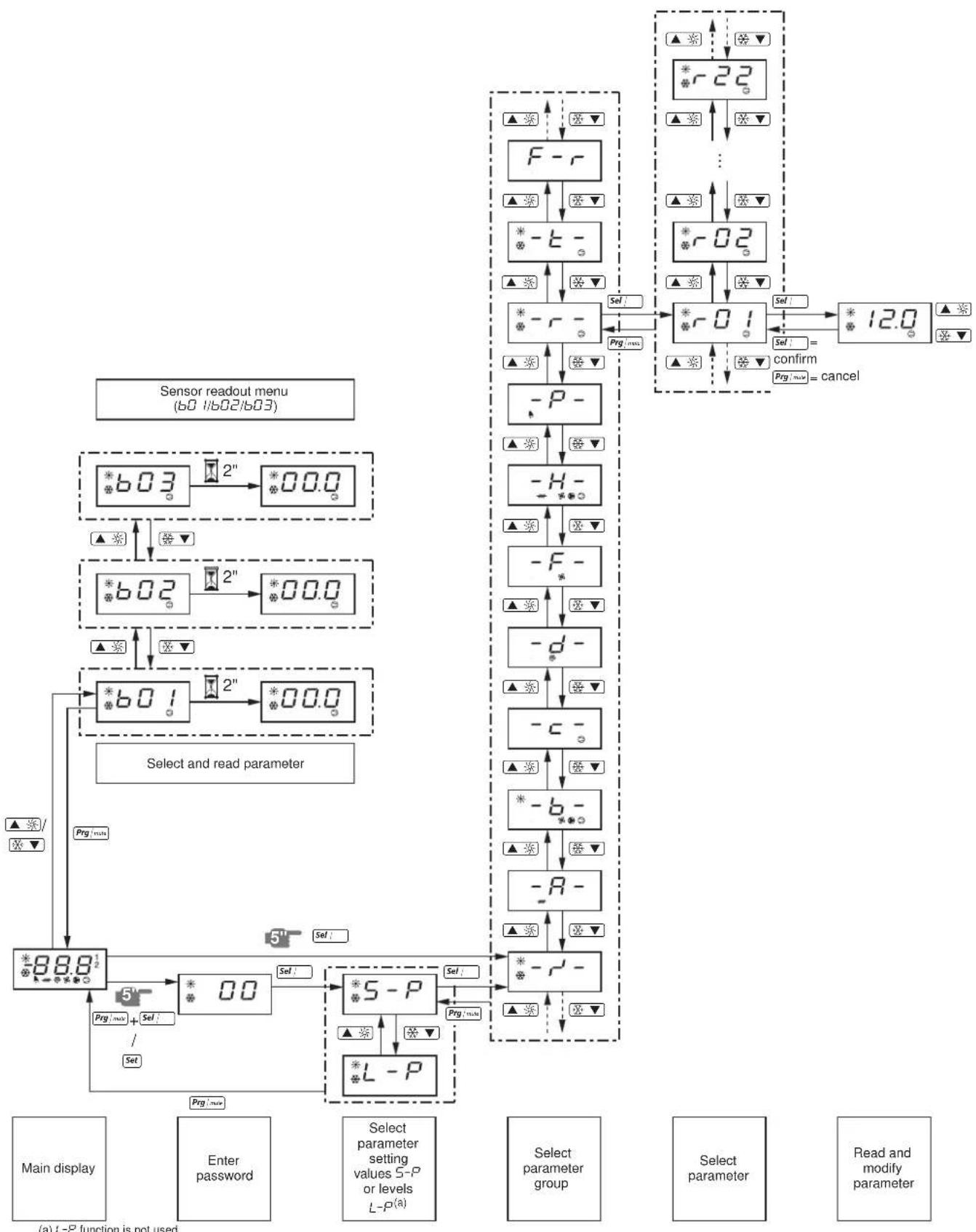
For an overview of the menu structure, refer to "Menu overview" on page 16.
1 Press [Sel] for 5 seconds in the main display. The -r parameter group is displayed.
2 Press the or key to select the required parameter group.
3 Press the key to enter the selected parameter group.
4 Press the or key to select the required parameter.
5 Press the key to consult the selected parameter.
6 Press the or key to raise, respectively lower the setting of the selected parameter. (Only valid for read/write parameters.)
7 Press the ^ key to confirm the modified setting. OR Press the ^+ + + key to cancel the modified setting.
8 Press the Prgmax^ key to return to the parameter group.
9 Press 2 times the g / n key to return to the main display.
If during the procedure no buttons are pressed for 30 seconds, the displayed parameter code or value will start flashing. After another 30 seconds without pressing any buttons, the controller automatically returns to the main display without saving any modified parameter.
How to consult the "sensor readout menu" parameters
For an overview of the menu structure, refer to "Menu overview" on page 16.
The b01/b02/b03 parameters are part of the "sensor readout menu".
1 Press the or key in the main display.
The b0 t parameter is displayed.
In case no buttons are pressed, the value of the b01 sensor will be displayed until or 空 is pressed again to select another parameter (b02 or b03).
2 Press the :m key to return to the main display.
If during the procedure no buttons are pressed for 30 seconds, the displayed parameter code or value will start flashing. After another 30 seconds without pressing any buttons, the controller automatically returns to the main display.
Adjusting the cooling temperature setpoint
1 Modify the r^ cooling setpoint parameter.
This is a direct parameter, refer to "How to consult and modify the direct parameters" on page 7.
NOTE

When dual setpoint is enabled (refer to "Selecting dual setpoint control" on page 11).
Adjusting the heating temperature setpoint
1 Modify the r -3 heating setpoint parameter.
This is a direct parameter, refer to "How to consult and modify the direct parameters" on page 7.
NOTE
When dual setpoint is enabled (refer to "Selecting dual setpoint control" on page 11).
Consulting actual operational information
The actual operational information that can be consulted in the list of direct parameters consists of:
b Evaporator inlet water temperature,
b02: Evaporator outlet water temperature,
b03: When cooling mode is active: inlet water temperature of the condenser. When heating mode is active: inlet water temperature of the evaporator.
- c 10: Total running hours of the compressor 1,
- Total running hours of the compressor 2,
- Total running hours of the pump.
NOTE

The parameters b01, b02 and b03 can also be consulted by the "sensor readout menu". Refer to "How to consult the "sensor readout menu" parameters" on page 7.
To reset the timers of parameters c / 10, c / 11 and c / 15 refer to "Resetting warnings" on page 8.
These are direct parameters, refer to "How to consult and modify the direct parameters" on page 7.
Resetting alarms
When an alarm is detected, the following happens:
the alarm relay is energized,
the LED is displayed
the display starts flashing, alternately showing the alarm code and the inlet water temperature.
The following alarm codes may appear on the screen:
B: i ndicates an anti-freeze alarm.
E: indicates that the NTC probe used to measure the evaporator inlet water temperature is defective.
- E2 : indicates that the NTC probe used to measure the evaporator outlet water temperature is defective.
E3: indicates that the fuse for the evaporator heatertape (F4) is blown or that there is a reverse phase error or that there is a problem with the I/O PCB (A2P).

In case the unit is equipped with freeze protection, it is highly recommended to install the remote indicator lamp alarm (H3P) (see wiring diagram supplied with the unit). By doing so, breakdown of the fuse for the evaporator heatertape (F4) will be detected sooner and freezing of the circuit will be avoided during cold weather.
EH5: indicates that the supply voltage is exceedingly high. In this case contact a licensed electrician.
EL: indicates that there is a power supply error (example: noise). In this case contact a licensed electrician.
EL2: indicates that there is a power supply error (example: noise). In this case contact a licensed electrician.
ELS: indicates that the supply voltage is exceedingly low. In this case contact a licensed electrician.
- EPb: indicates that the EEPROM on the controller PCB inside the unit is defective.
- E P_r : indicates that the EEPROM on the controller PCB inside the unit is defective.
FL: indicates that there was no sufficient water flow either during the period of 15 seconds after the pump was started or for 5 seconds while the compressor is active or that the overcurrent protection of the pump is activated.
HP1: indicates that a high pressure switch, the discharge thermal protection or the overcurrent protection of the compressor motor is activated or that the NTC probe used to measure the ambient temperature is defective.
■FL + HP: i ndicates that there is most likely an RPP error or that the F4 fuse is blown.
L P indicates that the low pressure switch is activated.
- EER: indicates that there is a remote user interface communication error.
- Offline: communication failure between the digital controller of the unit and the remote user interface. Confirm the correct selection of parameter code H23. This should be default setting 0 and confirm the correction installation according to the installation manual of the remote user interface EKRUMCA.
NOTE

If the alarm codes FL and H are flashing alternately, the alarm is most probably caused by the reverse phase protector or by the fuse for evaporator heater-tape (F4) that was blown.
To reset an alarm, proceed as follows:
1 Find the cause of shutdown and correct.
Refer to the chapter "Troubleshooting" on page 14.
2 If the alarm codes R , I , FL , HP or LP appear on the display, reset the alarm manually by pressing the clear combination keys
and simultaneously for approximately 5 seconds. In all other cases the alarm is reset automatically.
Once the alarm is reset, the error code and the LED no longer appears on the display. The controller continues its normal operation, displaying the inlet water temperature.
Resetting warnings
During normal operation, the display of the controller may start flashing, alternately showing the inlet water temperature and the following warning code:
- H I : indicates that the compressor 1 requires maintenance: the total running hours of the compressor 1 (direct parameter c / 10 ) has exceeded the setting of the timer threshold for maintenance warning (user parameter c / 14 ).
- Hc2: indicates that the compressor 2 requires maintenance: the total running hours of the compressor 2 (direct parameter c 1) has exceeded the setting of the timer threshold for maintenance warning (user parameter c 14).
To reset the maintenance warning H_c or H_c2 , proceed as follows:
1 Consult c iO running hours of compressor 1 or c t I running hours of compressor 2.
These are direct parameters, refer to "How to consult and modify the direct parameters" on page 7.
2 When c B or c I parameter value is displayed, press the and key simultaneously for 5 seconds. The value of the timer becomes B and the warning is reset.
NOTE

Do not forget to carry out the required maintenance activities after resetting the timers.
Besides resetting timer c口 and c口 , it is also possible to reset timer c口 (running hours of pump) in the same way.
Advanced features of the digital controller
This chapter gives an overview of the direct parameters and user parameters provided by the controller. In the following chapter, you will learn how you can set up and configure the unit using these parameters.
Overview of the direct and user parameters
The list of direct parameters is accessible by pressing the key for approximately 5 seconds. Refer also to "How to consult and modify the direct parameters" on page 7.
| Parameter group | Parameter code | Description | Default value | Min Max Units | Read/ Write | User/ Direct | Modbus Address | Parameter type(a) | ||
| -r--r23 | Measurement unit \( \theta =^{\circ}C i =^{\circ}F \) | 0 | 0 | 1 | R | / | W | U | ||
| -R- No user or direct parameters accessible | ||||||||||
| -b- | b0 i | Evaporator inlet water temperature | 0.1°C | R | D | 102 | A | |||
| b02 | Evaporator outlet water temperature | 0.1°C | R | D | 103 | A | ||||
| b03 | When cooling mode is active: inlet water temperature of the condenser. When heating mode is active: inlet water temperature of the evaporator. | 0.1°C R | D | 104 | A | |||||
| -c- | c07 | Time delay between pump startup and compressor startup | 15 | 0 | 999 | 1 sec | R/W | U | 238 | I |
| c08 | Time threshold between the unit shutdown and the pump shutdown | 0 | 0 | 150 | 1 min | R/W | U | 239 | I | |
| c 10 | Total running hours of compressor 1 | x100 hours | R | D | 122 | A | ||||
| c i 1 | Total running hours of compressor 2 | x100 hours | R | D | 123 | A | ||||
| c i 4 | Maintenance threshold for maintenance warning (c 10 and c i 1) | 0 | 0 | 100 | x100 hours | R/W | U | 241 | I | |
| c 15 | Total running hours of pump | x100 hours | R | D | 126 | A | ||||
| -d- No user or direct parameters accessible | ||||||||||
| -F- No user or direct parameters accessible | ||||||||||
| -H- | H0b | To activate remote cool/heat control\( \theta = \) not activei=active(only in case \( P09 = 9 \)) | 0 | 0 | 1 | R | / | W | U | |
| H07 | To activate remote on/off control\( \theta = \) not activei=active(only In case \( P34 = 23 \)) | 0 | 0 | 1 | R | / | W | U | ||
| H09 | To lock the controller keyboard\( \theta = \)locki=unlock | 1 | 0 | 1 | R | / | W | U | ||
| H 10 | Serial address for BMS connection | 1 | 1 | 200 | R/W | U | 256 | I | ||
| H23 | To select address card connection\( \theta = \)remote user interface connectioni=MODBUS connection | 0 | 0 | 1 | R | / | W | U | ||
| -P- | P09 | Changeable digital input selection S7S\( \theta = \) no function\( \theta = \) remote cool/heat (only active in combination with \( H05 \))i3=remote dual setpointDO NOT SELECT OTHER VALUES | 9 | 0 | 27 | R/W | U | 277 | I | |
| P34 | Changeable digital input selection S9S\( \theta = \) no functioni3=remote dual setpointi3=remote on/off (only active in combination with \( H07 \))DO NOT SELECT OTHER VALUES | 23 | 0 | 27 | R/W | U | 329 | I | ||
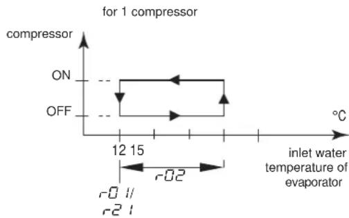
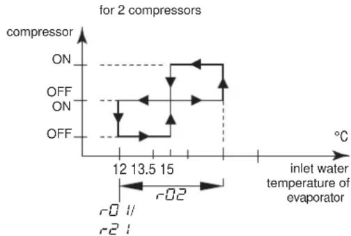
| -r- | r0 i | Cooling setpoint | 12.0 | \( 8.0^{(b)} \) | 25.0 | 0.1°C | R/W | D | 41 | A |
| r02 | Cooling difference | 3.0 | 0.3 | 19.9 | 0.1°C | R/W | D | 42 | A | |
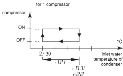
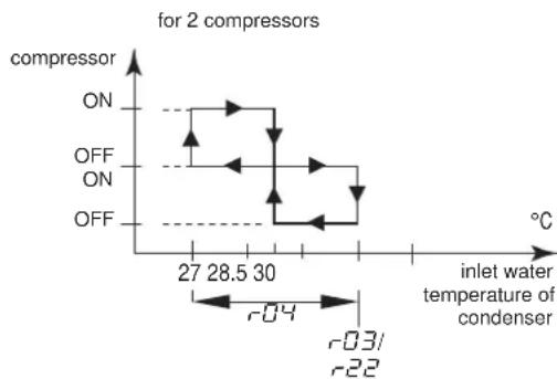
| r03 | Heating setpoint | 30.0 | 15.0 | 50.0 | 0.1°C | R/W | D | 43 | A | |
| r04 | Heating difference | 3.0 | 0.3 | 19.9 | 0.1°C | R/W | D | 44 | A | |
| r2 i | Cooling setpoint \( 2^{(c)} \) | 12.0 | \( 8.0^{(b)} \) | 25.0 | 0.1°C | R/W | D | 55 | A | |
| r22 | Heating setpoint \( 2^{(c)} \) | 30.0 | 15.0 | 50.0 | 0.1°C | R/W | D | 56 | A | |
| -E- No user or direct parameters accessible | ||||||||||
| -F-r | H99 | Software release version | R | D | 208 | I | ||||
(a) D=digital, A=analog, I=integer.
(b) -2.0 and -7.0 only applicable for units with glycol applications.
(c) Used in case dual setpoint is enabled in P09 or P34 and dual setpoint digital input is closed.

When user parameters are consulted, the direct parameters are displayed as well.
For an overview of the menu structure, refer "Menu overview" on page 16.
1 In case of digital controller, press the _i + 1 and _i keys for approximately 5 seconds until is displayed. In case of remote user interface, push set once.
2 Enter the correct password by using the and 空 keys. The password's value is 22.
3 Press the Sel key to confirm the password and to enter the menu, S - P is displayed.
4 Press the _i key to consult the parameter settings (= S - P) . (L - P means consulting the parameter level, but this function is not used). The -r^ - parameter group is displayed.
5 Press the or key to select the required parameter group.
6 Press the key to enter the selected parameter group.
7 Press the or key to select the required parameter.
8 Press the key to consult the selected parameter.
9 Press the or key to increase, respectively decrease the setting. (Only valid for read/write parameters.)
10 Press the key to confirm the modified setting. OR Press the key to cancel the modified setting.
11 Press the :mns key to return to the parameter group.
12 Press 2 times the key to return to the main display.
If during the procedure no buttons are pressed for 30 seconds, the displayed parameter code or value will start flashing. After another 30 seconds without pressing any buttons, the controller automatically returns to the main display without saving any modified parameter.
Modify the r -cooling differential parameter.
This is a direct parameter, refer to "How to consult and modify the direct parameters" on page 7.
Defining the heating temperature differential
Modify the r -heating differential parameter.
This is a direct parameter, refer to "How to consult and modify the direct parameters" on page 7.
Defining the measurement unit
Depending on the setting of user parameter r^2 (measurement unit), all temperature values are displayed in ^ C (= 0) or in ^ F (= t) .
This is a user parameter, refer to "How to consult and modify the user parameters" on page 10.
Defining the time delay between pump and compressor startup
User parameter 7 allows you to define the time delay between the pump startup and the compressor startup.
This is a user parameter, refer to "How to consult and modify the user parameters" on page 10.
Defining the time delay between unit and pump shutdown
User parameter c0 B allows you to define the time delay between the unit shutdown and the pump shutdown, more specifically the period during which the pump will still be active after the unit has been shut down.
This is a user parameter, refer to "How to consult and modify the user parameters" on page 10.
Defining the timer threshold for maintenance warning
User parameter c allows you to define a timer threshold (running hours of the compressor) after which the controller will generate a maintenance warning or request.
This is a user parameter, refer to "How to consult and modify the user parameters" on page 10.
Selecting local or remote cool/heat control
User parameter Hb in combination with the remote cool/heat selection switch (installed by the customer) allows the user to select cooling or heating mode without using the 串 or 串 key on the controller.
-
When user parameter HOB is set to D (=not active), cooling or heating mode is determined by means of the controller.
-
When user parameter H is set to l (=active), cooling or heating mode is determined by means of the remote switch.
This is a user parameter, refer to "How to consult and modify the user parameters" on page 10.

This is only in case P R (changeable digital input selection S7S) has value 9 (default value).
In case dual setpoint function is selected for this function (PQ = 13) then the remote cool/heat control is not activated. Meaning the or keys on the controller are still active.
Selecting local or remote on/off control
User parameter H07 in combination with the remote on/off switch (installed by the customer) allows the user to switch the unit on without using the 串 or 串 key on the controller.
When user parameter H07 is set to (=not active), the unit can only be switched on by means of the and key on the controller.
- When user parameter H07 is set to 1 (=active), the unit can be switched on or off as follows:
- When remote on/off switch is opened, then the unit is switched off and it is not possible to switch the unit on/off while pressing the 串串 or 串串 key on the controller (5 sec).
When remote on/off switch is closed, then the unit is switched on and it is possible to switch the unit on/off while pressing the or key on the controller (5 sec).
This is a user parameter, refer to "How to consult and modify the user parameters" on page 10.

This is only in case P34 (changeable digital input selection S9S) has value 23 (default value).
In case dual setpoint function is selected for this function (P34 = 13) then the remote on/off control is not activated.
Selecting dual setpoint control
User parameters P09 (changeable digital selection S7S) and P34 (changeable digital selection S9S) can be used to assign the dual setpoint control to S7S or S9S.
There are 3 different controls available for 2 different change digital inputs (S7S and S9S):
P9:changeable digital input selection S7S
0=no function
9=remote cool/heat
13=remote dual setpoint
P34:changeable digital input selection S9S
- 0 = no function
13=remote dual setpoint
23=remote on/off
When dual setpoint switch is open, the first setpoint is activated ( r0 0 cooling setpoint or r0 heating setpoint, depending on cooling or heating operation).
When dual setpoint switch is closed, the second setpoint is activated (r - 2) cooling setpoint 2 or r - 2 heating setpoint 2, depending on cooling or heating operation).
This is a user parameter, refer to "How to consult and modify the user parameters" on page 10.
Locking the controller keyboard
Once user parameter H09 is set to 0, the following advanced features can no longer be carried out by means of the controller:
- modifying direct and user parameters (parameters can be displayed but not modified),
resetting the timers. - switching the unit on/off in cooling or heating
When user parameter H09 is set to l , the above-described advanced features can be carried out using the controller.
To modify user parameter H09 value from 1 to 0, the standard user parameter modification procedure can be used with the standard password "22". Refer to "How to consult and modify the user parameters" on page 10.
To modify user parameter H_0^Q value from to I , the user parameter modification procedure can be used with dedicated password "I". Refer to "How to consult and modify the user parameters" on page 10.
BMS CONNECTION MODBUS
By installing the optional kit address card EKAC10C, you will be able to communicate with your chiller through a Building Management System or supervisory system via the Modbus protocol.
General description of Modbus
The address card communicates using the Modbus protocol.
Different parts of the communication network
The communication network consists of two major players:
The Building Management System (BMS) or supervisory system.
The chiller or multiple chillers.
The BMS or other supervisory system is able to communicate with the chillers through the address card.
The management of the communication occurs in accordance with a master-slave structure in polling, where the supervising BMS is the master and the address cards are the slaves.
The chiller unit can be identified by the supervisor through the assignment of an address within the Modbus network. The address of the chiller unit can be programmed during the configuration of the BMS settings.
The variables database of every chiller with installed address card is the point of reference for the supplier of the supervisory system in Modbus to assign a suitable meaning to the variables. The variables can be read and/or written by the supervisory system. Whether the variables are read-only or read/write depends on the connected chiller and/or the application program being used.
- If the supervisory system assigns a value to a variable with read-only status, the command will not be executed at all.
- V variables requested by the supervisory system that are not available in a chiller with an address card are sent from the address card to the supervisory system with zero value. The supervisory system will have to manage these properly.
- In case the supervisory system tries to write a value of a parameter that is out of range, the writing will be ignored.
General information about the Modbus protocol
The Modicon Modbus protocol implemented in the address card complies with the content of the following document:
Modicon Modbus Protocol
Reference Guide
June 1996, PI-MBUS-300 Rev. J
The Modbus protocol implemented is of the RTU (Remote Terminal Unit) type based on character transmission times. The configuration uses the multi-drop feature of RS485. The address sent within the Modbus packet addresses the chiller unit.
Implemented RS485 communication settings for the Modbus protocol
The RS485 communication settings are implemented as follows:
Baud-rate: 9600
Stop bit: 2
Parity: none
Implemented commands for the Modbus protocol
The implemented commands in the program are as listed:
| Modbus command Meaning Notes | ||
| 01 read coil status | Read digital variable(s) | obtains current status (ON/OFF) of a group of logic coils or discrete input |
| 02 read input status | Read digital variable(s) | obtains current status (ON/OFF) of a group of logic coils or discrete input |
| 03 read holding registers | Read analogue variable(s) | obtains current binary value in one or more holding registers |
| 04 read input registers | Read analogue variable(s) | obtains current binary value in one or more holding registers |
| 05 force single coil | Write individual digital variable(s) | forces single coil to ON or OFF status |
| 06 preset single register | Write individual analogue variable(s) | places a specific binary value into a holding register |
| 15 force multiple coils | Write series of digital variables | forces a series of consecutive logic coils to be defined to ON or OFF status |
| 16 preset multiple registers | Write series of analogue variables | places specific binary values into a series of consecutive holding registers |
Note that:
Due to the variety of chillers with installed address cards, no distinction is made between input variables (with read-only status) and output variables (with read/write status) so that the knowledge of the database and its management depends on the part present on the supervisory system.
Due to the general nature of the system, the address card answers in the same way to various Modbus commands.
Data representation of the Modbus protocol
Digital
All digital data is coded by a single bit:
"0" for OFF
"1" for ON.
All digital variables are assigned to bits of consecutive registers, each one having:
the lower-address variable assigned to the less significant bit
the higher-address variable assigned to the most significant bit.
Analogue and integer data
An analogue and integer value is represented by a 16-bit WORD register in binary notation. For each register, the first byte contains the high order bits and the second byte contains the low order bits.
The analogue variables are represented in tenths:
for example, the value 10.0 is transmitted as 0064h = 100d
for example, the value -10.0 is transmitted as FF9Ch=-100d
The integer variables are transferred using the effective value:
for example, the value 100 is transmitted as 0064h = 100d
The address card operates on registers where one register must be considered at 16-bit.
In case the BMS or supervisory system tries to write a value of a parameter that is out of range, the writing will be ignored.
Implemented error code
Code Modbus interpretation Condition
1 Illegal function Message is not supported or the
number of variables required is greater than the expected value (the 95% CI).
than the allowed limit (length ≤ 20
Defining the BMS setting
Activating the Modbus protocol
The Modbus protocol is activated by setting the H23 parameter to t .
This is a user parameter, refer to "How to consult and modify the user parameters" on page 10.
Defining the unit's serial address
To define each unit's unique serial address required for communication with the supervisionary system, set parameter H/0.
This is a user parameter, refer to "How to consult and modify the user parameters" on page 10.
Variables database
The BMS or supervisory system and the chiller unit communicate through a fixed set of variables, also called address numbers. Hereafter, you will find the information you need about the digital, integer and analogue variables that the BMS or supervisory system can read from or write to the address card of the chiller.
For addresses of all the direct and user parameters refer to "Overview of the direct and user parameters" on page 9.
Overview of all variables which are not direct or user parameters
| Description | Modbus address | Parameter type(a) | ||
| Circuit alarm | 1=A1, HP1, or LP1 alarm codes active 0=no alarm code active | Read only | 41 | D |
| General alarm | 1=FL alarm code 0=no alarm code active | Read only | 45 | D |
| NTC Probe alarm | 1=E1, E2, or E3 alarm codes 0=no alarm code active | Read only | 46 | D |
| Input of flowswitch alarm | 1=closed 0=open | Read only | 53 | D |
| Input of changeable digital S7S input | 1=closed 0=open | Read only | 54 | D |
| Input of high pressure or discharge protector or overcurrent alarm | 1=closed 0=open | Read only | 55 | D |
| Input of low pressure switch alarm | 1=closed 0=open | Read only | 56 | D |
| Input of changeable digital S9S input | 1=closed 0=open | Read only | 57 | D |
| Output of compressor 1 | 1=on 0=off | Read only | 59 | D |
| Output of compressor 2 | 1=on 0=off | Read only | 60 | D |
| Output of pump | 1=on 0=off | Read only | 61 | D |
| Output of reversing valve | 1=on 0=off | Read only | 62 | D |
| Output of alarm | 1=on 0=off | Read only | 63 | D |
| On or off | 1=on 0=off | Read/write | 64 | D |
| Cooling or heating | 1=cooling 0=heating | Read/write | 65 | D |
(a) D=digital.
TROUBLESHOOTING
This section provides useful information for diagnosing and correcting certain troubles which may occur in the unit.
Before starting the trouble shooting procedure, carry out a thorough visual inspection of the unit and look for obvious defects such as loose connections or defective wiring.
Before contacting your local dealer, read this chapter carefully, it will save you time and money.

When carrying out an inspection on the supply panel or on the switch box of the unit, always make sure that the circuit breaker of the unit is switched off.
When a safety device was activated, stop the unit and find out why the safety device was activated before resetting it. Under no circumstances safety devices may be bridged or changed to a value other than the factory setting. If the cause of the problem cannot be found, call your local dealer.
Symptom 1: The unit does not start, but the LED lights up
| POSSIBLE CAUSES | CORRECTIVE ACTION |
| The temperature setting is not correct. | Check the controller setpoint. |
| Power supply failure. Check the voltage | on the supply panel. |
| Blown fuse or interrupted protection device. | Inspect fuses and protection devices. Replace by fuses of the same size and type (refer to chapter "Electrical specifications" on page 2). |
| Loose connections. Inspect connections | of the field wiring and the internal wiring of the unit. Tighten all loose connections. |
| Shorted or broken wires. Test circuits | using a tester and repair if necessary. |
Symptom 2: The unit does not start, but the LED is flashing
| POSSIBLE CAUSES | CORRECTIVE ACTION |
| The flowstart timer is still running. The | unit will start after approx. 15 seconds. Make sure that water is flowing through the evaporator. |
| The anti-recycling timer is still active. The | The circuit can only start up after approximately 6 minutes. |
| The guard timer is still active. The circ | it can only start up after approximately 1 minute. |
Symptom 3: The unit does not start and the LED does not light up
| POSSIBLE CAUSES | CORRECTIVE ACTION |
| One of the following safety devices is activated: • R inverse phase protector • O v ecurrrent relay (K*S) • D ischarge thermal protector (Q*D) • E vaporating temperature thermostat (S*T) • F low switch (S10L) • High pressure switch (S*HP) | Check on the controller and refer to symptom "4. One of the following safety devices is activated". Refer to the explanation of the digital controller in the chapter "Resetting alarms" on page 8. |
| The unit is in anti-freeze alarm. Check | on the controller and refer to symptom "4. One of the following safety devices is activated". Refer to the explanation of the digital controller in the chapter "Resetting alarms" on page 8 |
| The remote ON/OFF input is enabled and the remote switch is off. | Put the remote switch on or disable the remote ON/OFF input. |
| The keyboard is locked. The user parameter H0R is set to 0. | Unlock the controller keyboard. |
Symptom 4: One of the following safety devices is activated
| Symptom 4.1: Overcurrent relay of compressor | |
| POSSIBLE CAUSES | CORRECTIVE ACTION |
| Failure of one of the phases. Check fuuses on the supply panel or measure the supply voltage. | |
| Voltage too low. Measure the supply voltage. | |
| Overload of motor. | Reset. If the failure persists, call your local dealer. |
| RESET | Push the red button on the over-current relay inside the switch box. The controller still needs to be reset. |
| Symptom 4.2: Low pressure switch or anti-freeze alarm | |
| POSSIBLE CAUSES | CORRECTIVE ACTION |
| Water flow to water heat exchanger too low. | Increase the water flow. |
| Shortage of refrigerant. | Check for leaks and refill refrigerant, if necessary. |
| Unit is working out of its operation range. | Check the operation conditions of the unit. |
| Inlet temperature to the water heat exchanger is too low. | Increase the inlet water temperature. |
| Flow switch is not working or no water flow. | Check the flow switch and the water pump. |
| RESET | After pressure rise, the low pressure switch resets automatically, but the controller still needs to be reset. |
| Symptom 4.3: High-pressure switch | |
| POSSIBLE CAUSES | CORRECTIVE ACTION |
| Water flow through the condenser is too low. | Increase the water flow and/or check the strainer for clogging. |
| RESET | After pressure decrease, the high pressure switch resets automatically, but the controller still needs to be reset. |
| Symptom 4.4: Reverse phase protector is activated | |
| POSSIBLE CAUSES | CORRECTIVE ACTION |
| Two phases of the power supply are connected in the wrong phase position. | Invert two phases of the power supply (by licensed electrician). |
| One phase is not connected properly. | Check the connection of all phases. |
| RESET | After inverting two phases or fixing the power supply cables properly, the protector is reset automatically, but the unit still needs to be reset. |
| Symptom 4.5: Discharge thermal protector is activated | |
| POSSIBLE CAUSES | CORRECTIVE ACTION |
| Unit is working outside the operation range. | Check the operation condition of the unit. |
| RESET | After temperature decrease, the thermal protector resets automatically but the controller still needs to be reset. |
| Symptom 4.6: Flow switch is activated | |
| POSSIBLE CAUSES | CORRECTIVE ACTION |
| No water flow. | Check the water pump. |
| RESET | After finding the cause, the flow switch is reset automatically, but the controller still needs to be reset. |
Symptom 5: Unit stops soon after operation
| POSSIBLE CAUSES | CORRECTIVE ACTION |
| One of the safety devices is activated. | Check safety devices (refer to symptom "4. One of the following safety devices is activated"). |
| Voltage is too low. | Test the voltage in the supply panel and, if necessary, in the electrical compartment of the unit (voltage drop due to supply cables is too high). |
Symptom 6: Unit runs continuously and the water temperature remains higher than the temperature set on the controller
Symptom 7: Excessive noises and vibrations of the unit
| POSSIBLE CAUSES | CORRECTIVE ACTION |
| The temperature setting on the controller is too low, respectively too high. | Check and adjust the temperature setting. |
| The heat production, respectively cold production in the water circuit is too high. | The cooling, respectively heating capacity of the unit is too low. Call your local dealer. |
| Water flow is too high. Recalculate the | water flow. |
| POSSIBLE CAUSES | CORRECTIVE ACTION |
| Unit has not been fixed properly. Fix the unit as described in the installation manual. | |
MAINTENANCE
In order to ensure optimal availability of the unit, a number of checks and inspections on the unit and the field wiring have to be carried out at regular intervals.
If the unit is used for air conditioning application, the described checks should be executed at least once a year. In case the unit is used for other applications, the checks should be executed every 4 months.

Before carrying out any maintenance or repair activity, always switch off the circuit breaker on the supply panel, remove the fuses or open the protection devices of the unit.
Do never clean the unit with water under pressure.
Important information regarding the refrigerant used
This product contains fluorinated greenhouse gases covered by the Kyoto Protocol.
Refrigerant type: R410A
GWP(1) value: 2090
(1) GWP = global warming potential
Periodical inspections for refrigerant leaks may be required depending on European or local legislation. Please contact your local dealer for more information.
Maintenance activities

The wiring and power supply must be checked by a licensed electrician.
Field wiring and power supply
- Check the power supply voltage on the local supply panel. The voltage should correspond to the voltage marked on the identification label of the unit.
- Check the connections and make sure they are properly fixed.
- Check the proper operation of the circuit breaker and the earth leak detector provided on the local supply panel.
Internal wiring of the unit
Visually check the switch box on loose connections (terminals and components). Make sure that the electrical components are not damaged or loose.
Earth connection
Make sure that the earth wires are still connected properly and that the earth terminals are tightened.
Refrigerant circuit
- Check for leaks inside the unit. In case a leak is detected, call your local dealer.
- Check the working pressure of the unit. Refer to paragraph "Switching the unit on" on page 7.
Compressor
- Check on oil leaks. If there is an oil leak, call your local dealer.
- Check for abnormal noises and vibrations. If the compressor is damaged, call your local dealer.
Water supply
- Check if the water connection is still well fixed.
- Check the water quality (refer to the installation manual of the unit for specifications of the water quality).
Water filters
- Check if the mesh width is 1 mm maximum.
Disposal requirements
Dismantling of the unit, treatment of the refrigerant, of oil and of other parts must be done in accordance with relevant local and national legislation.
(a) L - P function is not used.
"0" fur AUS
"1" for EIN.
(1) GWP = Treibhauspotential
K1M,K2M. Compressorschakelaar circuit 1, circuit 2
K4S,K5S.... Overstroomrelais circuit 1,circuit 2
K6S. .Overstroomrelais pomp(2)
K1P. * Pompschakelaar
M1C,M2C........... Compressormotor circuit 1,circuit 2
PE. Hoofdaardklem
Q1D,Q2D. Afvoer thermische beveiliging circuit 1, circuit 2
(a) D = digital .
STORINGSOPSPORING
S12M....Interruptor seconedor principal
- modifier parámetros directos y de usuario (los parámetros seSEOSEOSEOSEOSEOSEOSEOSEOSEOSEOSEOSEOSEOSEOSEOSEOSEOSEOSEOSEOSEOSEOSEOSEOSEOSEOSEOSEOSEOSEOSEOSEOSEOSEOSEOSEOSEOSEOSEOSEOSEOSEOSEOSEOSEOSEOSEOSEOSEOSEOSEOSEOSEOSEOSEOSEOSEOSEOSEOSEOSEOSEOSEOSEOSEOSEOSEOSEOSEOSEOSEOSEOSEOSEOSEOSEOSEOSEOSEOSEOSEOSEOSEOSEOSEOSEOSEOSEOSEOSEOSEOSEOSEOSEOSEOSEOSEOSEOSEOSEO SEOEO SEOEO SEOEO SEOEO SEOEO SEOEO SEOEO SEOEO SEOEO SEOEO SEOEO SEOEO SEOEO SEOEO SEOEO SEOEO SEOEO SEOEO SEOEO SEOEO SEOEO SEOEO SEOEO SEOEO SEOEO SEOEO SEOEO SEOEO SEOEO SEOEO SEOEO SEOEO SEOEO SEOEO SEOEO SEOEO SEOEO SEOEO SEOEO SEOEO SEOEO SEOEO SEOEO SEOEO SEOEO SEOEO SEOEO SEOEO SEOEO SEOEO SEOEQ
reinicializar los temporizadores. - activar o desactivar launidad en modo de refrigeración o calefaction
Junio de 1996, PI-MBUS-300 Rev. J
Otau avoivte to diakontn dinlou oneiou pueianc, evpyonoeital to npwto oneio puthetaic (to oneio puthetaic; uEn n to oneio puthetaic thepavoc r3, avaloya m t aeitoupyia yuEnc n thepavoc).
OTAV KAEIVE TO DIAKONM DINLOU ONUEI OU pUHIONC, EVEPYONIEIATO DEUTEPo ONUEIO PUHIONC (TO ONUEIO PUHIONC, UENC 2-2/ n to ONUEIO PUHIONC, HEPUAVONC 2-22, avALOVA E T M AETOUPYIA UENC n HEPUAVONC).
Ppoketal yia ma npapetpo xpnotn, avatpeEte oTnv evotnta "TpocnpoBoLnC kai tpononoinnc npapetpwv xpnot" ot n 0eAida 12.
PpawtokoAto Modcon Modbus Reference Guide June 1996,PI-MBUS-300 Rev.
To npwtokoIoo Modbus nou xnpaonoeitai eiva toun RTU (Sigmaoac anopakpuqevnc leitoupyiac) ka baicetai oouc xpovouc meTadooc xapaktpow. H diaqoppwon yivetai uovdoan noanlannc npoaao (multi-drop) nC ypaunc RS485.H dieuvon nou anooteAetai evtoc tou naketou Modbus npoopiTeai ia movda quktn.
Pouiogeic erikovwiac RS485 nou xpnoioivvta iat to nptoKoA Modbus
Ou pueiaeic eikovwiac RS485 xpaonoiouvtaoE
Pouosbaud:9600
- aokonpuouoou bit:2
IooTua: kaia
Bao n eTa6aTowv 8oov
To BMS n to ouotma enitpnnc ka n movadaa uEnc
enikoivwovu vceow ma ctaoepnoc oadac metabntov,
yywoTsw kai wc apiouw dyueuvoeewv. Napakat w a bpeite Tc
nnpopopie c nou xpeiazote oxetika e Tc ypiakec, akpaic
kai avaoiyke c taeBantec, tic onoiec mtopei va avaywoei
n va eypalei to BMS n to ouotma enitpnnc otyn kapta
enikoivwiaac touuktm.
Tia tic dieuubvoeic oawv twv aeeow npaeptpwkyaw npaeptpwxypnt avatpeEte ony evotna "Enokonnon twv aeeow npaeptpwykaw npaeptpwxypnt" onn 0e18a 10.
Eniokonno 0awtwv taBntw nou dev eiv aoeoc npapatipnnapetpol xnoT
PE. Terminal principal de ligation a terra
Q1D,Q2D ......... Protector termico da descarga: circuito 1, circuito 2
R3T............ Sensor da temperatura da agua de entrada do evaporador
R4T............ Sensor da temperatura da agua de saida do evaporador
R5T............ Sensor da temperatura de entrada do condensador
S1HP,S2HP....Interruptor de alta pressao: circuito 1, circuito 2
S4LP,S5LP....Interruptor de baixa pressao, circuito 1, circuito 2
8 Pene npotoka (noctabnaetc arperatom, yctaHabnBaETc Ha MeCTe)
3 ΦnIbTp
9 ⅢapobOB BcHTnB (noCTabnRETC c carperatom, yctahabnBaETcHa MeCTe)
4 Perynpyuouin BENTINb
10 ΦnBtp DnB Odbi (noCTaBnHETcC aPperatOM, yCTaHaBnBaETcH Ma MeCTe)
5 Icnapntenb
11 KnanaH BbInycka Bo3dyxa (noCTabJIaTcA carperaTom, yCTaHaBnBaTeC h Ma MecTe)
6NoDBOBDBbI
-06Bn3ka Tpy6oPBOOIOB NO MeCTy
No Mepe npkyn xna daereHt no kHTpy 6Ioka ero coCTOHHne n3MeHaeTc. 3TN n3MeHeHHn pONCXoJr TNO BnAHmE CNeDyIOxN OCHOBbIX AJIEMeHToB CNTeMbI:
KoMnpcecopp
Komnpcecop (M^*C) irpaet poib hacoca, obecneuban
unpkynaio xnaadarehTa B xnoDnubHom KOHype. Komnpcecop
cxkmaet nocTynaooune n3 ncnapnten NapbXnaadereHa Do
daBHeHH, npn KOTOpOM OHN B KOHdeHcatope Cbo6oHO
npebpaaotcB XnKIOCTb.
KoHdEhCaTOp
KoHdEHCaTOp npedHa3HaueH dIa I3MeHeHH CoCTOHH XlaDareHTa n3 ra3oo6pa3HOrO B XnIDKe. TEnNo, npno6peTeHHoe ra3oo6pa3HbIM XlaDareHTOM B IcnapITeNE, OTBOIDTCa Hepe3 KOHDeHCaTOp, pN 3TOM napbl XlaDareHTa nepeXoJrB XnIDKe COCTOHHne.
ΦnIbTp
Фильт,уctановленьь 3а кондсаторм,ydадгет n3 xla da'reHt Maekne MexaHnueckne BKIOUeHn, yTo npedotbpaaaet 3acopene Tpy60 cnCTembl.
Pereynipuyuui BHTnIb
BbIXoHnIuN 3KoHNcHcTOpa JKnKn XnaDarEHT NoCTyNaET B nCnapTeNbYepe3 perynpyuOnn BeHTnIb.PerynpuyuOnn BeHTnIb CO3aEt TaKoe daBJeHne XnaDarEHTa, npn KOTopOM OH JeTKO nCnapReTcB nCnapTeNe.
IcnapunTeB
OchOBHOn cyHKm nCnapnten AABnEeTc OTOBd Tenna OT npoxoAueype3 Hrero Bobl. Teno OTOBnTC 3a CHT npebpaueHH NoCTynaiooero n3 KOHeHcatopa XnaareHa B ra3006pa3Hoe coCTOAHne.
CoeinHeHHBxAo/ByixOa BObl
BxodHn BbIXoHn NaTpy6Kn Ynnnepa CdeNaHb TaKIM o6pa3OM, TTO N03BOJHOIT NERKO NODKNIOHTb arperat K KOHTpy UINPKyIaUN BOIb CEHTpaJIbHBIX KOHNIOHePOB, paHkoNIOB INI pOMBiUeHHOro 6obpyoBaHn.
3aunTHbIe ycTpOcTBA
Yunnep 606pOBOAH CNeDyUOUMN OoUMM 3aUNTHbIMN yCTpoiCTBaMn: OH NpeEkpBBAIOT BCE KOHTypbl N OCTaHaBnBAIO Tnnnep.
-ⅡnataBxOIOB/BbIXOIOB(A2P)
Ha natae BxOoB/ByxOoB (A2P) mMeTcYcTpoiCTBO 3aunTbI OT nepepa3npOBKn.
3To yctpoCTBO OTCLeKINBaET npaBnIbHocTb NOkNIOUeHn 3 03 3neKtpoNTaHn. Ecnn OndHa n3 03 He 6ydet NODKIOUeHa Hn2 2a3bl Okxytc nepeBepHytBM, Ylllep He 3anyctntcra.
PeneMaKcImMaBHoTOroToKa
Pene MaKcImaIbHoro ToKa (K'S) pacnOnoxKeHO B 3JIeKTPuYeCKOM uNTke YHInpepa H 3auuHaet 3JIeKTPoDBHarateBb KomnPecccopa ot neperpy3kn, o6pbBa 043bl N CmNtKOM Hn3KOro HAnpXeHn. 3To peNe HAcTpanBaETcHa 3aBoe He NoDnEKNIT perynIpOBKe. B cnyae cpabaTBaHnna Pene MaKcImaIbHoro ToKa erO Heo6xOdmo B 3JIeKTPuYeCKOM uNTke BepHyb B nCXoHoe nonOxHeMe, a OUn6Ky Ha npbTe UnpaBneHn HyXHo CHrTa BpyHyIO.
Pene BbICOKO DaBneHnA
Pene BbICOKOraBdJIeHn(S*HP)yCTaHOBHeHOHaBbIyCKHOM naTpy6ke YHJIepe,OHO N3MepeRt DabHeHne B KOHeHcatope (daBHeHne Ha BbIXOe n3 KOMnPecccopa).Ecnn daBHeHne cTaHOBNTcra CNIuKOM BbICOKM,peJe cpa6aTbIBaET, nUcPKyIaIINB XJOIOJNbHOM KOHType NpeKpauaeTcra.
Cpa60TAb, 3To pene Bo3Bpaaaetc B INCXoHoe COCTOHNHe ABTomatueckn, OHaKo Own6ky Ha npbTe ynpabEnHn HxHO CHrTb BpyHyIO.
Pene Hn3KOro daBHeHn
Pene Hn3Koro daBneHn (S*LP) yctaHObneHo Ha Tpy6e BCacbBAHNHa YINIepa; OHO n3MepnT daBneHne NcnapTeN (daBHeHne Ha BXOJe B KOMnPecCOP). Ecn daBHeHne cTaHOBNTc CNIUKOM Hn3KIM, pene cpa6aTbIAeT, n UnpkyAUNB XOLONDHBOM KOHType npkepaaeTc.
Cpa60TAb,3To pene Bo3BpaaaeTcB INCXOAnHoe COCToHHe ABTomatueckn, OHaKo Own6ky Ha NylbTe ynpabEnHn HxKHO CHrTB BpyHyIO.
TennIOoe pene Ha BbIXOe KOMnpecccopa
TeTNOBoe pene Ha BbIXOe KOMnpeccopa (Q^*D) cpa6aTbIbaet, KOrda TemnepaTpya BbIXoJHero n3 KOMnpceccopa XlaIaReHTa CTahOBNTCA CNIuKOM BbICOKo. Korda TemnepaTpya CHNkaeTcA DO HopMaIbHoro 3HaueHn, pene BO3BpaUaETcBA INxOHOe NIOXKeHne aBTOMaTHueCKn, Ho OUNbKy Ha IyIbTe ynpabHeHH Heo6xoDMo ChrTB BpyHyIO.
AaTnK 3aunTbI OT 3aMep3AHN
Datnyk TemnepaTybI BObl Ha BbIXOe (R4T) n3MepaTe TEMnepaTypy BObl Ha BbIXOe N3 BOHORo TENNOOBMeHHNKa. DAnHOe 3aunTHoe yCTPOINCTBO OCTaHABINBaET cNPKYNIO, KOrDa TEMnepaTypa OXnaKdEHHO BObl CTAHOBNTc CNIWKO H3K0J -3TO NOBONET PpeDTbPaTbE ee 3amep3aHne BO Bpempa60bl arperata.
Korda TemnepaTypa BoBbHa BbIXOe NOBbIaETCa DO HOpMaIbHOro 3NaueHn, DaTnIK Bo3BpaUaETCa B NcXoHoe nIOxKeHne aBTOMaTHueCKn, Ho OUn6Ky Ha NylbTe ynpabHeHH Heo6xoDmO ChrTb BpyHyIO.
PpeoXpaHnteIb cenI ynpaBHeNn (F1U)
3TOT npedoxpahntel cen ynpablenna 3aunaaet kaenny npablenn H KOMNOHHTbI nybTa ynpablenn B cnyuae kopoTKoro 3ambikAHN.
IpeoopaHnteJI cenI ynpaBneHn (F4)
Pnabkn npedoxpanHeIb cenn ynpaBneHna3aunuaeT kaen n enynpaBneHn B cnyea KopoTKoro 3amkaHn.
IpeoopaHntenb ufoPBOrO npbTa ynpaBneHn (F3U)
3TOT npedoxpahntenb 3aunuaeT Kaebn ncpoBoro nybTa ynpabneHn cam npnbT B cnyae KOpOTKOro 3ambKaHn.
Pene npotoKa (noCTaBnEeTcC aRperaTOM, yCTaHaBnBaETcH Ha MeCTe)
Pene npotoKa n3MepReT paXoD B KOHType cNPKyIaIcIN BObl. B cnyuHae, ecnn paXoD He DoCTNRHe DOnyCTNMOrO mHHmMya, ynnnep 6yDeT OTKIOUeH.
LJAPOBB BeHTnIb (noCTaBnAeTcra c arperaTom, yCTaHaBnBaEeTcra Ha MeCTe)
単ロBOK KIANAH yCTaHABINBaETCdo nIOncIe qnIbTpA DnB OBObl, YTO NO3BOJNET OYUaTb QnIbTp, He CnIBaB YoB CO BcE CNCTeMBI.
ΦNltp DnB BOBbl (NOCTaBnEETCn C arperaTOM, yCTaHaBnBaETcHa MeCTe)
3TOT fNbTp yCTaHabnBaET npeI arperatOM uYdaHReT N3 B0dbI rpa3b, YTO 3aunuaeT arperaT OT NOBpeXDeHnA aNCnapTeNb KOnHehCaTop -OT 3acopOB. fNbTp dN B0dbI Heo6xOIMO nepNoDnueckn OHHaTb.
KnanaH BbInycka Bo3dyxa (noCTaBnEETc C arperaTOM, yCTaHaBnBaEeTa Ha MeCTe)
Yepe3 BeHTnIb BByIycka Bo3dyxa aBTOMaTnueckn ydaIaTeCn BO3dyx, OCTaBUncR BBOrHOH CNCTeMe YInnepa.
BHytpenHn npoBODka - IpeueHb 0603Haehn 3JEMENTOB 3NeKtpnuecknx CXEM
CMOTPte npnlaemy Knnnepy 3neKtpueckyo cxemy. Hxke npBedeHbI NCnObl3yeMbI B HeN COKpaueHn:
A1P. nata: nata nybta ynpablenn
A2P. .nata: nata BXoOB/BbXoOB
A3P. .Piata: aDpechai Kapra dnn CnCTeMbBS(1)
A5P,A6P...** ...ПаТа:СтарТерпльвого русka дяцени 1,
цени 2^(1)
A7P. .** .. Pnata: ydaeneHHb iHTeppeic nonb3oBaTei(1)
A71P. .. Pnata: Kapta 3neKtpoNTaHn
A72P.Πata: INTEpΦeYc ydaenHoro noJIb3ObaTeIa
F1,F2,F3....#..... PpeoOxaHnteIb ceni 3neKtpOnnTaHn(2)
F4. *IpedoxpanHTeB IpaTbBXoOB/BbXoOB
F5....#..PpeoxpaHnteB ot NobbiweHn HnpanKeHH
F6....#...PpeOxpaHHTenb KOHTaKTopa Hacocca(2)
F1U. ...PpeoXpaHnteIb nIaTb BxOIOB/BbxOIOB
F3U. PpeoXpaHntel nataI nybTa ynpaBHeHH
H3P. .*... JAMMa INHnKaun ABapuN(2)
H4P. .J lamna nHaNdkaun paobt bkomnpcecoppa (2)
H5P. .Jamna Hndnkaun paobt bkomnpeccopa 2
H6P. .JAMn HnDnKaun paobTo bCnCTemb(2)
K1M,K2M. .KoHTaKTop KOMnpccopa KOHTypa 1, KOHTypa 2
K4S,K5S Pene MaKcMaJIbHOrO ToKa KOHTypa 1, KOHTypa 2
K6S. . Pene MaKcMaJIbHOrO ToKa Hacoca(2)
K1P....*... KOnTaKTop hacoca
M1C,M2C....3JIeKToPdBnRaTeIb KOMnPecccopa KoHTypa 1, KOHTypa 2
PE. ManctpaBna Klemma 3aemJeHH
Q1D,Q2D Tenernoe pene Ha BbIXoJe KOMnPecccopa KOHTypa 1, KOHTypa 2
R3T. TaTnIK TempepaTypb BoNbHa BxOe BNCnapTeB
R4T....... TaTcHK TemnepaTpybI BoDbI Ha BbIXOe 13 Icnapntela
R5T. TaTnK TemnepaTybHa BxoDe B KOHdeHcTop
S1HP,S2HP. Pene BbICOKoI daBJIeHn KoHTypa 1, KOHTypa 2
S4LP,S5LP. Pene Hn3KoRo DaBJeHn KaHTypa 1, KOHTypa 2
S7S. *IuctaHIOHHbI nepeKJIouaTeIb oxJaXeHne/ HarpeB IIN DBOHbIX yCTaHOBOUHbIX 3HaueHn(2)
S9S. *IpeeknOaTeNb DcTaNHOHORBKnOeHn/ BbIKIOUeHn NIN DBOHoro yCTAHOBOuHOro 3HaueHn(2)
S10L. Pene npoToka
S12M. ..TnaBbI BBKIOuHaTeNb
TR1. TpaHcFopMaTOp 230 B 24B nIaTaHn nnIaTbI nyIbTa ynpabLeHH
TR2. TpaHcpopMaTop 230 B 24B nla nTaHnna TaBbXoOB/BbIXoOB (A2P)
Y3R. PeBepCBHbI KlaaHa
X1~3,X1~82A ....... Pa3bEmbl
IpeepaHauanompa6oTbI
YTO HxKHO npOBepntb nepe npBbIM 3anyckOM

Y6eIITecb B TOM, yTO pa3MbikateB cENI 3NEKTPoNTaHnHa CINOBOM UNTKE YINNEpa BBkIOUeH.
Iocne 3aBepseHn MOHTaxa arperata nepeD BKNIOUeHnEM pa3MbkaTeIa CEIN 3JIeKTPoNTaHn HEO6XODMO IpOBepNTb cJeDuOuee:
13neKtpoPBOKa
Y6eIITecb B TOM, YTO npOKnAka N NOdCoEINHeHne 3JIeKTPoPBOJDNK, COeINHIOUeI MeCTHyO 3JIeKTPuYeCKyIO CTeB C HIIJIePOM, BblONHHeHb B COOTBeTCTBUN C yKa3AHAMN, IpNBDeEHbIMN B INCHtpKcUN N MOHTaKy aRperata, B COOTBeTCTBUN C pNlraEmbIMN 3JIeKTPuYeCKMm CXemAMN, a TAKKe 05ueEBPoneiCKMm N HaioHOJIbHBIMn CTaHApTaMn n npabInamn.
2 PpeoxaHTeNn 3aunTHbIe yctpoiCTBa
PpocneIte 3a Tem, TTObI npametpyyctahOBnEHbIX npm MOHTaxe CNTEmbl ppeOxpaHITeNEI n peoXpaHITeBLbHX yCTpoCTB COOTBeTCTBOBaIIyka3aHHbIM B INCTpyKcUN N OMOHTaxy. Y6eINTecb B TOM, YTO HOnOdINn I nepeOxpaHITeNEI HN OJHO nI ppeOxpaHITeBLbHX yCTPOICTB He 3ameHeNo nepembIKAMN.
33a3eMJIeHne
Y6eIntecbBTOM,TO npOBoa 3a3emNHe N0dKIOUeHbI npabunbHO HCE KOHTaKTbHaDEXHO 3aTAYbI.
4 BHytpenHnA 3neKtpponpoBOKa
Bn3yabHo npOBepbTe 3eKtpnueckn uTOK Ha npedmet BO3MOxHOro HAnuHn HEnIOThbIX 3eKtpnuecknx KOHTAKTOB n NOpeXeHHbIX Detanei.
5 Kpenex
Y6eIntecbBTOM,TTOyINnepHaJeXHO3aKpeIeH,T06bl NCKIOHTBBO3HNKHOBEHNEINNWHNXWMOB INB6paui.
6 MexaHnueckne noBpeKdennr
Ocmotpnte nnnpnep n3Hytpn u y6eHntecb B TOM, TTO ero DeTaN He IMeIOT MexaHuecknx NOBpeXdEHN, a Tpy6bl He nepeKpyehbl HHe nepeXaTbl.
7 Teuka xlaaareHtA
PpOBepbTe, HeT Nn BHyTp n arperaTa yTeKn XJaAareHtA. B Cnyae obhApxKeHHyTeKn 6paTntEcB K DnNepy KOMNaHn Daikin B Baem perNoHe.
8YTeKaMaCna
PpOBepbTe KOMnPpeccop Ha yTeHky Macna. B cIyae 6bHApUxKeHHaYTeuKn Macla CBXkntEcB C dIePOM, npEcdTaNJIIOUcIM KOMNaHIO B Baawem perNoHe.
9 HanpaxeHne 3neKtponTahn
PpOBepbTe HnpanjKeHne 3NeKtpOnNTaHnB MeCTHom pacpepeJIeNTeNBOM UNTke. OHO DoJHKHO COOTBeTCTBOBaTb 3NaueHIO, yKa3aHHOMy Ha NMeHOUeNCra Ha 6JIOKe INdENTnPKaUNOHn TaBNIuKe.
IopaaBoDb
3anonHnTe CNTeMy npKnyIaIIN BOBbIC yYeToM MNHMmaJIbHOO6bema BOBbl, Heo6xoDMoro DnI DaHHoN MoDeI NcIIpepa. CM.pa3den "3anpabKa BOd, paXoI n KaueCTBO BObbl" INHCTpyKuIN NO MOHTaxy.
Y6eIntecb B TOM, YTO KaHeCTBO BOBbl COOTBETCTBYET NOKa3aTeJAM, PnIBeDeHHbIM B INHCTpyKUnN MOHTaxy.
OcyuectBNTe BbInyck Bo3dyxa B BepxHnx TOckax CnCTEmbl CpKnyIaun BOdb, npOBepbTe pa60Ty cNpKynHNOHoro Hacoca npe npOToka.
ObepekekomendaH
Ipeep BkIoueHnem Yllnepa npmnte K CBeDeHIO cneDyOupekekomehdaun:
1 Nocne 3aBepWeHnB BcEx MOHTaXbHix yctaHOBOyHbIX onepaun 3akpoTe BCE nepeDnne naHeIn arperata.
2 CepBnchNo naneNb 3neKtpnueckoro 1uNTka pa3pewaetc OTKpbBaTb TOIbKO aTTecTOBaHHOMy 3neKtpnky NToIbKO dna TeXHnueckoro 06cnyKnBaHnA.
UnpaBJIeHne pa6oToI qHIIpepa
Ynllnepbceepn EWWQ KOMNKeKTyIOCTc uΦpOBbIM nynbTom ynpabNeHn, no3BONJIooM NERKO uYO6HO 3aDaBaTb npaMeTpbl paobtby arperata, ocUyIeCTBnTb erO kCNpyaTuHIO n o6cnykBaHne.
3Ta Yactb Hnctpykunm IMeet MoynbHyO ctpyKtpy, rKe KaKdbM Oynb NocBrauen KOHKpeTHOIepaun. 3a NcKJIoueHEmepBoro pa3dena, B KOTOpOM DaeTcK pKaTkoe oNcAHe caMOro npbTa ynpabNeHn, KaXdb pa3dEN n noPp3dEn 3ToJ qACTn NocBrauen OTdEHLHOI Oepaun, KOTopyIO BblMOxete BblONHtB XoJe 3Knplnyatauun Yllnepa.
UΦpOBoI npIbT ynpaBneHnA
Inhteppeic noJb3ObaTea
LHPOBON NytynpABHeHHn COCTOHTN3 YNCNOBO DnCnNeA, YETbipex MapKnpoBaHHbIX KnaBmU N YeTbIpex CBeTOINOOB, KOtOpBle OTo6paKaOT DonoJIHnTeJbHyIO INHΦopMauio.
PcuyHok: LufpoBoN nyIbT ynpaBneHH
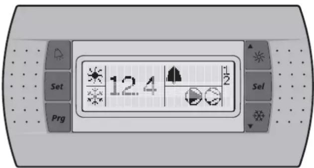
PcyHOK: INTeppeic ydaenHHoro nonb3oBateJI (KOMnEKT npno6peTaetc dononHntenbHO).
Ha npbte ynpabneHnmeIOCTc nedeYIOue KnaBn:
Функц,在,BblONHReMaN npn HaxaTIN NOJb3ObaTeIeM OHOI KJIaBUN INN IXKOMBHaZuIN,3aBNCIT OT COCTORHHIpybTa N YllpeBaHHbIMoment.
| KnaBVshn zhuΦpOBO nylIbTa yUrpAbeHnHa | KnaBVshn yDalaHnHOro mHTePfchEca | Главный диспeн | MEnIO ChTbIbAHn daTychOB | MEnIO blybopa napaMetpoB | MEnIO yctahOBkn napaMetpoB |
| Png: + | Png | -ОднokрathOE haxkaTHe: | B03BpAT | ОднokрathOE haxkaTHe: ВОЗБРТ | ОднokрathOE haxkaTHe: OTMEHа N BОЗВРТ |
| Sot: | Sot | HaxMVte n UdErjxHBaJIte 5 cekYnД: дяdoctуNA K PABOCHIM napametpAM - | ОднokрathOE haxkaTHe: Быбор napametpa UNI rpynnbl napametpoB | ОднokрathOE haxkaTHe: ПОДТВЕРЖДЕСЕ И ВОЗВРТ | |
| Png: + Sot: + Sot | HaxMVte n UdErjxHBaJIte 5 cekYnД: Png: + Sot: + NIM Одн pa3 haxMVte klnabNShy: Sot дяdoctуNA K napametpAM ПОЛь3OBATEЛЯ (noche BvoDA napona ПОЛь3OBATEЛЯ) | - | |||
| ▲▼ | ▲▼ | HaxMVte n UdErjxHBaJIte 5 cekYnД: ВКПLOUChENe/BvKIILOUChENe ChIINpePA В ржIMе harpeBA ОднOKрathOE haxkaTHe: праим DoCTyn К datчNK MeHIO ChITbIbAHn (bO /bO2/bO3) | ОднOKрathOE haxkaTHe: Быбор рpeblduyesso napaMetra daTychika | ОднOKрathOE haxkaTHe: Быбор рpeblduyesso napaMetra UNI rpynnbl napaMetpoB | ОднOKрathOE haxkaTHe: Увелочене знayеня |
| ▲▼ | ▲▼ | HaxMVte n UdErjxHBaJIte 5 cekYnД: ВКПLOUChENe/BvKIILOUChENe ChIINpePA В ржIMe OXJIaJcDEHn ОднOKрathOE haxkaTHe: праим DoCTyn К datчNK MeHIO ChITbIbAHn (bO /bO2/bO3) | ОднOKрathOE haxkaTHe: Быбор селduyesso napaMetra daTychika | ОднOKрathOE haxkaTHe: Быбор селduyesso napaMetra UNI rpynnbl napaMetpoB | ОднOKрathOE haxkaTHe: Уменихе знayеня |
| ▲▼ + Sot▼ | HaxMVte n UdErjxHBaJIte 5 cekYnД: сБрOC abarHNoI cnIRahlIzauCIn ВPyuchHyIO | - | |||
HnIkaTOpbIyIbTa ynpaBneHnIu ydaIeHHoro nHTepfceHa:
EcHn He HaxkMaTb KnaBnU, 3NaHeHne DaTuNka bO/6yDet OTo6paKaTbCn, noka ChOBa He 6yDet HxKata KnaBnua A nn Dn Bb6opa dpyrO npametpa (bO2nn bO3).
2YTo6bBepHyTbcB B rIaBBhBn DnCnne, HaxMnte KnaBnUy Pg|
EcIn BO Bpem HactpoiK MExy HaxaTneM KnaBn npoWIO 60nee 30 cekyn, OTo6paXaembI KOd nn 3NaueHne npaMeTp aHaHTe MNrta. Nocne eue 30 cekyn 6e3deCTBnnyLT ynpaBHeN ABOTMaTueCeKn Bo3BpaAaeTcB rIaNbHb IINCJIeN.
PeryunpoBka yCTaHOBOUHOro 3HaueHnTempeatypbI oxlaXdEHH
1 N3meHne npaMeTpa yCTaHOBOHOrO 3HaueHnO oxJaXDeHn
O pa6oHx npaMeTpax cm. B "PpocMoTp nI3MeHeHne npMbIX npaMeTpob" Ha cTpaHnue 8.
INPMMEAHME

Ecnn BkIIOHbI DBOHbIe ycTaHOBOUHbIe 3HaueHn (cm."Bb6Op DBOHbIX ycTaHOBOUHbIX 3HaueHn" Ha cTpaHnCe 13).
PerynipoBka yCTaHOBOUHOrO 3HaueHnra TempeaTypbI HarpeBa
1N3meHHeHyeCTaHOBOUHOrO3HaueHHaHapeBa-3.
O pa6oHx npametpax cm. B "PpocmoTp n3MeHeHne npMbIX npametpoB" Ha cTpaHnue 8.
ITPMME-LAHME

Ecnn BkIIOUeHb IBOHbIe yCTaHOBOUHbIe 3HaueHn (cm."Bb6Op IBOHbIX yCTaHOBOUHbIX 3HaueHn" Ha cTpaHnCe 13).
Iprocmot npHdopmaun o pa6ote yJIlepa
B cnncke pa6oHx npaMeTpoB MOxHO npocMoTpeTb cneDyUOuyu HnΦopMaunO paboTe nnepa:
bI: TemnepaTpa BoBHa Na BxOe B Hcnapntelb
bO2: TemnepaTypa BObHa Na BbIXOe n3 ncapuTeH
b03: npn akTNBn3HPOBaHHOM pexnme oxlanxdeHHa: TEMpepaTpya BObl Ha BXOe B KOHNcHcaTOP. Pn aKTNBn3HPOBaHHOM pexnme HarpeBa: TempepaTpya BObl Ha BXOe B INcapuTeIb.
C:06uee Bpempa6o7bBvacx Komnpceccopa 1
c/1: o6uee BpeMa pa6oTb b yacax KOMnpcecoppa 2
C 5: oobee Bpempa60bHaacocaBacax
PIMMEYAHME

NapametpbIb01,602n603TakKeMOxHO npocmOpTeB B"MeHIO CHTbIBAHNA DaTHNKOB". CM."PpOCMTo npametpoB"MeHIO CHTbIBAHNA daTHNKOB"" Ha cTpaHnue 8.
IInchtpkykun no c6pocy TaMepoB npaMeTPOB CIO, CIO H CIO CM. B "C6poc npedynpeKdHn"Ha cTpaHnue 10.
3To npambie napameTpbl, cm. pa3deJ "PpocmoTp n3MeHne npmbixnapameTpob"Ha cTpaHnue 8.
C6poc HnDnKaaun aBapnn
PnO6hApXeHn ABaPn npOnCxOuT cIeNyUoee:
cpaabaBaeT abapnHoe pene,
3aTogpaetcNINdNKaTop
Диспелн НаимаET Mгaть, NOpepeMeHNO OTO6paKaJ KOD abapnN TEmpepaTy BOdbl Ha BXOde.
Ha 3kpahe dncnne Moryr noBttbcra cneyuouie KoDbI abapin:
R: yka3bIBAeT Ha abapHIO, CBA3aHHyIO C MOpO3OYCTOHTNBOCTbHO
E: yka3bIbAeT Ha BblXoD n3 cTPOaTChKa NTC, n3MepraHIOeTe TMnepaTyP BObl Ha BXOe B nCnapHTelb
E2: yka3bIbAeT Ha BblOnd n3 CTPOAaTnKa NTC, n3MepraIOUero TempepaTyP BObl Ha BblXoJe n3 nCnapnten
E3: yka3bIbaet Ha To, TTo neperopen npedoxpaHnteIb NeHTOCHoro HArpeBaTeIaNcapTeIa (F4); npo3o7na Ow6Ka, CBA3aHHaC npepa3npoBko; NII YTO BO3HNKNa HeNCpabHocTb Ha NlaTe BXOIOB/BbIXOIOB (A2P).

Ecnn qnilnep ochaueh 3auntoiOT 3amep3aHnna, HactoTebHo peKOMeHdyetc yctahOBHTb lamny dNCTAHNOHHO nHdNKauu ABapn (H3P) (cm. npinaraemyo K uinnepy 3neKTpnueckkyo cxemy). Blaorapn 3TOI nAMne neperopanhe npedoxpaHNTen JHeTOUHoro HarpeBaTeN hcnapnten (F4) MOxHO 6ydet 0bnapyKnB 6bictpee, YTO NO3BOJNT N36ExaTa 3amep3aHnno KOHTya B xOLOHoe Bpemr rOda.
EH5: yka3bIbaeT Ha cNIuKOM BbICOKOE HApJxKeHne NtAHINB 3TOM cnyae 06paTntecb K aTTecTOBaHHOMy 3NEKTpIKy.
EL: yka3bIbAeT Ha OwH6ky PnTaHn (HapnpMep, nomexn) B 3Tom Cnyae 06paTntecb K aTTectObaHHOMy 3JIeKTPnKy.
EL2: yka3bIbaet Ha OwH6ky PtHaHH (HapnpMep, nomexn) B 3tOM cnyae 6paTntecb K aTTectOBAHHOMy 3JIeKTPNkY.
ELS: yka3bIbaET Ha cNIuKOM Hn3Koe HAnpJxHHe NITaHIN B 3TOM cnyae o6paNTecb K aTTecTOBaHHOMY 3NeKTpIKy.
EPb: yka3bIbAeT Ha BbIXoN 3 CTPOM MKNPCXEmbl 3JIeKTPoHHO-nepenporpamMmuPyemOIO NOCTOHHNO nAMrtn (EEPROM) Ha nIate nyIbTa ynpabEnnBHyTpNIHIIpepa
EP: yka3bIbaeT Ha BbIXoN 3 CTPO MKNPCXEmbl 3JIeKTPoHHO-nepenporpamMpyEmo NocToHHO nAMrtn (EEPROM) Ha nIate nyIbTa ynpaBneHnBHyTpN HJIepa
FL: yka3bIbaeT Ha oTCyTCTBHe DoCTaTOHORo npOTOKA BObl IINBO TceHHe 15 cekyHn Nocne 3anycka Hacoca, IN60 B TeHHe 5 cekyHn Nocne BKIOUeHn KOMnPecCopa, IN60 Ha CpaBaTbIbAHne 3aUNrHb HACoca No MaKcIMAbHOMy TOKY
HP: yka3bIbaeHaTo, TTO cpa6oTano pene BblcOKoro DaBnEHHa, pene TEnIOBo 3aunTbHa BblXOde KOMPecccopa NIN 3aUNTA 3NEKtpoDBnraTeN KOMPecccopa No MAKCmAlbHOMy TOky, IIn60 Ha To, YTO BbiJen n3 CTOAHTNK, IN3MepRIOuN TeMnepaTpy OkpyxauOe Cpebl
FL+HP: yka3bIaET Ha Han6Oone BepoTHyO ow6ky RPP nnHa neperopeBm npdoxpaHntelb F4
Lp: yka3bIbAeT h cpa6aTaBbAHne peJe Hn3KOro daBHeHH
E: yka3bIbaET Ha OIN6ky CBA3n INTEpeIca ydaJIeHHoro NOJb3OBATeTn
Offline: ow6ka cBra3n uDpOBO rnybTa ynpaBHeHr YIInpeA HHTepEeCA ydaENHOro nonb3OBaTeRa NqTBepDnTe npabNtBocTb Bb6opa Koda napaMeTpHa23. No yMOnuAHIO dONXHO 6bTb yCTaHOBHeO 3NaeHne O. NqTBepDnTe IcnpaBLeHne yCTaHOBKn B COOTBeTcBm C INCTpyKUmei NO MONTaxy HTepFeCa ydaENHOro nNoB3OBaTeRa EKRUMCA.
PIMMEAHHE

Ecnnnonepemehno Mmraot Kcbi abapnn FL n H I, TO npnuHoi noaun abapnHoro cInHa nBaepoTHee BCero ABnIeTc npabTaBbAHne yCTpOuCTBa 3auNTbI OT nepepa3npOBKn nn npeperopanHe npedoxpaHnten JENTOCHoro HarpeBaTeN HCnapnte (F4).
YTo6bI c6pocntb HnDnKaun aBapnn, Heo6xoJMo BblONHHTb CNeDyIOUne DeECTBNA:
1 HanTe npuHny ocTaHOBKn uNIIepa uYcTaHnTe ee.
Cm. pa3dien "Bo3MOXHbIe HeINcnpaBHOCTn n cnocO6blnx yctpaHENHa cTpaHnue 16.
2 EcnHa dncnnee noBnncb KoIbI abapnn R I,FL,HP I nnnp LP1, c6pocbTe INHnKaunIO abapnn BpyHyIO. Dn3 3TOO OHOBPemHeHO HAKMITE KOmBnHaUNIO KnaBn clear 4n u ydepKNaBte nX OKOno 5cekyHd.
Bo Bcex dpynx cnyaax Hdkaun aBapnn c6pocntca ABTOMATUeCKN.
Iocne c6poca HnDkaun abapnn KOD Own6kn n HnDkaTOp Ncye3nyt C 3kpapa Dncnpe. PynbT ynpabNeHnBepHeTcB HopMaNbHoe pa6ooyee coCTOHNe n HaHTet OTo6paKaTaTe TMnepaTyP BObl Ha BxOJe.
C6poc npedynpekdeni
Bo Bpemn HopmaIbHOB pa60TbI qnnepa nncneN nyIbTa ynpabLeHNO MoKET Haatb MrrA, nonepMeHHO OTo6paKaTeMnepaTyPOBHO BAxOe IN CNDyUoIN KO npDynpexDeHnR:
HcI: yka3bBAeT Ha Heo6xOIMOCb npOBedeHnayTexHneCKoro 06cnyKuBaHHaN KOMPpeccopa 1: 6ouaHapa6oTKa KomPpeccopa 1 B vacax (pa6oHn npaMeTp c I) npebbcunna 3aDaHHoe TaMepy noporOBoE 3HaueHne nnoaHn CnHaJa O Heo6xoDnMOCTn npOBedeHnay TexHneCKoro 06cnyKuBaHHaN (npaMeTp noIb3oBaTeJIc I-
Hc2: yka3bIbaeT Ha Heo6xOdMocTb npOBedeHnA TeXHmEeCKOrO 06CnyKuBaHnN KOMnPeeCoppa 2: 06uaA Hapa6OtKa KOMPeeCoppa 2 B vacax (pa6Och napaMeTp c11) npEBbICnna 3aDaHHoe TaMEpy nopOROBoe 3HaueHne DnN POnaHi CnHana O Heo6xOdMocTn npOBedeHnTeXHmEeCKOrO 06CnyKuBaHnN (napaMeTp nonb3oBaTeJIc14)
406bIc6pocntb npedynpejxdeHne O Heo6xoJIMOCTn npoBeHn texHueckoro 0cbnyKuBaHn Hc1nn Hc2, Heo6xoJMO BblONHTb CNeDyUOune DeiCTBn:
1 NocmotpuTe 3naueHne npaMeTpca I Bpempa60tbI B yacax kompeccopa 1 nn C / I Bpempa60tbI B yacax kompeccopa 2.
O pa6oHx npametpax CM. B "PpocmOpTn n3MeHeHne npMbIX npametpoB" Ha cTpaHnue 8.
2 Ecn 3naeHne npametpa c t nn c t o6paKaaeTc, OHOBpeMeHo haxMnte KnaBnU H a 5 cekyHd. 3naeHne TaImepa 6ydt yctaHO bHe Ho Ha Q, a npdeynpeJxDeHne c6poWeHo.
PIMMEAHME

Pocne c6poca TaHmepOB He 3a6ydbTe npoBeCTn Heo6xOdMoe TexHmueCKOE 0cClykuaHne.
Kpome c6poca TaHmepOB c10 n c11 TaKxe BO3MOxHO c6pocntb TaHmep c15 (BpeMpa60tb HAcOCA B HaCaX) TaKIM Xe 6pa3OM.
DononHnteBhIe BO3MOXHOCTN UΦPOBOrO nylbTa ynpabJIeHH
B 3TOM pa3dene npedctabneH o6uH o63Op pa6OuNx npametpoB n npametpoNb3OBaTeJI, KOtObIe N3BOJnE TmEHrT bNyIbTynpaBHeH. B cNeDyIOUeM pa3dene npINBOJrTcB CBeJeHnO hAcTPOKe n KOHpIpyPpOBaHn YIIInepoB c NMOUHO 3TNX npametpoB.
O63op npaMeTpOB npAByN NOJb3OBaTeJbCKNX npaMeTpOB
YTo6blnOyUHTb DocTyN K CnIcKcy pa6OuNx npaMeTpOB, HaxMnte KnaBmUy 5ef; n ydePkUbaIte ee oKOIO 5 cekyHd. TaKke cm. pa3den "PpocMOTp N m3MeHHe NpAmbix npaMeTpOB" Ha cTpaHnue 8.
BbI6Op DBOHbIx yCTaHOBOUHbIX 3NaueHn
Iapametpbnolb3oBaTeaPQ9(Bbl6op n3MeHemoro cnpboROBBOda S7S) n P34(Bbl6op n3MeHemoro cnpboROBBOda S9S)MOXHO nCnONb3oBaTb dnn pncBOeHHN cyHKUIN DBOHBIXyCTAHOBOHTb 3haueHm S7S nn S9S.
Ectb DBe 3 pa3HbIe cyHKcIy npaBHeHn Ia 2 n3MeHn UΦpObbl BBOIOB (S7S n S9S):
P09: BB6op 3MmHReMOrO uΦpOBOro BBOda S7S
0=He mMeet yHKuM
9=ntaHnOHoe ynpabHeHne oxnaJeHem/HarpeBOM
13=DBOHyIe ydaIeHHbIe ycTaHOBOUHbIe 3HaYeHnA
P34: nAmehembI Bbl6op IJI BBOda UΦpOBoBx daHbX S9S
0=He mMeet ΦyHKUH
13=ДВОИньеудалeHHbe yCTaHOBOчьпeЗHAчEHnA
23=ДИСТАнCUHNOHHOE BKNIOUCHENBbIKIQUHEnE
EcIn BkNoHcyBbIy DBoHbIye yTaHOBOHyBe 3HaeyHn, AKnBnPoBaHo nepBoe yCTaHOBOHoe 3HaeyHne (rO I yCTaHOBOHoe 3HaeyHne oxJaXdEHHn nn rO3 yCTaHOBOHoe 3HaeyHne HarpBa B 3aBNCIMoCTn OT pexnMa pa60tBuNlpe).
EcIn BbIKIouHeHb IBOHbIe yCTaHOOchBIE 3HaueHnA, AKTNIBPOBAHO BTOpoe yCTaHOBOOHoe 3HaueHne (r² i yCTaHOBOOHoe 3HaueHne OXNaXdEHHN2 uIN r² yCTaHOOCHOE 3HaueHne HarpBa 2 B 3abCmocnTOn pexkima pa6oTbIynnpepa).
O napameTpax nonb30BaTeTn CM. B "PpocMToP n3MeHeHne nnonb30BaTeBcknx npameTpob" Ha cTpaHnue 12.
Блokировka knaBnatapyi npIbTa ynpaBneHn
Iocne toro, kaknapaemtpy nonb3oBateJH 6ydt 3aHaHO 3haHeHne , c nOMOsbnoNyIbTa ynpaBneHn HEnb3a 6ydt 0baaatbcK CNeDyUOIM DOnONHInTeNbHbIM BO3MOXHOCTAM:
I3MEHeHne pa6OHH npaMeTPOB n npaMeTPOB NOb3OBaTeN (NX 3HaueHn MOxHO 6yDet NpOCMOrpeTb, HO HeJIb3A I3MEHHTb),
c6poc TaMepoB.
BKNIOUOHeHNE/BbIKIOUeHNE YINNepa BpeXnme OxnaJDeHnHaHarpBa
06paatabca K BblwepepeueeHbbIM DOnONHTenBbIM BO3MOXHOCTAM C NOMOIOyNtTa ynpaBHeHnMoKHO 6yDet TOrda, KOrda napameTpnoIb3oBaTeT H6yDet npCBOeHO 3aueHne I.
IIN3MeHHeN 3HaHeHnnapaMeTpa nOb3oBaTeN H09 c I Ha O DeInCTByIte 06blHybIM 06pa3OM NO IN3MeHHeNIO npaMeTpOB INb3oBaTeN C 06blHybIM napoEm "22". CM. "PpocMoTp IN3MeHHeN IOBb3oBaTeNbcknx npaMeTpOB" Ha cTpaHnue 12.
IIN3MeHHeN3HaueHnnapaMeTpa NOnb3OBaTeNHOHa I DeiCTByIte O6bIyHbIM O6pa3OM NO IN3MeHHeNIO npaMeTpOB INb3OBaTeNr CO CneuaJIbHbIM napoEM " /". CM. "PpocMToP IN3MeHHeNIE NOnb3OBaTeNbCKNX npaMeTpOB" Ha cTpaHnue 12.
CoeHHeHc c cTeMoB BMS no npotoKoJy modbus
YcTaHOBnPnpO6peTaembI DOnONHITeBHO KOMNJIeKT C aDpeCHO KapToE KAC10C, BblCMoKTe ynpaBnTb HINLepom npn NOMOu cNCTeMbI ynpaBLeHnOBOpyIDoBaHEm 3daHn INn C NOMOuBO cNCTeMbI dncNetUePKoRTO ynpaBHeHnNo npoTOKny Modbus.
06ee onncanme Modbus
Apechar KapTa pa6oTaet no npToKoJy Modbus.
Pa3JInuHbIe yacTn KOMmyHkauoHHoCetN
KOMMyHKaIOHnHaCeTb COCTOIT N3 DByx OCHOBbIX YaCTeI:
CnCTembl npablenHIO6OpyObaHem 3daHIN (BMS) nnn CnCTembl DCNCTepeckoro npablenHIN
Ynllepa nn HeckoBkX YnllepOB.
CnCTema BMS nIu npyra CnCTema DnCneTepckoro ynpaBHeHnO cUyIeCTbIeT CB83b CnnIePamN cep3 aDpeChHyIO KapTy.
UnpaBHeHne KOMMyHnKaUHmnpoCXoDHT BpaMKax nocJeobatEnbHO onpaWuBaEMO CTpyKTypbl "rIabHbI-BTOPOCTeHbI",rIe DncNcTeUpeckaBMS RbJIeTcR rIaBHOn,a aIpeChBe INaTb -BTOPOCTeHbIMn.
Hnep HdHTnHnpyetc CNTeMoN NocpeCTBOM npncBOEHn EMy aDpeca B cetn Modbus. AApec YnIepa MOxHO BBecTN BO BpemK KOHnpuropoBaHN BMS.
Ba3a DaHHbIX nepemehbix dna KaJdoRo Ynllepa, 060pyoDBAHHO apechoH nIaTOn ABnEeTc DnI NOCTabuNka DnCneTepckO cnCTembl TocKo OTcHeta Modbus, NcxOJa n3 KOTOpoi nepemehbIM Heo6XoIMMo Ha3HaHTb NDOxOJaUne 3HaHeHn.
IpeMeHHbIe MOryT npOHTbIBaTbCn n/nn 3aNNcBtBaTcBc CpeCTBaMn CNTEmbl DnCneTHePCKoro ynpabJIeHn. Bo3MOxHOCTb YTeHn Nn YTeHn/3aNcN nepeMeHHbIX 3aBNCIT OT NOkIOHeHHORo YInnepa /nN ot NcNoIb3yeMoI nporpaMMbl.
- EcnncTeMa nncnTepckoro ynpaBneHn npncBaNAe3naehne nepemehno, KOtopa OTkpbTA TOJbKO dJIyTeHnKOMaHaDa BOO6ue He 6yDet BbINOnHeHa.
-
Iepemehhie, OTCyTCTBIOUne B CnCTMe YINNepa c apeoh KAPToH 3aTpe6oBaHHbIe CnCTMeOH ynpabNeHn, OTnpabJIHOc Tc apechoH KApTbI B CnCTEmy ynpabHeHn C HynEbIM 3HaueHHeM. CnCTema dncntYepcKOrO ynpabHeHn DoJxHa npabJIbHO INx 06pa6oTaTb.
-
Ecnn CnCTema DnCnTeUepCKoTo ynpaBneHnNONbTaTc3aNcapTa 3NaHeHne npaMeTpBa BHe dOnyctmblx npeDeIOB3NaHeHn, To TaKaA 3AnCb 6yDc TnpOyuSha.
Obne CBeHnO npToKone Modbus
PpotoKoN Modcon Modbus, BHepeHHbB aapeChoi nIate, COOTBeTCTBye CoepKIMOMy CneDyIOUero DOkymeHTa:
IpoToKoN Modicon Modbus
PykoBOcTBO no pnmHeHHIO
IIOHb 1996 r., PI-MBUS-300 peJ. J
BHepeHbI npToKoM Modbus, npHaJnEaKIT K Tny npToKoNob
dYdaenHbIX TepMHaJIbHbIX 6NoKOB Ha OCHOBE BpEmEH
nepeDaun CIMBOJOB. B KOhFurpaUIN NcnoJb3yeTcA
MHorokaHbH aFyHKuIe cTe RS485.ADPEC,OTnpaBJeHHb
BHTPn NaKeTa npToKoMa Modbus, 6baaetcK 6NoKy Ynnnepa.
BHepeHb HacTpoKn RS485 nI npToKoJa Modbus
KoHnpyaRr RS485 npmehreTc neyioom 6pa30m
CkopoocTbB6oJax:9600
CTonobBb6nT:2
YeTHoCTb: Het
BHepeHHbIe KOMaHdbI npToKoJa Modbus
BHepeHHbI KOMaHdbI nporpaMMbI TaKOBbl:
| KoMaHnda Modbus 3NaueHne ДяЗametok | ||
| 01чNTbIbAHnEcoCTOHNIA3MeEBNkA | CHTbIbAHnEζΦpOBxBnipemEHhIX | ИЗБLEЧЕНЕ TEKУСEROCOCTOHRN(AВКЛЮЧЕН/OВВКЛЮЧЕН)ДЯг rуППьILOTNHECKNX 3MeEBNkOBIIIлДи ДИСКРТHERО BVOДA |
| 02чNTbIbAHnEcoCTOHRNIBXODa | CHTbIbAHnEζΦpOBxBnipemEHhIX | ИЗБLECHENIE TEKUÇEOCOCTOHRN(AВКЛЮЧЕHOBvBvKЛЮCHEHOДЯг rуППьILOTNHECKNX 3MeEBNkOBIIIлДи ДИСКРТHERO BVOДA |
| 03чNTbIbAHnEPERiCTPatoPobUydepxKaH | CHTbIbAHnEahAnorTOBxBnipemEHhIX | ПОЛУСАТ TEKУСЕ БИнAPhoe3HAChENIEВ OДФOMIIППБЕPERiCTPAX xpaHEnHЯДaHHbIX |
| 04чNTbIbAHnEPERiCTPatoPobBXODa | CHTbIbAHnEahAnorTOBxBnipemEHhIX | ПОЛУСАТ TEKUÇEE BИнAPhoe3HAChENIEВ OДФOMIIПБЕPERiCTPAX xpaHEnHЯДaHHbIX |
| 05prINHyDITeNBHeOIM3MeENHnEOTdElbHOrO3MeEBNkA | 3aInscOTdElbHbIXπΦpOBxBnipemEHhIX | ПОИΥДITeNBHeO IM3MENHnECoCTOHRN OТДeЛbHOrO3MeEBNk(AВКЛЮCHEHO/OTKЛIOUChEO) |
| 06preJyCTaHOBKaOTdElbHOrOpereiCTPatoP | 3aInscOTdElbHbIXahAnorTOBxBnipemEHhIX | ПОМЕSUHNE KOHKePETHORO6HapHORO 3HaYEHnB PERiCTPBePemEHORO xpaHEnHЯMHΦoPmauIINHΦoPmauIIN |
| 15prINHyDITeNBHeOIM3MeENHnEHECKOLbKnx3MeEBNkoB | 3aInscOTcpeRINzΦpOBxBnipemEHhIX | ПОИΥДITeNBHaI 3aInscNPOSLEDAOBATEbHbIX IONGHECKNX3MeEBNkoBДЯng NOsLEDAUQUSEYUCTaHOBKn COSTOHRN BKNJIQUHcO H |
| 16preJyCTaHOBKaHECKOLbKnxperiCTPatoPob | 3aInscOTcpeRINaHANoTobHbIXnipemEHhIX | ПОМЕSUHNE KOHKePETHbIXDBOINbIX 3HauchENI B cepmIONoSLEDAOBATEbHbIX periCTPBOXPAHENHЯДaHHbIX |
O6paTnTe BnHaHne
B CBA3N C 60JIbIIM pa3Hoo6pa3nem YIJIIEPOBC yCTaHOBHeHHo apechoH KAPToH He Deaetcpa3JINm MEXy BXOJHBIMN NpeMeHHbIMN (co CTaTYCOM TOnbKO dIy TEHn) IN BbIXOJhbIMN NpeMeHHbIMN (co CTaTYCOM dIy TEHn/3aIncn). IIO3TOMy CBeDeHn 6a3bl DaHHbx n ee ynpabJIeHHa 3aBNCrOT CNTEmbl DInCneTepckoro ynpabJIeHHa.
B Cb3n C 06mXapaKTePOM CNTembl aDpeCha KapTa OTBeHaet OINHAKOBO Ha pa3NHyIbe KOMaHDb Modbus.
PpeDCTaBHeHne DaHHbIX npToKoNa Modbus
LindpobBle
BceuPpObIe DaHHbIe KOdpyIOTc EINHnHbIM 6NTOM
"0"ДЯнВыКЛ
"1"ДЯВКЛ
Bce uDpoBbI nepeMeHHbI npnncaHbI K 6ntam nocneobatehblx perncTpoB, y KaKdoro I3 KOtOpbix ectb
60Jee MnaDn anpec nepemehho, npnncaHHbK MeHee 3NaHmomy 6nty
60Jee cTapwI aDpec nepemehHO, npnncanHbK 60Jee 3HaHMMoy 6uTy
AHAANOROBbie INHTerpaIbHbIe daHHbIe
AHaIorOBoE nHTERpaIbHoe 3NaueHne npedctaBHeHO 16-Tn pa3pIbHM CIOBOM B IBOuHOM OTo6paKeHN. B KaKdOM perIcTpe nepBbI 6aHT coepkNT CTapUne pa3pIbI, a BTOPOI 6aIT -MnaDnue.
AHaIorOBbIe 3HaYeHnI npEcdTaBHeHbI KpaTHO DecrTn: HApIMep,3HaYeHne 10,0 nepeJaetcKaK 0064h=100d HApIMep,3HaYeHne-10,0 nepeJaetcKaF FF9Ch=-100d
HHTerpaJIbHbIe nepemehhble nepeaOTcC NIOB3OBAHnEM 3ΦΦeKTHBHO 3HaueHHaHnPIMep, 3HaueHne 100 nepedaetcKaK 0064h=100d
Apehna Kapta B3amOmeJCTByET C perncTpAmn, OINH n3 KOtopbIX DOJXKeH pacCMatPnBaTbcra KAK 16-Tn pa3pndhbl.
EcnBMS nIcTeMa dncnTepckoro ynpabEnHn bItaetC BBeCTn 3NaueHne npametpa, KOtOpoe BbIXoNT 3a paMKN donyctmOrO dnaana0Ha, 3anCb 6ydet npOnyuSha.
BhepeHHbIKoDOWn6Kn
KoI INTEpnpetaaModbus NonoXeHne
1 He donyctmam yHKnna Coo6eHne He nopejxnaeTc nI np3e6yemoe KOINecTBO nepeMeHHbIX npBbIaet donyctmbln peDeI (dlnHa 20)
OnpeJeHne Hacpoek BMS
AknBaun npToKoJa Modbus
IpoTOKoJ Modbus akTNBnpyETcR nyTEM yCTaHOBKn npaMeTp aH23 B 3haeHne I.
O napametpax nonb3OBaTeIa CM. B "PpocMOTn n3MeHeHne nnonb3OBaTeJIbcknx npamETpoB" Ha cTpaHnce 12.
3aandaHne nocleIOBaTeIbHOrO aIpeca HJIIEpa
YTo6bl onpeDenntb yHnKaIbHbI NOcNEoBaTeIbHbI aDpec KaKdoRTO uIInepa dna cooocheHH c CnCTeMOI duCneTepckoro ynpablenHH,3aaiTe napametp H 10.
O npametpax nonb3OBateJn CM. B "PpocmOpT n 3MeHeHne nonb3OBaTeJIbcknx npametpoB" Ha ctpaHnce 12.
Ba3a daHHbIX nepemehHbIX
CnCTema ynpablenen 3daHem mnn CNTema nncneTepckoro
ynpablenen u nnlep coo6zauOTc pyTeM o6MeHa
fMKCNPOBAHHbIM Ha60pOM nepeMeHHbIX, KOtOpBIE TaKke
Ha3bIBaIOCTc HomepaMn aDpecoB. Daanee Bbl HaNdTe
Heo6xOdmbie cBeDeHn O cnffpoBbIX, ZelOuNCleHHbx
n aHaanorOBBX nepeMeHHbIX, KOtOpBIE BMS nncTeMa
nncneTepckcKO r npablenen MOXET CHTbBaTb Nn 3aNNcbBaTb
Ha aDpeChyIO KapTy nnIepa.
Дяаадрсов ДЯ BCEX npambyи NOIb3OBaTeNbcknx NapamETPOB CM. pa3dEN "O63Op napamETPOB npambyи NOIb3OBaTeNbcknx napamETPOB" Ha CTpaHnue 10.
063opBceX nepemeHHbIX,HE ABnIOUxxCn pRMBIMNINI NOb3OBATEJIbCKMIM
Pn3Hak HncnpaBHOCTn 2:Ynnep He 3anyckaetc, Ho CBeToNDMuraT
P a3Mep OTBepCTnCETKN DOJXeH 6bITb He 6oJee 1 MM.
YTNIN3aun
Demontax 6noka, ydaeneHne xonoNbHoro areHTa, macna n npyrnx qacteI dJXKbl npBOIDtbcra B COOTBcTCTBIM C MecTHbIM n o6ueroCyapctBeHHbIM 3aKOHDAteBCTBOM.
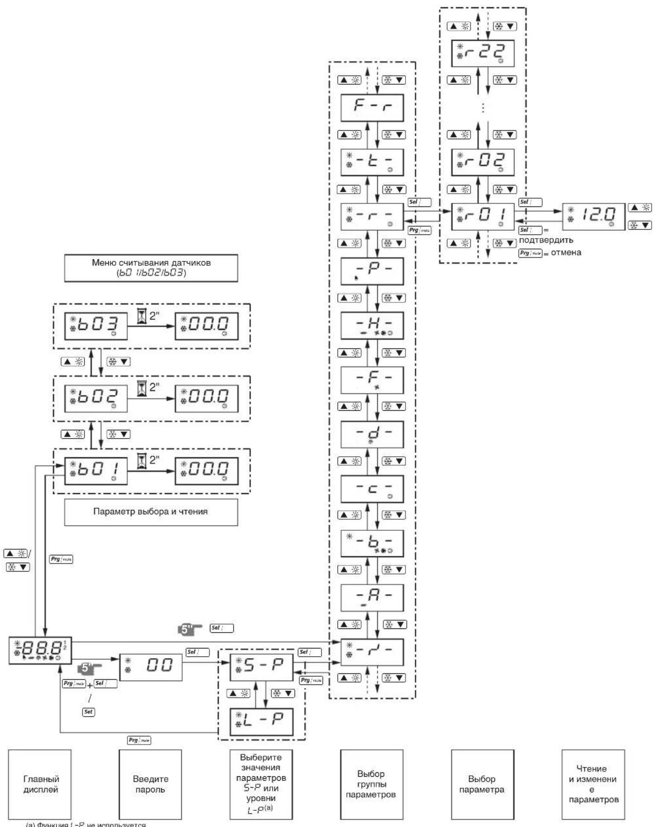
(a)ΦyHKUaL-PHeHcNcNoB3ayETCA.

- Packaged water-cooled water chillers
- CONTENTS Page
- INTRODUCTION
- Technical specifications(1)
- Electrical specifications(1)
- DESCRIPTION
- Figure - Main components
- Function of the main components
- Safety devices
- Internal wiring - Parts table
- BEFORE OPERATION
- Checks before initial start-up
- Water supply
- General recommendations
- OPERATION
- Digital controller
- User interface
- Direct and user parameters
- Working with the units
- Switching the unit on
- Switching the unit off
- How to consult and modify the direct parameters
- How to consult the "sensor readout menu" parameters
- Adjusting the cooling temperature setpoint
- Adjusting the heating temperature setpoint
- Consulting actual operational information
- Resetting alarms
- Resetting warnings
- Advanced features of the digital controller
- Overview of the direct and user parameters
- Defining the heating temperature differential
- Defining the measurement unit
- Defining the time delay between unit and pump shutdown
- Defining the timer threshold for maintenance warning
- Selecting local or remote cool/heat control
- Selecting local or remote on/off control
- Selecting dual setpoint control
- Locking the controller keyboard
- BMS CONNECTION MODBUS
- General description of Modbus
- Different parts of the communication network
- General information about the Modbus protocol
- Implemented RS485 communication settings for the Modbus protocol
- Implemented commands for the Modbus protocol
- Note that:
- Data representation of the Modbus protocol
- Implemented error code
- Code Modbus interpretation Condition
- Defining the BMS setting
- Activating the Modbus protocol
- Defining the unit's serial address
- Variables database
- TROUBLESHOOTING
- MAINTENANCE
- Important information regarding the refrigerant used
- Maintenance activities
- Disposal requirements
- STORINGSOPSPORING
- Pouiogeic erikovwiac RS485 nou xpnoioivvta iat to nptoKoA Modbus
- Bao n eTa6aTowv 8oov
- 3aunTHbIe ycTpOcTBA
- BHytpenHn npoBODka - IpeueHb 0603Haehn 3JEMENTOB 3NeKtpnuecknx CXEM
- IpeepaHauanompa6oTbI
- YTO HxKHO npOBepntb nepe npBbIM 3anyckOM
- 13neKtpoPBOKa
- PpeoxaHTeNn 3aunTHbIe yctpoiCTBa
- 33a3eMJIeHne
- BHytpenHnA 3neKtpponpoBOKa
- Kpenex
- MexaHnueckne noBpeKdennr
- Teuka xlaaareHtA
- 8YTeKaMaCna
- HanpaxeHne 3neKtponTahn
- IopaaBoDb
- ObepekekomendaH
- UnpaBJIeHne pa6oToI qHIIpepa
- UΦpOBoI npIbT ynpaBneHnA
- Inhteppeic noJb3ObaTea
- Iprocmot npHdopmaun o pa6ote yJIlepa
- C6poc HnDnKaaun aBapnn
- C6poc npedynpekdeni
- PIMMEAHME
- DononHnteBhIe BO3MOXHOCTN UΦPOBOrO nylbTa ynpabJIeHH
- O63op npaMeTpOB npAByN NOJb3OBaTeJbCKNX npaMeTpOB
- BbI6Op DBOHbIx yCTaHOBOUHbIX 3NaueHn
- Блokировka knaBnatapyi npIbTa ynpaBneHn
- CoeHHeHc c cTeMoB BMS no npotoKoJy modbus
- 06ee onncanme Modbus
- Pa3JInuHbIe yacTn KOMmyHkauoHHoCetN
- Obne CBeHnO npToKone Modbus
- BHepeHb HacTpoKn RS485 nI npToKoJa Modbus
- BHepeHHbIe KOMaHdbI npToKoJa Modbus
- O6paTnTe BnHaHne
- PpeDCTaBHeHne DaHHbIX npToKoNa Modbus
- BhepeHHbIKoDOWn6Kn
- KoI INTEpnpetaaModbus NonoXeHne
- OnpeJeHne Hacpoek BMS
- AknBaun npToKoJa Modbus
- 3aandaHne nocleIOBaTeIbHOrO aIpeca HJIIEpa
- Ba3a daHHbIX nepemehHbIX
- YTNIN3aun
Brand : DAIKIN
Model : EWWQ025KBW1N
Category : Water pump