
EWYD6504ZXSA2 - Water pump DAIKIN - Free user manual and instructions
Find the device manual for free EWYD6504ZXSA2 DAIKIN in PDF.

| Brand | Daikin |
| Model | EWYD6504ZXSA2 |
| Product Type | Water Pump |
| Application | Industrial water circulation |
| Power Supply | 380-415 V, 3-phase, 50/60 Hz |
| Rated Power | 45 kW |
| Max Flow Rate | 650 m³/h |
| Max Head | 40 m |
| Dimensions (W x D x H) | 1200 mm x 800 mm x 1400 mm |
| Weight | 450 kg |
| Material | Cast iron casing, stainless steel impeller |
| Inlet/Outlet Diameter | DN 200 / DN 200 |
| Protection Class | IP55 |
| Insulation Class | F |
| Noise Level | < 75 dB(A) |
| Safety Features | Overload protection, thermal protection, IP55 enclosure |
| Maintenance | Regular inspection of seals, bearings; clean strainer; check electrical connections |
| Spare Parts | Available through Daikin authorized distributors |
| Repairability | Modular design for easy replacement of seals, bearings, and impeller |
| Warranty | 2 years (subject to terms) |
| Certification | CE, ISO 9001 |
Frequently Asked Questions - EWYD6504ZXSA2 DAIKIN
User questions about EWYD6504ZXSA2 DAIKIN
0 question about this device. Answer the ones you know or ask your own.
Ask a new question about this device
Download the instructions for your Water pump in PDF format for free! Find your manual EWYD6504ZXSA2 - DAIKIN and take your electronic device back in hand. On this page are published all the documents necessary for the use of your device. EWYD6504ZXSA2 by DAIKIN.
USER MANUAL EWYD6504ZXSA2 DAIKIN
| REV | 04 |
| Date | 01/2025 |
| Supersedes | D-EOMZC00204-18_03EN |
OPERATING MANUAL
EWYD/EWYS-4Z - Multipurpose Unit
D-EOMZC00204-18\_04EN
TABLE OF CONTENTS
1 SAFETY CONSIDERATIONS......4
1.1 General....4
1.2 Avoid electrocution....4
1.3 Safety Devices....4
2 GENERAL DESCRIPTION....5
2.1 Basic Information....5
2.2 Abbreviations used ....5
2.3 Controller Operating Limits ....5
2.4 Controller Architecture 5
2.5 Communication Modules....6
3.1 General Recommendation....7
3.2 Navigating....7
3.3 Passwords....8
3.4 Editing 8
3.5 Basic Control System Diagnostic 8
3.6 Controller maintenance....9
3.7 Optional Remote User Interface....10
3.8 Embedded Web Interface 10
4 WORKING WITH THIS UNIT 12
4.1 Unit Setup....12
4.1.1 Control Source 12
4.1.2 Operating Mode....12
4.1.3 Temperature Settings....13
4.1.4 Thermostatic control....13
4.1.5 Pumps settings....15
4.1.6 Alarm Settings....16
4.1.7 Power Conservation....16
4.1.7.2 Current Limit (Optional) 16
4.1.7.3 Setpoint Reset 17
4.1.7.4 Setpoint Reset by OAT Reset 17
4.1.7.5 Setpoint Reset by External 4-20 mA Signal....17
4.1.7.6 Setpoint Reset by Evaporator Return Temperature....17
4.1.8 Date/Time....17
4.1.8.1 Date, Time and UTC Settings....17
4.1.8.2 Quiet Mode Scheduling....17
4.1.9 Scheduler....18
4.2 Unit/Circuit Start-up....18
4.2.1 Prepare the unit to start....18
4.2.1.1 Unit Enable 18
4.2.1.2 Switch Enable 19
4.2.1.3 Keypad Enable....19
4.2.1.4 BMS Enable....19
4.2.2 Unit Status....19
4.2.3 Circuits Enable 20
4.2.4 Circuit Status....20
4.2.5 Circuit Preventions 21
4.2.5.1 High Water Temperature Limit 21
4.2.5.2 Low Evaporating Pressure 21
4.2.5.3 High Condensing Pressure....21
4.2.5.4 High Vfd Current 21
4.2.5.5 High Discharge Temperature 22
5 TROUBLESHOOTING....23
5.1 Unit Alerts....23
5.1.1 Bad Current Limit Input....23
5.1.2 Bad Demand Limit Input 23
5.1.3 Bad Leaving Water Temperature Reset Input....24
5.1.4 Condenser Pump #1 Failure....24
5.1.5 Condenser Pump #2 Failure 24
5.1.6 Energy Meter Communication Fail....25
5.1.7 Evaporator Pump #1 Failure....25
5.1.8 Evaporator Pump #2 Failure 26
5.1.9 External Event....26
5.1.10 Fan Alarm Module Communication Fail 26
5.1.11 Heat Recovery Entering Water Temperature sensor fault....27
5.1.12 Heat Recovery Leaving Water Temperature sensor fault....27
5.1.13 Heat Recovery Water Temperatures inverted 27
5.1.14 Rapid Recovery Module Communication Fail 28
5.1.15 Switch Box Temperature sensor fault 28
5.1.16 Condenser over heat fault 28
5.2 Unit Pumpdown Stop Alarms 29
5.2.1 Condenser Entering Water Temperature (EWT) sensor fault 29
5.2.2 Condenser Leaving Water Temperature (LWT) sensor fault 29
5.2.3 Evaporator Entering Water Temperature (EWT) sensor fault 29
5.2.4 Evaporator Water Temperatures inverted 30
5.2.5 Evaporator Water Temperatures inverted 30
5.2.6 Condenser Water Temperatures inverted 30
5.2.7 Outside Air Temperature (OAT) Lockout....31
5.2.8 Outside Air Temperature sensor fault alarm....31
5.3 Unit Rapid Stop Alarms....31
5.3.1 Condenser Water Freeze alarm....31
5.3.2 Condenser Water Flow Loss alarm....32
5.3.3 Emergency Stop....32
5.3.4 Evaporator Flow Loss alarm 32
5.3.5 Evaporator Leaving Water Temperature (LWT) sensor fault 33
5.3.6 Evaporator Water Freeze alarm....33
5.3.7 External alarm....33
5.3.8 Gas Leakage Alarm 34
5.3.9 Heat Recovery Water Freeze Protect alarm....34
5.3.10 OptionCtrlrCommFail 34
5.3.11 Power Fault 35
5.3.12 PVM alarm 35
5.4 Circuit Alerts 36
5.4.1 Economizer Pressure Sensor fault 36
5.4.2 Economizer Temperature Sensor fault 36
5.4.3 Failed Pumpdown....37
5.4.4 Fan Fault 37
5.4.5 Gas Leakage Sensor fault 37
5.4.6 CxCmp1 MaintCode01 38
5.4.7 CxCmp1 MaintCode02 38
5.4.8 Power Loss....38
5.5 Circuit Pumpdown Stop Alarms....39
5.5.1 Discharge Temperature Sensor fault 39
5.5.2 Gas Leakage fault 39
5.5.3 High Compressor Vfd Temperature fault....39
5.5.4 Liquid Temperature Sensor fault....40
5.5.5 Low Compressor Vfd Temperature fault 40
5.5.6 Low Oil Level fault 40
5.5.7 Low Discharge Superheat fault....41
5.5.8 Oil Pressure Sensor fault....41
5.5.9 Suction Temperature Sensor fault 41
5.6 Circuit Rapid Stop Alarms 42
5.6.1 Compressor Extension Communication Error 42
5.6.2 EXV Driver Extension Communication Error 42
5.6.3 Compressor VFD Fault 42
5.6.4 Compressor VFD OverTemp 43
5.6.5 Condensing Pressure sensor fault 43
5.6.6 Economizer EXV Driver Error 43
5.6.7 Economizer EXV Motor Not Connected 44
5.6.8 Evaporating Pressure sensor fault 44
5.6.9 EXV Driver Error....44
5.6.10 EXV Motor Not Connected (TZ B, MP) 45
5.6.11 Fail Start Low Pressure 45
5.6.12 Fan VFD Over Current....45
5.6.13 High Discharge Temperature Alarm 46
5.6.14 High Motor Current Alarm....46
5.6.15 High Motor Temperature Alarm 47
5.6.16 High Oil Pressure Differential Alarm 47
5.6.17 High Pressure alarm....47
5.6.18 Low Pressure alarm....48
5.6.19 Low Pressure Ratio Alarm....49
5.6.20 Maximum Number of Restart Alarm 49
5.6.21 Mechanical High Pressure Alarm....49
5.6.22 Mechanical Low Pressure Alarm....50
5.6.23 No Pressure At Start Alarm....51
5.6.24 No Pressure Change At Start Alarm 51
5.6.25 Overvoltage Alarm....51
5.6.26 Undervoltage Alarm....52
5.6.27 VFD Communication Failure....52
6 OPTIONS....53
6.1 Energy Meter including Current Limit (Optional)....53
1 SAFETY CONSIDERATIONS
1.1 General
Installation, start-up and servicing of equipment can be hazardous if certain factors particular to the installation are not considered: operating pressures, presence of electrical components and voltages and the installation site (elevated plinths and built-up up structures). Only properly qualified installation engineers and highly qualified installers and technicians, fully trained for the product, are authorized to install and start-up the equipment safely.
During all servicing operations, all instructions and recommendations, which appear in the installation and service instructions for the product, as well as on tags and labels fixed to the equipment and components and accompanying parts supplied separately, must be read, understood and followed.
Apply all standard safety codes and practices.
Wear safety glasses and gloves.
Use the proper tools to move heavy objects. Move units carefully and set them down gently.
1.2 Avoid electrocution
Only personnel qualified in accordance with IEC (International Electrotechnical Commission) recommendations may be permitted access to electrical components. It is particularly recommended that all sources of electricity to the unit be shut off before any work is begun. Shut off main power supply at the main circuit breaker or isolator.
IMPORTANT: This equipment uses and emits electromagnetic signals. Tests have shown that the equipment conforms to all applicable codes with respect to electromagnetic compatibility.

RISK OF ELECTROCUTION: Even when the main circuit breaker or isolator is switched off, certain circuits may still be energized, since they may be connected to a separate power source.

RISK OF BURNS: Electrical currents cause components to get hot either temporarily or permanently. Handle power cable, electrical cables and conduits, terminal box covers and motor frames with great care.

In accordance with the operating conditions the fans can be cleaned periodically. A fan can start at any time, even if the unit has been shut down.
1.3 Safety Devices
Each unit is equipped with safety devices of three different kinds:
- Emergency Stop
• Overcurrent/Overload Protections
• Overtemperature Protections - Phase reversal, under/over voltage, ground fault protections
- Phase reversal, under/over voltage, ground fault protections
- Freezing protection
• High Pressure Protection - Low Pressure Protection
• Mechanical High Pressure Switch - Relief Safety Valve
• Inverter fault auto diagnostic

The emergency stop causes all motors to stop, but does not switch off power to the unit. Do not service or operate on the unit without having switched off the main switch.

Do not operate on a faulty fan before the main switch has been shut off. Overtemperature protection is auto-reset, therefore a fan may restart automatically if temperature conditions allow it.

Direct intervention on the power supply can cause electrocution, burns or even death. This action must be performed only by trained persons.
2 GENERAL DESCRIPTION
2.1 Basic Information
Microtech® III-IV is a system for controlling single or dual-circuit air/water-cooled liquid chillers. Microtech® III-IV controls compressor start-up necessary to maintain the desired heat exchanger leaving water temperature. In each unit mode it controls the operation of the condensers to maintain the proper condensation process in each circuit.
Safety devices are constantly monitored by Microtech® III-IV to ensure their safe operation. Microtech® III-IV also gives access to a Test routine covering all inputs and outputs. All Microtech® III-iV controls can work in accordance with three independent modes:
- Local mode: the unit is controlled by commands from the user interface.
- Remote mode: the unit is controlled by remote contacts (volt-free contacts).
- Network mode: the unit is controlled by commands from a BAS system. In this case, a data communication cable is used to connect the unit to the BAS.
When the Microtech® III-IV system operates autonomously (Local or Remote mode) it retains all of its own control capabilities but does not offer any of the features of the Network mode. In this case monitoring of the unit operational data is still allowed.
2.2 Abbreviations used
In this manual, the refrigeration circuits are called circuit #1 and circuit #2. The compressor in circuit #1 is labelled Cmp1. The other in circuit #2 is labelled Cmp2. The following abbreviations are used:
| A/C | Air Cooled |
| CEWT | Condenser Entering Water Temperature |
| CLWT | Condenser Leaving Water Temperature |
| CP | Condensing Pressure |
| CSRT | Condensing Saturated Refrigerant Temperature |
| DSH | Discharge Superheat |
| DT | Discharge Temperature |
| E/M | Energy Meter Module |
| EEWT | Evaporator Entering Water Temperature |
| ELWT | Evaporator Leaving Water Temperature |
| EP | Evaporating Pressure |
| ESRT | Evaporating Saturated Refrigerant Temperature |
| EXV | Electronic Expansion Valve |
| HMI | Human Machine Interface |
| MOP | Maximum operating pressure |
| SSH | Suction SuperHeat |
| ST | Suction Temperature |
| UC | Unit controller (Microtech III) |
| W/C | Water Cooled |
2.3 Controller Operating Limits
Operation (IEC 721-3-3):
• Temperature -40... +70 °C
• Restriction LCD -20... +60 °C
• Restriction Process-Bus -25... +70 °C
• Humidity < 90 % r.h (no condensation)
• Air pressure min. 700 hPa, corresponding to max. 3,000 m above sea level
Transport (IEC 721-3-2):
• Temperature -40... +70 °C
• Humidity < 95 % r.h (no condensation)
• Air pressure min. 260 hPa, corresponding to max. 10,000 m above sea level.
2.4 Controller Architecture
The overall controller architecture is the following:
• One MicroTech III-IV main controller
- I/O extensions as needed depending on the configuration of the unit
- Communications interface(s) as selected
- Peripheral Bus is used to connect I/O extensions to the main controller.
flowchart
graph TD
    A["BAS Interface (Bacnet,Lon,Mod bus)"] --> B["Microtech III Main Controller"]
    B --> C["Peripheral Bus"]
    C --> D["I/O extension EXV 1"]
    D --> E["I/O extension EXV 2"]
    E --> F["I/O Extension Options"]
All boards are supplied from a common 24 Vac source. Extension boards can be directly powered by the Unit Controller. All boards can be also supplied by a 24Vdc source.

CAUTION: Maintain the correct polarity when connecting the power supply to the boards, otherwise the peripheral bus communication will not operate and the boards may be damaged.
2.5 Communication Modules
Any of the following modules can be connected directly to the left side of the main controller to allow a BAS or other remote interface to function. Up to three can be connected to the controller at a time. The controller should automatically detect and configure itself for new modules after booting up. Removing modules from the unit will require manually changing the configuration.
| Module | Siemens Part Number | Usage |
| BacNet/IP | POL908.00/MCQ | Optional |
| Lon | POL906.00/MCQ | Optional |
| Modbus | POL902.00/MCQ | Optional |
| BACnet/MSTP | POL904.00/MCQ | Optional |
The control system consists of a unit controller (UC) equipped with a set of extension modules that implement additional features. All boards communicate via an internal peripheral bus with the UC. The Microtech III-IV continuously manages the information received from the various pressure and temperature probes installed on the compressors and communicated to the unit. The UC incorporates a program that controls the unit.
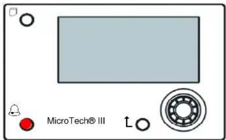
The standard HMI consists of an inbuilt display (A) with 3 buttons (B) and a push'n'roll control (C).
The keypad/display (A) consists of a 5-line by 22 character display. The function of the three buttons (B) is described below:
| Alarm status (from any page it links with the page with alarm list, alarm log and alarm snapshot if available) | |
| Back to Main Page | |
| Back to the previous level (it can be the Main Page) |
The push'n'roll command (C) is used to scroll between the different menu pages, settings and data available on the HMI for the active password level. Rotating the wheel allows to navigate between lines on a screen (page) and to increase and decrease changeable values when editing. Pushing the wheel acts as an Enter Button and will jump from a link to the next set of parameters.
3.1 General Recommendation
Before switching on the unit read the following recommendations:
- When all the operations and all the settings have been carried out, close all the switchbox panels.
- The switchbox panels can only be opened by trained personnel.
- When the UC requires to be accessed frequently the installation of a remote interface is strongly recommended.
- Evaporator, compressors and related inverters are protected from freezing by electrical heaters. These heaters are supplied through unit main supply and temperature controlled by thermostat or by the unit controller. Also the LCD display of the unit controller may be damaged by extremely low temperatures. For this reason, it is strongly recommended to never power off the unit during winter, especially in cold climates.
3.2 Navigating
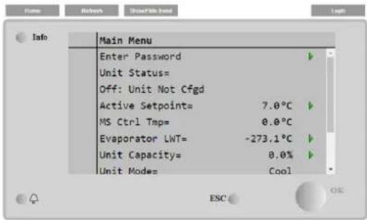
When power is applied to the control circuit, the controller screen will be active and display the Home screen, which can also be accessed by pressing the Menu Button. The navigating wheel is the only navigating device necessary, although the MENU, ALARM, and BACK buttons can provide shortcuts as explained previously.
An example of the HMI screens is shown in the following picture.
A bell ringing in the top right corner will indicate an active alarm. If the bell doesn't move it means that the alarm has been acknowledged but not cleared because the alarm condition hasn't been removed. A LED will also indicate where the alarm is located between the unit or circuits.
The active item is highlighted in contrast, in this example the item highlighted in Main Menu is a link to another page. By pressing the push'n'roll, the HMI will jump to a different page. In this case the HMI will jump to the Enter Password page.
| Enter Password | 2 / 2 | |
| Enter PW | * * * * | |
3.3 Passwords
The HMI structure is based on access levels that means that each password will disclose all the settings and parameters allowed to that password level. Basic informations about the status including the active alarm list, active setpoint and controlled water temperature can be accessed without the need to enter the password. The user UC handles two level of passwords:
| USER | 5321 |
| MAINTENANCE | 2526 |
The following information will cover all data and settings accessible with the maintenance password.
In the Enter Password screen, the line with the password field will be highlighted to indicate that the field on the right can be changed. This represents a setpoint for the controller. Pressing the push'n'roll the individual field will be highlighted to allow an easy introduction of the numeric password. By changing all fields, the 4 digits password will be entered and, if correct, the additional settings available with that password level will be disclosed.
| Enter Password | 2 / 2 |
| Enter PW | 5 * * * |
The password will time out after 10 minutes and is cancelled if a new password is entered or the control powers down. Entering an invalid password has the same effect as continuing without a password.
Once a valid password has been entered, the controller allows further changes and access without requiring the user to enter a password until either the password timer expires or a different password is entered. The default value for this password timer is 10 minutes. It is changeable from 3 to 30 minutes via the Timer Settings menu in the Extended Menus.
3.4 Editing
The Editing Mode is entered by pressing the navigation wheel while the cursor is pointing to a line containing an editable field. Once in the edit mode pressing the wheel again causes the editable field to be highlighted. Turning the wheel clockwise while the editable field is highlighted causes the value to be increased. Turning the wheel counter-clockwise while the editable field is highlighted causes the value to be decreased. The faster the wheel is turned, the faster the value is increased or decreased. Pressing the wheel again cause the new value to be saved and the keypad/display to leave the edit mode and return to the navigation mode.
A parameter with an "R" is read only; it is giving a value or description of a condition. An "R/w" indicates a read and/or write opportunity; a value can be read or changed (providing the proper password has been entered).
3.5 Basic Control System Diagnostic
MicroTech III-IV controller, extension modules and communication modules are equipped with two status LED (BSP and BUS) to indicate the operational status of the devices. The BUS LED indicates the status of the communication with the controller. The meaning of the two status LED is indicated below.
Main Controller (UC)
| BSP LED | Mode |
| Solid Green | Application running |
| Solid Yellow | Application loaded but not running (*) or BSP Upgrade mode active |
| Solid Red | Hardware Error (*) |
| Flashing Green | BSP startup phase. The controller needs time for starting. |
| Flashing Yellow | Application not loaded (*) |
| Flashing Yellow/Red | Fail safe mode (in case that the BSP upgrade was interrupted) |
| Flashing Red | BSP Error (software error*) |
| Flashing Red/Green | Application/BSP update or inizialization |
(*) Contact Service.
Extension modules
| BSP LED | Mode | BUS LED | Mode |
| Solid Green | BSP running | Solid Green | Communication running, I/O working |
| Solid Red | Hardware Error (*) | Solid Red | Communication down (*) |
| Flashing Red | BSP Error (*) | Solid Yellow | Communication running but parameter from the application wrong or missing, or uncorrect factory calibration |
| Flashing Red/Green | BSP upgrade mode |
Communication modules
BSP LED (same for all modules)
| BSP LED | Mode |
| Solid Green | BPS running, communication with controller |
| Solid Yellow | BSP running, no communication with controller (*) |
| Solid Red | Hardware Error (*) |
| Flashing Red | BSP Error (*) |
| Flashing Red/Green | Application/BSP update |
(*) Contact Service.
BUS LED
| BUS LED | LON | Bacnet MSTP | Bacnet IP | Modbus |
| Solid Green | Ready for Communication. (All Parameter loaded, Neuron configured). Doesn't indicate a communication with other devices. | Ready for Communication. The BACnet Server is started. It doesn't indicate an active communication. | Ready for Communication. The BACnet Server is started. It doesn't indicate an active communication. | All Communication running. |
| Solid Yellow | Startup | Startup | Startup. The LED stays yellow until the module receives a IP Address, therefore a link must be established. | Startup, or one configured channel not communicating to the Master. |
| Solid Red | No Communication to Neuron (internal error, could be solved by downloading a new LON application). | BACnet Server down. Automatically a restart after 3 seconds are initiated. | BACnet Server down. Automatic restart after 3 seconds is initiated. | All configured Communications down. Means no communication to the Master. The timeout can be configured. In case that the timeout is zero the timeout is disabled. |
| Flashing Yellow | Communication not possible to the Neuron. The Neuron must be configured and set online over the LON Tool. |
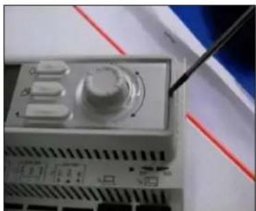
3.6 Controller maintenance
The controller requires to maintain the installed battery. Every two years it's required to replace the battery. Battery model is: BR2032 and it is produced by many different vendors.
To replace the battery remove the plastic cover of the controller display using a screw driver as shown in the following pictures:
natural_image
Close-up of a mechanical device with a pen inserted, no visible text or symbols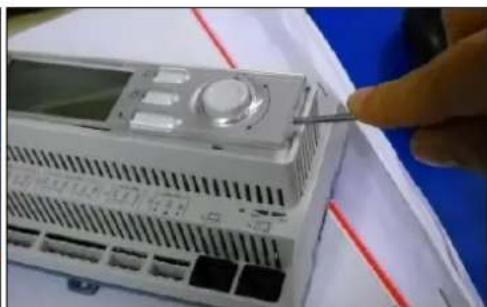
natural_image
Close-up of a white electronic device with a control panel and a finger inserted, placed on a blue surface (no visible text or symbols)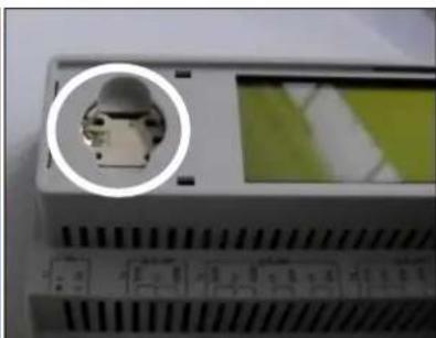
natural_image
Close-up of a device with a circular inset showing a small mechanical component, no visible text or symbols.Be careful to avoid damages to the plastic cover. The new battery shall be placed in the proper battery holder which is highlighted in the picture, respecting the polarities indicated into the holder itself.
3.7 Optional Remote User Interface
As an option an external Remote HMI can be connected on the UC. The Remote HMI offers the same features as the inbuilt display plus the alarm indication done with a light emitting diode located below the bell button.
The Remote can be ordered with the unit and shipped loose as a field installed option. It can also be ordered any time after chiller shipment and mounted and wired on the job as explained on the following page. The remote panel is powered from the unit and no additional power supply is required.
All viewing and setpoint adjustments available on the unit controller are available on the remote panel. Navigation is identical to the unit controller as described in this manual.
The initial screen when the remote is turned on shows the units connected to it. Highlight the desired unit and press the wheel to access it. The remote will automatically show the units attached to it, no initial entry is required.
The Remote HMI can be extended up to 700 m using the process bus connection available on the UC. With a daisy-chain connection as below, a single HMI can be connected to up to 8 units. Refer to the specific HMI manual for details.
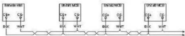
flowchart
graph LR
    A["IR500 I/M"] -->|CE+ CE-| B["CLK"]
    A -->|WNT| C["AND"]
    D["IC5N1 MDS"] -->|CE+ CE-| E["CLK"]
    D -->|WNT| F["AND"]
    G["UN192 MDS"] -->|CE+ CE-| H["CLK"]
    G -->|WNT| I["AND"]
    J["UN140 MDS"] -->|CE+ CE-| K["CLK"]
    J -->|WNT| L["AND"]
3.8 Embedded Web Interface
The MicroTech III-IV controller has an embedded web interface that can be used to monitor the unit when connected to a local network. It is possible to configure the IP addressing of the MicroTech III-IV as a fixed IP of DHCP depending on the network configuration.
With a common web browser a PC can connect with the unit controller entering the IP address of the controller or the host name, both visible in the "About Chiller" page accessible without entering a password.
When connected, it will be required to enter a user name and a password. Enter the following credential to get access to the web interface:
User Name: Daikin
Password: Daikin@web
The Main Menu page will be displayed. The page is a copy of the onboard HMI and follows the same rules in terms of access levels and structure.
In addition, it allows to trend log a maximum of 5 different quantities. It's required to click on the value of the quantity to monitor and the following additional screen will become visible:
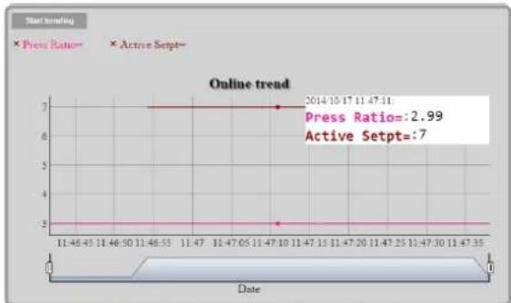
line
| Date | Press Ratio | Active Setpt | | ---------- | ----------- | ------------ | | 2014-10-17 | 2.99 | 7 |Depending on the web browser and its version the trend log feature may not be visible. It's required a web browser supporting HTML 5 like for example:
• Microsoft Internet Explorer v.11,
- Google Chrome v.37,
- Mozilla Firefox v.32.
These softwares are only an example of the browser supported and the versions indicated have to be intended as minimum versions.
4 WORKING WITH THIS UNIT
This section contains a guide on how to deal with the everyday usage of the unit. Next sections describe how to perform routine tasks on the unit, such as:
- Unit Setup
- Unit/Circuit start-up
- Alarm handling
- BMS Control
- Battery replacement
4.1 Unit Setup
Before starting up the unit, some basic settings need to be set by the customer according to the application.
- Control Source
• Available Modes
• Temperature Settings - Alarm Settings
- Pump Settings
• Power Conservation - Date/Time
- Scheduler
4.1.1 Control Source
This function allows to select which source should be used for unit control. The following sources are available:
Local Unit is enabled by local switches placed into the switchbox, chiller mode (cool, cool w/glycol, ice), LWT setpoint and capacity limit are determined by local settings in the HMI. Network Unit is enable by a remote switch, chiller mode, LWT setpoint and capacity limit are determined by an external BMS. This function requires: Remote enable connection to a BMS (unit on/off switch must be in remote) Communication module and its connection to a BMS.
4.1.2 Operating Mode
The following operating modes can be selected through the Available modes setpoint.
| Mode | Description |
| Cool | Set if only chilled water temperature up to 4 °C is required. No glycol is generally needed in the water circuit, unless ambient temperature may reach low values. |
| Cool w/Glycol | Set if only chilled water temperature below 4 °C is required. This operation requires proper glycol/water mixture in the evaporator water circuit. |
| Cool/Ice w/Glycol | Set in case only a dual cool/ice mode is required. This setting implies an operation with double setpoint which is activated through a customer supplied switch, according to the following logic: Switch OFF: The chiller will work in cooling mode with the Cool LWT 1 being as the Active Setpoint.Switch ON: The chiller will work in ice mode with the Ice LWT as the Active Setpoint. |
| Ice w/Glycol | Set if only ice storage is required. The application requires the compressors to operate at full load until the ice bank is completed, and then to stop for at least 12 hours. In this mode the compressor(s) will not operate at part load, but will work only in on/off mode. |
| MultiPurpose | Set in case a contemporary cool/heat mode is required. This setting implies an operation with double functioning,with the Cool LWT 1 as the cooling Active Setpoint andwith the Heat LWT 1 as the heating Active Setpoint. |
| MultiPurpose w/Glycol | Set in case a contemporary cool/heat mode is required. This setting implies an operation with double functioning,with the Cool LWT 1 as the cooling Active Setpoint andwith the Heat LWT 1 as the heating Active Setpoint. |
| MultiPurpose/Ice w/Glycol | Set in case a contemporary cool/heat mode is required. This setting implies an operation with double functioning,with the Ice LWT as the cooling Active Setpoint andwith the Heat LWT 1 as the heating Active Setpoint. |
| Test | Enables the Manual Control of the unit. The manual test feature helps in debugging and checking the operational status of sensors and actuators. This feature is accessible only with the maintenance password in the main menu. To activate the test feature is required to disable the Unit from the Q0 switch and change the available mode to Test (see section 4.2.1). |
4.1.3 Temperature Settings
Setpoint range is limited according to the selected operating mode. The controller includes:
- two set points in cooling mode (either standard cool or cool w/glycol)
- two set points in heating mode
• one set point in ice mode
The above setpoints are activated according to Operating mode, Double Setpoint or Scheduler selection. If the Time Scheduler is enabled the Double Setpoint input state will be ignored by the controller.
The table below lists the LWT Setpoint being activated according to the operation mode, the double setpoint switch status and the scheduler state. The table also reports the defaults and the range allowed for each setpoint.
| Operating Mode | Double Setpoint Input | Scheduler | LWT Setpoint | Default | Range |
| Cool | OFF | off, on Setpoint 1 | Cool LWT 1 | 7.0°C | 4.0°C ÷ 15.0°C |
| ON | On Setpoint 2 | Cool LWT 2 | 7.0°C | 4.0°C ÷ 15.0°C | |
| Ice | N/A | N/A | Ice LWT | -4.0°C | -8.0°C ÷ 4.0°C |
| Heat | OFF | off, on Setpoint 1 | Heat LWT 1 | 45.0°C | 30.0°C ÷ 60.0°C(*) |
| ON | On Setpoint 2 | Heat LWT 2 | 45.0°C | 30.0°C ÷ 60.0°C(*) |
(*) 30.0 °C ÷ 65.0 for HT unit type
The LWT setpoint can be overridden in case the setpoint reset or the quiet mode are activated.
4.1.4 Thermostatic control
Thermostatic control settings, allows to set up the response to temperature variations. Default settings are valid for most application, however plant specific conditions may require adjustments in order to have a smooth control or a quicker response of the unit.
The control will start the first compressor if the controlled temperature is higher (Cool Mode) or lower (Heat Mode) than the active setpoint of at least a Start Up DT value, whereas other compressors are started, step by step, if the controlled temperature is higher (Cool Mode) or lower (Heat Mode) than the active setpoint (AS) of at least a Stage Up DT (SU) value. Compressors stop if performed following same procedure looking to the parameters Stage Down DT and Shut Down DT.
| Cool Mode | Heat Mode | |
| First compressor starts | Controlled Temperature > Setpoint + Start Up DT | Controlled Temperature < Setpoint - Start Up DT |
| Other compressors start | Controlled Temperature > Setpoint + Stage Up DT | Controlled Temperature < Setpoint - Stage Up DT |
| Last compressor stop | Controlled Temperature < Setpoint - Shut Dn DT | Controlled Temperature > Setpoint - Shut Dn DT |
| Other compressors stop | Controlled Temperature < Setpoint - Stage Dn DT | Controlled Temperature > Setpoint - Stage Dn DT |
A qualitative example of compressors start-up sequence in cool mode operation is shown in the graph below.
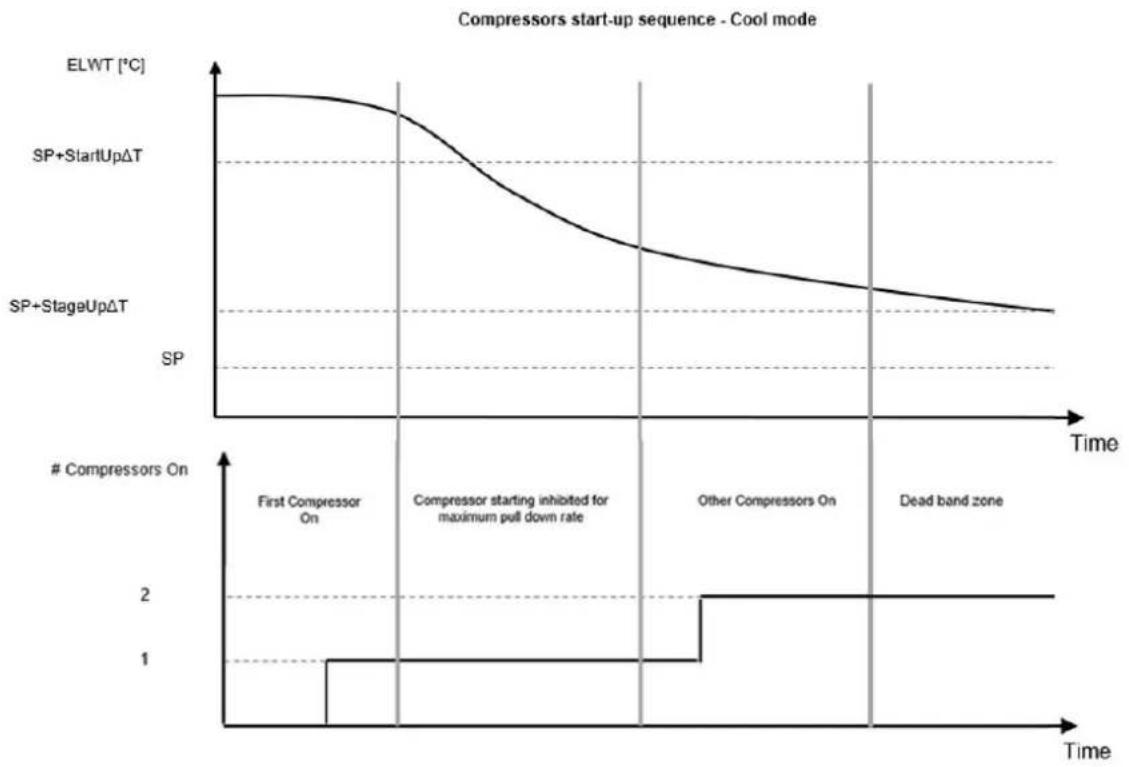
line
| Time Segment | ElWT [°C] | SP+StartUpΔT | SP+StageUpΔT | | ------------------------- | --------- | ------------ | ------------ | | First Compressor On | ~0.8 | - | - | | Compressor starting inhibited for maximum pull down rate | - | - | 1 | | Other Compressors On | - | - | 2 | | Dead band zone | - | - | 2 |When controlled temperature is within the dead band (DB) error from the active setpoint (AS), unit capacity will not be changed.
If the leaving water temperature decreases below (Cool Mode) or rises above (Heat Mode) the active setpoint (AS), unit capacity is adjusted to keep it stable. A further decreasing (Cool Mode) or increasing (Heat Mode) of the controlled temperature of the Shut Down DT offset (SD) can cause circuit shutdown.
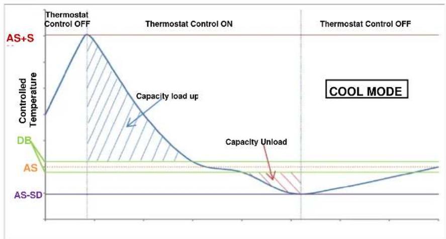
line
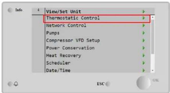
| Phase | Controlled Temperature | | ------------------ | ---------------------- | | AS+S | High | | Capacity load up | Decreasing | | Capacity Unload | Low | | AS-SD | Low |Thermostatic control settings are accessible from Main Page→ view/Set Unit → Thermostatic Control
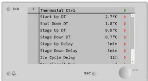
| Parameter | Range | Description |
| C Start Up DT | 1.1-5°C | Delta temperature respect the active setpoint to start the unit in cool mode (startup of first compressor) |
| C Shut Down DT | 1.1-5°C | Delta temperature respect the active setpoint to stop the unit in cool mode (shutdown of latest compressor) |
| H Start Up DT | 1.1-5°C | Delta temperature respect the active setpoint to start the unit in heat mode (startup of first compressor) |
| H Shut Down DT | 1.1-5°C | Delta temperature respect the active setpoint to stop the unit in heat mode (shutdown of latest compressor) |
| Stage Up DT | 0-2.9°C | Delta temperature respect the active setpoint to start a compressor |
| Stage Down DT | 0-1.9°C | Delta temperature respect the active setpoint to stop a compressor |
| Stage Up Delay | 0-60 min | Minimum time between the compressors startup |
| Stage Down Delay | 3-30 min | Minimum time between the compressors shutdown |
| Ice Cycle Delay | 1-23 h | Unit standby period during Ice mode operation |
| Max Circuits Run | 1-2 | Limit to the number of circuits to be used |
| Next Circuit On | Shows next circuit to be started up | |
| Next Circuit Off | Shows next circuit number to be stopped |
4.1.5 Pumps settings
The UC can manage one or two water pumps for both evaporator and, for W/C units, condenser. Number of pumps and their priority can be set from the HMI. The following options are available to control the pump(s):
1 only Set to this in case of single pump or twin pump with only #1 operational (f.e. in case of maintenance on #2).
2 Only Set to this in case of twin pump with only #2 operational (f.e. in case of maintenance on #1).
Auto Set for automatic pump start management. At each chiller start, the pump with the least number of hours will be activated.
1 Primary Set to this in case of twin pump with #1 running and #2 as a backup.
2 Primary Set to this in case of twin pump with #2 running and #1 as a backup.
4.1.6 Alarm Settings
If glycol is present in the water circuits, factory defaults values for the Alarm Limits listed below must be adjusted:
| Parameter | Description |
| Low Press Hold | Set the minimum refrigerant pressure of the unit. It is generally recommended to set to a value whose saturated temperature is 8 to 10 °C below the minimum active setpoint. This will allow a safe operation and a proper control of compressor suction superheat. |
| Low Press Unload | Set lower than the hold threshold enough to allow a suction pressure recovery from fast transients without unloading the compressor. A 20 kPa differential is generally appropriate for most applications. |
| Evap Water Frz | Stops the unit in case the leaving temperature falls below a given threshold. To allow a safe operation of the chiller, this setting must be adequate to the minimum temperature allowed by the mixture water/glycol present in the evaporator water circuit. |
| Cond water Frz | Stops the unit in case the leaving temperature falls below a given threshold. To allow a safe operation of the chiller, this setting must be adequate to the minimum temperature allowed by the mixture water/glycol present in the condenser water circuit. |

When glycol is used in the plant, always disconnect antifreeze electric heater.
4.1.7 Power Conservation
Demand limit function allows the unit to be limited to a specified maximum load. Capacity limit level is defined with an external 4-20 mA signal and linear relationship. 4 mA indicate maximum capacity available whereas 20 mA indicates minimum capacity available.
With demand limit function is not possible shutdown the unit but only unload it until minimum admissible capacity. Demand limit related setpoints available through this menu are listed in the table below.
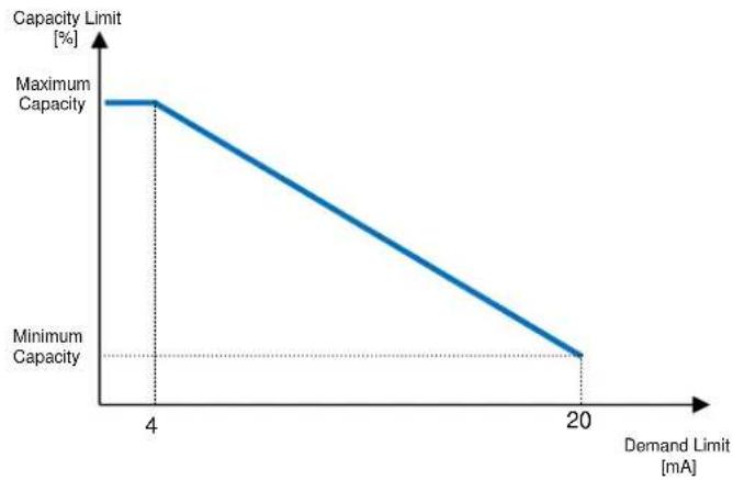
line
| Demand Limit [mA] | Capacity Limit [%] | |---|---| | 4 | Maximum Capacity | | 20 | Minimum Capacity || Parameter | Description |
| Unit Capacity | Displays current unit capacity |
| Demand Limit En | Enables demand limit |
| Demand Limit | Displays active demand limit |
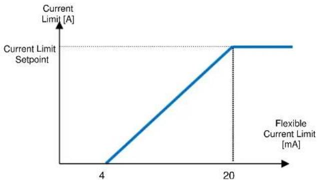
4.1.7.2 Current Limit (Optional)
Current limit function allows to control unit power consumption taking current drawn below a specific limit. Starting from the Current Limit Setpoint defined through the HMI or BAS communication, user can decrease the real limit using an external 4-20mA signal as indicate in the graph below. With 20 mA real current limit is set to Current Limit Setpoint, whereas with 4 mA signal the unit is unloaded until minimum capacity.
line
| Current Limit [A] | Flexible Current Limit [mA] | | ----------------- | ---------------------------- | | 0 | 0 | | 4 | 4 | | 20 | 20 |4.1.7.3 Setpoint Reset
The setpoint reset function overrides the water temperature setpoints selected through the interface, when certain circumstances occur. This feature helps in reducing energy consumption optimizing comfort as well. Three different control strategies can be selected:
- Setpoint Reset by Outside Air Temperature (OAT)
- Setpoint Reset by an external signal (4-20mA)
- Setpoint Reset by Evaporator T (Return)
The following setpoints are available through this menu:
| Parameter | Description |
| Setpoint Reset | Set the Setpoint Reset mode (None, 4-20 mA, Return, OAT) |
| Max Reset | Max Setpoint Reset (valid for all active modes) |
| Start Reset DT | Used on Setpoint Reset by Evaporator DT |
| Max Reset OAT | See Setpoint Reset by OAT Reset |
| Strt Reset OAT | See Setpoint Reset by OAT Reset |
4.1.7.4 Setpoint Reset by OAT Reset
The active setpoint is calculated applying a correction which is a function of ambient temperature (OAT). As temperature drops below the Start Reset OAT (SROAT), Cool LWT setpoint is gradually increased until OAT reaches the Max Reset OAT value (MROAT). Beyond this value, the Cool LWT setpoint is increased by the Max Reset (MR) value. As temperature grow over the Start Reset OAT (SROAT), Heat LWT setpoint is gradually reduced until OAT reaches the Max Reset OAT value (MROAT). Above this value, the Heat LWT setpoint is decreased by the Max Reset (MR) value.
4.1.7.5 Setpoint Reset by External 4-20 mA Signal
The active setpoint is calculated applying a correction based on an external 4-20mA signal. 4 mA corresponds to 0 °C correction, while 20 mA corresponds to a correction of the active setpoints as set in Max Reset (MR).
4.1.7.6 Setpoint Reset by Evaporator Return Temperature
The active cooling setpoint is calculated applying a correction that depends on the evaporator entering (return) water temperature. The active heating setpoint is calculated applying a correction that depends on the condenser entering (return) water temperature.

The Return Reset may affect negatively the chiller operation when operated with variable flow. Avoid to use this strategy in case of inverter water flow control.
4.1.8 Date/Time
4.1.8.1 Date, Time and UTC Settings
Date, time and UTC settings are available in the HMI.
4.1.8.2 Quiet Mode Scheduling
The Quiet Mode can be used to reduce chiller noise in certain hours of the day when noise reduction is more important than cooling operation, like for example in night time. When Quiet Mode is activated, the LWT setpoint is increased by the maximum setpoint reset (MR) described in the chapter "Setpoint Reset", thus forcing a capacity limitation to the unit without losing control on chilled water temperature. Also, condenser temperature target is increased by a value set in "QM Cond Offset". In this way condenser fans are forced to reduce speed without losing control on condensation. Quiet mode is timer enabled.

The Quiet Mode may affect negatively chiller efficiency due to the increased condenser setpoint
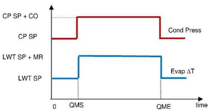
line
| Process | Value | | --------------- | ----- | | CP SP + CO | High | | CP SP | Low | | LWT SP + MR | Low | | LWT SP | Low | | Cond Press | High | | Evap ΔT | Low || Parameter | Default | Range |
| Quiet Mode | Disable | Disable, Enable |
| QM Start Hr (QMS) | 21h | 0...24h |
| QM Start Min | 0min | 0...60min |
| QM End Hr (QME) | 6h | 0...24h |
| QM End Min | 0min | 0...60min |
| QM Cond Offset (CO) | 5°C | 0...10°C |
4.1.9 Scheduler
Unit On/Off can be managed automatically through the function Time Scheduler enabled when the parameter Unit Enable is set to Scheduler. For each day of the week user can define six time slots and choose for each time slot one of following mode:
| Parameter | Description |
| off | Unit Off |
| On Setpoint 1 | Unit On and Cool LWT 1 is the active setpoint |
| On Setpoint 2 | Unit On and Cool LWT 2 is the active setpoint |
4.2 Unit/Circuit Start-up
In this section, starting and stopping sequence of the unit will be described. status will be briefly described to allow a better understanding of what is going on into the chiller control.
4.2.1 Prepare the unit to start
4.2.1.1 Unit Enable
The unit starts only if all the enable setpoints/signals are active:
- Unit Switch Enable (signal) = Enable
- Keypad Enable (setpoint) = Enable
• BMS Enable (setpoint) = Enable
| Switch Enable | Software Enable | BMS Enable | Unit Status | ||
| Q0 | State | Chiller Enable (KeyPad Enable set point) | Control Source (Set point) | BAS request | |
| 0 | X | X | X | X | DISABLED |
| LOCAL | X | Disable | X | X | DISABLED |
| LOCAL | X | X | Network | DISABLE | DISABLED |
| LOCAL | X | Enable | Local | X | ENABLED |
| LOCAL | X | Enable | Network | ENABLE | ENABLED |
| REMOTE | Open | X | X | X | DISABLED |
| REMOTE | X | Disable | X | X | DISABLED |
| REMOTE | Closed | Enable | Network | DISABLE | DISABLED |
| REMOTE | Closed | Enable | Local | X | ENABLED |
| REMOTE | Closed | Enable | Network | ENABLE | ENABLED |
4.2.1.2 Switch Enable
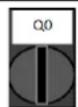
Each unit is equipped with a Main selector installed outside the front panel of the unit switchbox. As shown in the pictures below, for TZ and TZ B units three different positions can be selected: Local, Disable, Remote:
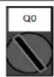
Local With the Q0 switch in this position the unit is enabled. Pump will start if all other enable signals are set to enable and at least one compressor is available to run.
Disable With the Q0 switch in this position the unit is disabled. Pump will not start in normal operational condition. Compressor are kept disabled independently from the status of the individual enable switches.
Remote With the Q0 switch in this position the unit can be enabled using the additional connections available on the connection terminals. A closed loop will identify an enable signal, this can come from a remote switch or a timer by example.
The Keypad enable setpoint is not accessible by user password level. If it is set to "Disable", contact your local maintenance service to check if it can be changed to Enable.
4.2.1.4 BMS Enable
The last enable signal is coming through the high level interface, that is from a Building Management System. The unit can be enabled/disabled from a BMS connected to the UC using a communication protocol. In order to control the unit over the network, the Control Source setpoint must be turned in "Network" (default is Local) and Network En Sp must be "Enable". If disabled, check with your BAS company how the chiller is operated.
4.2.2 Unit Status
One of the texts strings listed in the table below will inform, on the HMI, about the Unit Status.
| Overall Status | Status text | Description |
| off: | Keypad Disable | The Unit has been disabled by keypad. Check with your local maintenance if it can be enabled. |
| Loc/Rem Switch | The Local/Remote enable switch is set to disable. Turn it to Local to enable the unit to start its starting sequence. | |
| BAS Disable | Unit is disabled by BAS/BMS system. Check with the BAS company how to start the unit. | |
| Master Disable | Unit is disabled by the Master Slave function. | |
| Scheduler Disabled | Unit is disabled by the time scheduler. | |
| Unit Alarm | A unit alarm is active. Check the alarm list to see what is the active alarm inhibiting the unit to start and check if the alarm can be cleared. Refer to section 5. before proceeding. | |
| Test Mode | Unit mode set to Test. This mode is activated to check operability of onboard actuators and sensors. Check with the local maintenance if the Mode can be reverted to the one compatible with unit application (View/Set Unit - Set-Up - Available Modes). | |
| All Cir Disabled | No circuit is available to run. All circuits can be disabled by their individual enable switch or can be disabled by a component safety condition active or can be disabled by keypad or can be all in alarms. Check the individual circuit status for further details. | |
| Ice Mode Tmr | This status can be shown only if the unit can work in Ice Mode. The unit is off because the Ice setpoint has been satisfied. Unit will remain off until the Ice Timer has expired. | |
| OAT Lockout | The unit cannot run because the Oustide Air Temperature is below the lim foreseen for the condenser temperature control system installed in this Unit. If the Unit has to run anyway check with your local maintenance how to proceed. | |
| Auto | Unit is in Auto control. The pump is running and at least one compressor i running. | |
| Auto: | Evap Recirc | Unit is running the evaporator pump to equalize the water temperature in the evaporator. |
| Wait For Flow | Unit pump is running but the flow signal still indicate a lack of flow through the evaporator. | |
| Wait For Load | Unit is in standby because the thermostat control satisfied the active setpoint. | |
| Unit Cap Limit | Demand limit has been hit. Unit capacity will not further increase. | |
| Current Limit | Maximum current has been hit. Unit capacity will not further increase. | |
| Noise Reduction | Unit is running with the Quiet Mode activated. Active setpoint may differ from what has been set as cooling setpoint. | |
| Max Pulldn | Unit thermostat control is limiting the unit capacity because the water temperature is dropping at a rate that could exceed the active setpoint. | |
| Pumpdn | Unit is shutting down. |
4.2.3 Circuits Enable
As for the unit enable, the circuits can start only if all the enable setpoints/signals are active:
- Circuit Switch Enable (signal) = Enable
- Keypad Enable (setpoint) = Enable
| Switch Enable | Software Enable | Circuit Status | |
| Q1/Q2 | State | Circuit Enable(KeyPad Enable set point) | |
| 0 | Disabled | X | DISABLED |
| 0 | Disabled | X | DISABLED |
| 1 | Enabled | Disable | DISABLED |
| 1 | Enabled | Enable | ENABLED |
4.2.4 Circuit Status
One of the texts strings listed in the table below will inform, on the HMI, about the Circuit Status.
| Overall Status | Status | Description |
| off: | Ready | Circuit is off waiting for a stage up signal from thermostat control. |
| Stage Up Delay | Circuit is off waiting for the stage up delay to expire. | |
| Cycle Timer | Circuit is off waiting for the compressor cycle timer to expire. | |
| BAS Disable | Circuit is off by BAS signal. Check with the BAS company how to start the unit. | |
| Keypad Disable | Circuit is off by the local or remote HMI. Check with your local maintenance if it can be enabled. | |
| Circuit Switch | Circuit is off by Enable switch. Turn the Enable switch to 1 to allow the circuit start up procedure to start. | |
| Oil Heating | Circuit is off because the oil temperature is too low to guarantee a proper lubrication of compressor. Heating resistor is activated to eliminate this temporary condition. It's suggested to power up the unit in advance to avoid this limiting condition. | |
| Alarm | A circuit alarm is active. Check the alarm list to see what is the active alarm inhibiting the circuit to start and check if the alarm can be cleared. Refer to section 5.before proceeding. | |
| Test Mode | Circuit mode set to Test. This mode is activated to check operability of onboard circuit actuators and sensors. Check with the local maintenance if the Mode can be reverted to Enable. | |
| Max Comp Starts | Compressor starts exceed the maximum number of starts per hour. | |
| VFD Heating | Inverter on compressor cannot start because of low internal temperature. Heating resistor is activated to eliminate this temporary condition. It's suggested to power up the unit in advance to avoid this limiting condition. | |
| Maintenance | A component needs to be replaced or maintained. Refer to section 5.before proceeding. | |
| EXV | Preopen | EXV prepositioning before compressor starts. |
| Run: | Pumpdown | Circuit is shutting down because of thermostat control or pumpdown alarm or because the enable switch has been turned to off. |
| Normal | Circuit is running within the expected operational conditions. | |
| Disch SH Low | Discharge superheat is below the acceptable value. This is a temporary condition that should disappear after few minutes of operation. | |
| Evap Press Low | Circuit is running with low evaporator pressure. This could be due to a transitory condition or a lack of refrigerant. Check with the local maintenance if corrective actions are required. Circuit is protected by preventive logic. | |
| Cond Press High | Circuit is running with high condenser pressure. This could be due to a transitory condition or high ambient temperature or problems with the condenser fans. Check with the local maintenance if corrective actions are required. Circuit will be protected by preventive logic. | |
| High LWT Limit | Circuit is running with a high water temperature. This is a temporary condition that will limit the maximum compressor capacity. Reduction of the water temperature will allow the compressor to reach the full capacity. | |
| High VFD Amps | Inverter current is higher than the maximum allowed current. Preventive logic will protect the inverter. |
4.2.5 Circuit Preventions
4.2.5.1 High Water Temperature Limit
The only prevention that can activate at unit level will limit the maximum unit capacity to 80% when the leaving water temperature exceeds 25 °C in cooling or 60 °C in heating. This condition will be displayed at circuit level to indicate the capacity limitation.
| Symptom | Cause | Solution |
| Unit maximum capacity equal to 80% | Leaving Evaporator water temperature higher than 25 °C or Leaving Condenser water temperature higher than 60 °C | Wait until the water temperature drops below 25 °C |
4.2.5.2 Low Evaporating Pressure
When the circuit is running and the evaporating pressure drops below the safety limits the circuit control logic reacts at two different levels in order to recover the normal running conditions.
If the evaporating pressure drops below the Low Pressure Hold limit, compressor is inhibited to increase its running capacity. This condition is indicated on the controller display in the circuit status as "Run: Evap Press Low". The status is automatically cleared when the evaporating pressure rise above the Low Pressure Hold limit by 14 kPa.
If the evaporating pressure drops below the Low Pressure Unid limit, compressor is unloaded in order to recover the normal operating conditions. This condition is indicated on the controller display in the circuit status as "Run: Evap Press Low". The status is automatically cleared when the evaporating pressure rise above the Low Pressure Hold limit by 14 kPa.
See section 5.6.18 to troubleshoot this problem.
4.2.5.3 High Condensing Pressure
When the circuit is running and the condensing pressure rises above the safety limits the circuit control logic reacts at two different levels in order to recover the normal running conditions.
The two different levels, called High Pressure Hold and High Pressure Unload limits, are calculated by the controller from the maximum condenser pressure allowed by the compressor envelope. This value depends from evaporating pressure as reported in the figure below.
If the condensing pressure rises above the High Pressure Hold limit, compressor is inhibited to increase its running capacity. This condition is indicated on the controller display in the circuit status as "Run: Cond Press High". The limit is calculated in terms of saturated condensing temperature; the status is automatically cleared when the saturated condensing temperature rises above the High Pressure Hold limit by 5.6 °C.
If the condensing pressure rises above the High Pressure Unload limit, compressor is unloaded in order to recover the normal operating conditions. This condition is indicated on the controller display in the circuit status as "Run: Cond Press High". The status is automatically cleared when the saturated condensing temperature rises above the High Pressure Hold limit by 5.6 °C. See section 5.6.17 to troubleshoot this problem.
line
| State | Temperature Range | | ----------------- | ------------------ | | Hi Press Trip | 0 to 1 | | Hi Press Hold | 0 to 1 | | Hi Press Unload | 0 to 1 |4.2.5.4 High Vfd Current
When the compressor is running and its output current rises above the safety limits the circuit control logic reacts at two different levels in order to recover the normal running conditions. Safety limits are calculated by the controller based on the selected compressor type.
If the running current rises above the Running Current Hold limit (101% of RLA), compressor is inhibited to increase its running capacity. This condition is indicated on the controller display in the circuit status as "Run: High VFD Amps".
If the condensing pressure rises above the Running Current Unload limit (105% of RLA), compressor is unloaded in order to recover the normal operating conditions. This condition is indicated on the controller display in the circuit status as "Run: High VFD Amps". The status is automatically cleared when the running amps falls below the hold limit.
4.2.5.5 High Discharge Temperature
When the compressor is running and its discharge temperature rises above the safety limits the circuit control logic reacts at two different levels in order to recover the normal running conditions.
If the discharge temperature rises above the Discharge Temperature Hold limit (95 °C), compressor is inhibited to increase its running capacity. This condition is indicated on the controller display in the circuit status as "Run: High Discharge Temp".
If the discharge temperature rises above the Discharge Temperature Unload limit (100 °C), compressor is unloaded in order to recover the normal operating conditions. This condition is indicated on the controller display in the circuit status as "Run: High Discharge Temp". The status is automatically cleared when the discharge temperature falls below the hold limit.
5 TROUBLESHOOTING
The UC protects the unit and the components from operating in abnormal conditions. Protections can be divided in preventions and alarms. Alarms can then be divided in pump-down and rapid stop alarms. Pump-down alarms are activated when the system or sub-system can perform a normal shutdown in spite of the abnormal running conditions. Rapid stop alarms are activated when the abnormal running conditions require an immediate stop of the whole system or sub-system to prevent potential damages.
The UC displays the active alarms in a dedicated page and keep an history of the last 50 entries divided between alarms and acknowledges occurred. Time and date for each alarm event and of each alarm acknowledge are stored.
The UC also stores alarm snapshot of each alarm occurred. Each item contains a snapshot of the running conditions right before the alarm has occurred. Different sets of snapshots are programmed corresponding to unit alarms and circuit alarms holding different information to help the failure diagnosis.
In the following sections it will also be indicated how each alarm can be cleared between local HMI, Network (by any of the high level interfaces Modbus, Bacnet or Lon) or if the specific alarm will clear automatically. The following symbols are used:
Allowed
☒ Not allowed
□ Not foreseen
5.1 Unit Alerts
5.1.1 Bad Current Limit Input
This alarm is generated when the Flexible Current Limit option has been enabled and the input to the controller is out of the admitted range.
| Symptom | Cause | Solution |
| Unit status is Run.Bell icon is moving on controller's display.Flexible Current Limit function cannot be used.String in the alarm list:BadCurrentLimitInputString in the alarm log:± BadCurrentLimitInputString in the alarm snapshotBadCurrentLimitInput | Flexible current limit input out of range.For this warning out of range is considered to be a signal less than 3mA or more than 21mA. | Check for values of input signal to the unit controller. It has to be in the allowed mA range. |
| Check for electrical shielding of wirings. | ||
| Check for right value of the unit's controller output in case input signal is into allowed range. | ||
| Reset | Notes | |
| Local HMINetworkAuto | ☐☐☑ | Automatically clears when the signal returns in the allowed range. |
5.1.2 Bad Demand Limit Input
This alarm is generated when the Demand Limit option has been enabled and the input to the controller is out of the admitted range.
| Symptom | Cause | Solution |
| Unit status is Run.Bell icon is moving on controller's display.Demand Limit function cannot be used.String in the alarm list:BadDemandLimitInputString in the alarm log:±BadDemandLimitInputString in the alarm snapshotBadDemandLimitInput | Demand limit input out of range.For this warning out of range is considered to be a signal less than 3mA or more than 21mA. | Check for values of input signal to the unit controller. It has to be in the allowed mA range. |
| Check for electrical shielding of wirings. | ||
| Check for right value of the unit's controller output in case input signal is into allowed range. | ||
| Reset | Notes | |
| Local HMINetworkAuto | ☐☐☑ | Automatically clears when the signal returns in the allowed range. |
5.1.3 Bad Leaving Water Temperature Reset Input
This alarm is generated when the Setpoint Reset option has been enabled and the input to the controller is out of the admitted range.
| Symptom | Cause | Solution |
| Unit status is Run.Bell icon is moving on controller's display.LWT Reset function cannot be used.String in the alarm list:BadSetPtOverrideInputString in the alarm log:± BadSetPtOverrideInputString in the alarm snapshotBadSetPtOverrideInput | LWT reset input signal is out of range.For this warning out of range is considered to be a signal less than 3mA or more than 21mA. | Check for values of input signal to the unit controller. It has to be in the allowed mA range. |
| Check for electrical shielding of wirings. | ||
| Check for right value of the unit's controller output in case input signal is into allowed range. | ||
| Reset | Notes | |
| Local HMINetworkAuto | □□☑ | Automatically clears when the signal returns in the allowed range. |
5.1.4 Condenser Pump #1 Failure
This alarm is generated if the pump is started but the flow switch is not able to close within the recirculate time. This can be a temporary condition or may be due to a broken flowswitch, the activation of circuit breakers, fuses or to a pump breakdown.
| Symptom | Cause | Solution |
| Unit could be ON.Bell icon is moving on controller's display.Backup pump is used or stop of all circuits in case of pump #2 failure.String in the alarm list:CondPump1FaultString in the alarm log:± CondPump1FaultString in the alarm snapshotCondPump1Fault | Pump #1 may not be operating. | Check for problem in electrical wiring of the pump #1. |
| Check that electrical breaker of pump #1 is tripped. | ||
| If fuses are used to protect the pump, check the integrity of fuses. | ||
| Check for problem in wiring connection between pump starter and unit controller. | ||
| Check the water pump filter and the water circuit for obstructions. | ||
| Flow Switch doesn't operate properly | Check flow switch connection and calibration. | |
| Reset | Notes | |
| Local HMINetworkAuto | ☑☑☐ |
5.1.5 Condenser Pump #2 Failure
This alarm is generated if the pump is started but the flow switch is not able to close within the recirculate time. This can be a temporary condition or may be due to a broken flowswitch, the activation of circuit breakers, fuses or to a pump breakdown.
| Symptom | Cause | Solution |
| Unit could be ON.Bell icon is moving on controller's display.Backup pump is used or stop of all circuits in case of pump #1 failure.String in the alarm list:CondPump2FaultString in the alarm log:± CondPump2FaultString in the alarm snapshotCondPump2Fault | Pump #1 may not be operating. | Check for problem in electrical wiring of the pump #1. |
| Check that electrical breaker of pump #1 is tripped. | ||
| If fuses are used to protect the pump, check the integrity of fuses. | ||
| Check for problem in wiring connection between pump starter and unit controller. | ||
| Check the water pump filter and the water circuit for obstructions. | ||
| Flow Switch doesn't operate properly | Check flow switch connection and calibration. | |
| Reset | Notes | |
| Local HMINetworkAuto | ☑☑☐ |
5.1.6 Energy Meter Communication Fail
This alarm is generated in case of communication problems with the energy meter.
| Symptom | Cause | Solution |
| Bell icon is moving on controller's display.String in the alarm list:EnergyMtrCommFailString in the alarm log:± EnergyMtrCommFailString in the alarm snapshotEnergyMtrCommFail | Module has no power supply | Refer to the datasheet of the specific component to see if it is correctly powered. |
| Wrong cabling with the Unit Controller | Check if the polarity of the connections is respected. | |
| Modbus parameters not properly set | Referring to the datasheet of the specific component to see if the modbus parameters are set correctly:Address = 20Baud Rate =19200 kBsParity = NoneStop bits =1 | |
| Module is broken | Check if the display shows something and the power supply is present. | |
| Reset | Notes | |
| Local HMINetworkAuto | ☐☐☑ | Automatically clears when the communication is re-established. |
5.1.7 Evaporator Pump #1 Failure
This alarm is generated if the pump is started but the flow switch is not able to close within the recirculate time. This can be a temporary condition or may be due to a broken flowswitch, the activation of circuit breakers, fuses or to a pump breakdown.
| Symptom | Cause | Solution |
| Unit could be ON.Bell icon is moving on controller's display.Backup pump is used or stop of all circuits in case of pump #2 failure.String in the alarm list:EvapPump1FaultString in the alarm log:± EvapPump1FaultString in the alarm snapshotEvapPump1Fault | Pump #1 may not be operating. | Check for problem in electrical wiring of the pump #1. |
| Check that electrical breaker of pump #1 is tripped. | ||
| If fuses are used to protect the pump, check the integrity of fuses. | ||
| Check for problem in wiring connection between pump starter and unit controller. | ||
| Check the water pump filter and the water circuit for obstructions. | ||
| Flow Switch doesn't operate properly | Check flow switch connection and calibration. | |
| Reset | Notes | |
| Local HMINetworkAuto | ☑☑☐ |
5.1.8 Evaporator Pump #2 Failure
This alarm is generated if the pump is started but the flow switch is not able to close within the recirculate time. This can be a temporary condition or may be due to a broken flowswitch, the activation of circuit breakers, fuses or to a pump breakdown.
| Symptom | Cause | Solution |
| Unit could be ON.Bell icon is moving on controller's display.Backup pump is used or stop of all circuits in case of pump #1 failure.String in the alarm list:EvapPump2FaultString in the alarm log:± EvapPump2FaultString in the alarm snapshotEvapPump2Fault | Pump #2 may not be operating. | Check for problem in electrical wiring of the pump #2. |
| Check that electrical breaker of pump #2 is tripped. | ||
| If fuses are used to protect the pump, check the integrity of fuses. | ||
| Check for problem in wiring connection between pump starter and unit controller. | ||
| Check the water pump filter and the water circuit for obstructions. | ||
| Flow Switch doesn't operate properly | Check flow switch connection and calibration. | |
| Reset | Notes | |
| Local HMINetworkAuto | ☑☑☐ |
5.1.9 External Event
This alarm indicates that a device, whose operation is linked with this unit, is reporting a problem on the dedicated input.
| Symptom | Cause | Solution |
| Unit status is Run.Bell icon is moving on controller's display.String in the alarm list:UnitExternalEventString in the alarm log:± UnitExternalEventString in the alarm snapshotUnitExternalEvent | There is an external event that has caused the opening, for at least 5 seconds of the digital input on the controller board. | Check for reasons of external event and if it can be a potential problem for a correct chiller operation. |
| Reset | Notes | |
| Local HMINetworkAuto | ☐☐☑ | The alarm is automatically cleared when the problem is solved. |
| NOTE: What above applies in case of configuration of the external fault digital input as Event. | ||
5.1.10 Fan Alarm Module Communication Fail
This alarm is generated in case of communication problems with the FAC module.
| Symptom | Cause | Solution |
| Bell icon is moving on controller's display. String in the alarm list: FanMdlCommFail String in the alarm log: ± FanMdlCommFail String in the alarm snapshot FanMdlCommFail | Module has no power supply | Check the power supply from the connector on the side of the module. |
| Check if LEDs are both green. | ||
| Check if the connector on the side is tightly inserted in the module | ||
| Module address is not properly set | Check if module's address is correct referring to the wiring diagram. | |
| Module is broken | Check if LED are on and both green. If BSP LED is solid red replace the module | |
| Check if power supply is ok but LEDs are both off. In this case replace the module | ||
| Reset | Notes | |
| Local HMI Network Auto | ☑ ☑ |
5.1.11 Heat Recovery Entering Water Temperature sensor fault
This alarm is generated any time that the input resistance is out of an acceptable range.
| Symptom | Cause | Solution |
| Unit status is Off.All circuits are stopped with a normal shutdown procedure.Bell icon is moving on controller's display.String in the alarm list:UnitAlHREwtSenString in the alarm log:± UnitAlHREwtSenString in the alarm snapshotUnitAlHREwtSen | Sensor is broken. | Check for sensor integrity according table and allowed kOhm (kΩ) range. |
| Check correct sensors operation | ||
| Sensor is shorted. | Check if sensor is shorted with a resistance measurement. | |
| Sensor is not properly connected (open). | Check for absence of water or humidity on electrical contacts. | |
| Check for correct plug-in of the electrical connectors. | ||
| Check for correct sensors wiring also according electrical scheme. | ||
| Reset | Notes | |
| Local HMINetworkAuto | ☑☑☐ |
5.1.12 Heat Recovery Leaving Water Temperature sensor fault
This alarm is generated any time that the input resistance is out of an acceptable range.
| Symptom | Cause | Solution |
| Heat Recovery is OffBell icon is moving on controller's display.String in the alarm list:UnitAlHRLvgSenString in the alarm log:± UnitAlHRLvgSenString in the alarm snapshotUnitAlHRLvgSen | Sensor is broken. | Check for sensor integrity according table and allowed kOhm (kΩ) range. |
| Check correct sensors operation | ||
| Sensor is shorted. | Check if sensor is shorted with a resistance measurement. | |
| Sensor is not properly connected (open). | Check for absence of water or humidity on electrical contacts. | |
| Check for correct plug-in of the electrical connectors. | ||
| Check for correct sensors wiring also according electrical scheme. | ||
| Reset | Notes | |
| Local HMINetworkAuto | ☑☑☐ |
5.1.13 Heat Recovery Water Temperatures inverted
This alarm is generated any time that the heat recovery entering water temperature is lower than the leaving by 1 °C and at least one compressor is running.
| Symptom | Cause | Solution |
| Bell icon is moving on controller's display.Bell icon is moving on controller's display.String in the alarm list:Unit HRInvAlString in the alarm log:± Unit HRInvAlString in the alarm snapshotUnit HRInvAl | Entering and leaving water temperature sensors are inverted. | Check cabling of the sensors on the unit controller. |
| Check offset of the two sensors with the water pump running | ||
| Entering and leaving water pipes are reversed. | Check if the water flows in counter flow respect to refrigerant. | |
| Water pump operate reverse. | Check if the water flows in counter flow respect to refrigerant. | |
| Reset | Notes | |
| Local HMINetworkAuto | ☑☑☐ |
5.1.14 Rapid Recovery Module Communication Fail
This alarm is generated in case of communication problems with the RRC module.
| Symptom | Cause | Solution |
| Bell icon is moving on controller's display. String in the alarm list: RpdRcvryCommFail String in the alarm log: ± RpdRcvryCommFail String in the alarm snapshot RpdRcvryCommFail | Module has no power supply | Check the power supply from the connector on the side of the module. |
| Check if LEDs are both green. | ||
| Check if the connector on the side is tightly inserted in the module | ||
| Module address is not properly set | Check if module's address is correct referring to the wiring diagram. | |
| Module is broken | Check if LED are on and both green. If BSP LED is solid red replace the module | |
| Check if power supply is ok but LEDs are both off. In this case replace the module | ||
| Reset | Notes | |
| Local HMI Network Auto | ☑ ☑ |
5.1.15 Switch Box Temperature sensor fault
This alarm is generated any time that the input resistance is out of an acceptable range.
| Symptom | Cause | Solution |
| Unit status is OnBell icon is moving on controller's display.Bell icon is moving on controller's display.String in the alarm list:SwitchBoxTempSenString in the alarm log:± SwitchBoxTempSenString in the alarm snapshotSwitchBoxTempSen | Sensor is broken. | Check for sensor integrity according table and allowed kOhm (kΩ) range. |
| Check correct sensors operation | ||
| Sensor is shorted. | Check if sensor is shorted with a resistance measurement. | |
| Sensor is not properly connected (open). | Check for absence of water or humidity on electrical contacts. | |
| Check for correct plug-in of the electrical connectors. | ||
| Check for correct sensors wiring also according electrical scheme. | ||
| Reset | Notes | |
| Local HMINetworkAuto | ☑☑☐ |
5.1.16 Condenser over heat fault
This alarm is generated if CEWT or CLWT are over the unit envelope operating (65 °C).
| Symptom | Cause | Solution |
| Unit status is OnBell icon is moving on controller's display.Bell icon is moving on controller's display.String in the alarm list:CondWaterOverHeatString in the alarm log:± CondWaterOverHeatString in the alarm snapshotCondWaterOverHeat | Entering water temperature over unit envelope limit. | Check if Unit is working inside allowed envelope. |
| Reset | Notes | |
| Local HMINetworkAuto | ☑☑☑ |
5.2 Unit Pumpdown Stop Alarms
5.2.1 Condenser Entering Water Temperature (EWT) sensor fault
This alarm is generated any time the input resistance is out of an acceptable range.
| Symptom | Cause | Solution |
| Unit status is Off.All circuits are stopped with a normal shutdown procedure.Bell icon is moving on controller's display.String in the alarm list:UnitOffCndEntwTempSenString in the alarm log:± UnitOffCndEntwTempSenString in the alarm snapshotUnitOffcndEntwTempSen | Sensor is broken. | Check for sensor integrity according table and allowed kOhm (kΩ) range. |
| Check correct sensors operation | ||
| Sensor is shorted. | Check if sensor is shorted with a resistance measurement. | |
| Sensor is not properly connected (open). | Check for absence of water or humidity on electrical contacts. | |
| Check for correct plug-in of the electrical connectors. | ||
| Check for correct sensors wiring also according electrical scheme. | ||
| Reset | Notes | |
| Local HMINetworkAuto | ☑☑☐ |
5.2.2 Condenser Leaving Water Temperature (LWT) sensor fault
This alarm is generated any time the input resistance is out of an acceptable range.
| Symptom | Cause | Solution |
| Unit status is Off.All circuits are stopped with a normal shutdown procedure.Bell icon is moving on controller's display.String in the alarm list:UnitOffCndLvgwTempSenString in the alarm log:± UnitOffCndLvgwTempSenString in the alarm snapshotUnitOffcndLvgwTempSen | Sensor is broken. | Check for sensor integrity according table and allowed kOhm (kΩ) range. |
| Check correct sensors operation | ||
| Sensor is shorted. | Check if sensor is shorted with a resistance measurement. | |
| Sensor is not properly connected (open). | Check for absence of water or humidity on electrical contacts. | |
| Check for correct plug-in of the electrical connectors. | ||
| Check for correct sensors wiring also according electrical scheme. | ||
| Reset | Notes | |
| Local HMINetworkAuto | ☑☑☐ |
5.2.3 Evaporator Entering Water Temperature (EWT) sensor fault
This alarm is generated any time the input resistance is out of an acceptable range.
| Symptom | Cause | Solution |
| Unit status is Off.All circuits are stopped with a normal shutdown procedure.Bell icon is moving on controller's display.String in the alarm list:UnitOffEvpEntwTempSenString in the alarm log:± UnitOffEvpEntwTempSenString in the alarm snapshotUnitOffEvpEntwTempSen | Sensor is broken. | Check for sensor integrity according table and allowed kOhm (kΩ) range. |
| Check correct sensors operation | ||
| Sensor is shorted. | Check if sensor is shorted with a resistance measurement. | |
| Sensor is not properly connected (open). | Check for absence of water or humidity on electrical contacts. | |
| Check for correct plug-in of the electrical connectors. | ||
| Check for correct sensors wiring also according electrical scheme. | ||
| Reset | Notes | |
| Local HMINetwork | ☑☑ |
5.2.4 Evaporator Water Temperatures inverted
This alarm is generated any time the entering water temperature is lower than the leaving by 1 °C and at least one compressor is running since 90 seconds.
| Symptom | Cause | Solution |
| Unit status is Off.All circuits are stopped with a normal shutdown procedure.Bell icon is moving on controller's display.String in the alarm list:UnitOffEvpwTempInvrtdString in the alarm log:± UnitOffEvpwTempInvrtdString in the alarm snapshotUnitOffEvpwTempInvrtd | Entering and leaving water temperature sensors are inverted. | Check cabling of the sensors on the unit controller. |
| Check offset of the two sensors with the water pump running | ||
| Entering and leaving water pipes are reversed. | Check if the water flows in counter flow respect to refrigerant. | |
| Water pump operate reverse. | Check if the water flows in counter flow respect to refrigerant. | |
| Reset | Notes | |
| Local HMINetworkAuto | ☑☑☐ |
5.2.5 Evaporator Water Temperatures inverted
This alarm is generated any time the evaporator entering water temperature is lower than the leaving by 1^ C for at least 30 s delay.
| Symptom | Cause | Solution |
| Unit status is Off.All circuits are stopped with a normal shutdown procedure.Bell icon is moving on controller's display.String in the alarm list:UnitOffEvpWTempInvrtdString in the alarm log:± UnitOffEvpWTempInvrtdString in the alarm snapshotUnitOffEvpWTempInvrtd | Entering and leaving water temperature sensors are inverted. | Check cabling of the sensors on the unit controller. |
| Check offset of the two sensors with the water pump running | ||
| Entering and leaving water pipes are reversed | Check if the water flows in counter flow respect to refrigerant. | |
| Water pumps operate reverse. | Check if the water flows in counter flow respect to refrigerant. | |
| Reset | Notes | |
| Local HMINetworkAuto | ☑☑☐ |
5.2.6 Condenser Water Temperatures inverted
This alarm is generated any time the condenser leaving water temperature is lower than the entering by 1^ C for at least 30 s delay.
| Symptom | Cause | Solution |
| Unit status is Off.All circuits are stopped with a normal shutdown procedure.Bell icon is moving on controller's display.String in the alarm list:UnitOffCndwTempInvrtdString in the alarm log:± UnitOffCndwTempInvrtdString in the alarm snapshotUnitOffCndwTempInvrtd | Entering and leaving water temperature sensors are inverted. | Check cabling of the sensors on the unit controller. |
| Check offset of the two sensors with the water pump running | ||
| Entering and leaving water pipes are reversed | Check if the water flows in counter flow respect to refrigerant. | |
| Water pumps operate reverse. | Check if the water flows in counter flow respect to refrigerant. | |
| Reset | Notes | |
| Local HMINetworkAuto | ☑☑☐ |
5.2.7 Outside Air Temperature (OAT) Lockout
This alarm prevents the unit to start if the outside air temperature is too low. Purpose is to prevent low pressure trips at startup. The limit depends on the fan regulation that is installed on the unit. By default this value is set to 10 °C.
| Symptom | Cause | Solution |
| Unit Status is OAT Lockout.All circuits are stopped with a normal shutdown procedure.Bell icon is moving on controller's display.String in the alarm list:StartInhbtAmbTempLoString in the alarm log:± StartInhbtAmbTempLoString in the alarm snapshotStartInhbtAmbTempLo | Outside ambient temperature is lower than value set into unit's controller. | Check the minimum outside ambient temperature value set into the unit's controller. |
| Check if this value is in accordance with chiller application, therefore check about the proper application and utilization of the chiller. | ||
| Improper operation of Outside Ambient Temperature sensor. | Check for proper operation of OAT sensor according information about kOhm (kΩ) range related to temperature values. | |
| Reset | Notes | |
| Local HMINetworkAuto | ☐☐☑ | It clears automatically with a 2.5 °C of hysteresis. |
5.2.8 Outside Air Temperature sensor fault alarm
This alarm is generated any time the input resistance is out of an acceptable range.
| Symptom | Cause | Solution |
| Unit status is Off.All circuits are stopped with a normal shutdown procedure.Bell icon is moving on controller's display.String in the alarm list:UnitOffAmbTempSenString in the alarm log:± UnitOffAmbTempSenString in the alarm snapshotUnitOffAmbTempSen | Sensor is broken. | Check for sensor integrity. |
| Check correct sensors operation according table and allowed kOhm (kΩ) range. | ||
| Sensor is shorted. | Check if sensor is shorted with a resistance measurement. | |
| Sensor is not properly connected (open). | Check for absence of water or humidity on electrical contacts. | |
| Check for correct plug-in of the electrical connectors. | ||
| Check for correct sensors wiring also according electrical scheme. | ||
| Reset | Notes | |
| Local HMINetworkAuto | ☑☑☐ |
5.3 Unit Rapid Stop Alarms
5.3.1 Condenser Water Freeze alarm
This alarm is generated to indicate that the water temperature (entering or leaving) has dropped below a safety limit. Control tries to protect the heat exchanger starting the pump and letting the water circulate.
| Symptom | Cause | Solution |
| Unit status is Off.All circuits are stopped immediately.Bell icon is moving on controller's display.String in the alarm list:UnitOffCondWaterTmpLoString in the alarm log:± UnitOffCondWaterTmpLoString in the alarm snapshotUnitOffCondWaterTmpLo | Water flow too low. | Increase the water flow. |
| Inlet temperature to the evaporator is too low. | Increase the inlet water temperature. | |
| Flow switch is not working or no water flow. | Check the flow switch and the water pump. | |
| Refrigerant temperature become too low (< -0.6 °C). | Check the water flow and filter. No good heat exchange condition into the evaporator. | |
| Sensors readings (entering or leaving) are not properly calibrated | Check the water temperatures with a proper instrument and adjust the offsets | |
| Wrong freeze limit setpoint. | The freeze limit has not been changed as a function of glycol percentage. | |
| Reset | Notes | |
| Local HMINetworkAuto | ☑☒☐ | It's required to check if the condenser has any damage due to this alarm. |
5.3.2 Condenser Water Flow Loss alarm
This alarm is generated in case of flow loss to the chiller to protect the unit against Mechanical High Pressure trips.
| Symptom | Cause | Solution |
| Unit status is Off.All circuits are stopped immediately.Bell icon is moving on controller's display.String in the alarm list:UnitOffCondWaterFlowString in the alarm log:± UnitOffCondWaterFlowString in the alarm snapshotUnitOffCondWaterFlow | No water flow sensed for 3 minutes continuously or water flow too low. | Check the water pump filler and the water circuit for obstructions. |
| Check the flow switch calibration and adapt to minimum water flow. | ||
| Check if pump impeller can rotate freely and has no damages. | ||
| Check pumps protection devices (circuit breakers, fuses, inverters, etc.) | ||
| Check if water filter is clogged. | ||
| Check flow switch connections. | ||
| Reset | Notes | |
| Local HMINetworkAuto | ☑☑☐ |
5.3.3 Emergency Stop
This alarm is generated any time the Emergency Stop button is activated.

Before resetting the Emergency Stop button please verify that the harmful condition has been removed.
| Symptom | Cause | Solution |
| Unit status is Off.All circuits are stopped immediately.Bell icon is moving on controller's display.String in the alarm list:UnitOffEmergencyStopString in the alarm log:± UnitOffEmergencyStopString in the alarm snapshotUnitOffEmergencyStop | Emergency stop button has been pushed. | Turning counterclockwise the emergency stop button, the alarm should be cleared. |
| Reset | Notes | |
| Local HMINetworkAuto | ☑☒☐ | Please see note on the top. |
5.3.4 Evaporator Flow Loss alarm
This alarm is generated in case of flow loss to the chiller to protect the unit against freezing.
| Symptom | Cause | Solution |
| Unit status is Off.All circuits are stopped immediately.Bell icon is moving on controller's display.String in the alarm list:UnitOffEvapWaterFlowString in the alarm log:± UnitOffEvapWaterFlowString in the alarm snapshotUnitOffEvapWaterFlow | No water flow sensed for 3 minutes continuously or water flow too low. | Check the water pump filler and the water circuit for obstructions. |
| Check the flow switch calibration and adapt to minimum water flow. | ||
| Check if pump impeller can rotate freely and has no damages. | ||
| Check pumps protection devices (circuit breakers, fuses, inverters, etc.) | ||
| Check if water filter is clogged. | ||
| Check flow switch connections. | ||
| Reset | Notes | |
| Local HMINetworkAuto | ☑☑☐ |
5.3.5 Evaporator Leaving Water Temperature (LWT) sensor fault
This alarm is generated any time that the input resistance is out of an acceptable range.
| Symptom | Cause | Solution |
| Unit status is Off.All circuits are stopped with a normal shutdown procedure.Bell icon is moving on controller's display.String in the alarm list:UnitOffLvgEntwTempSenString in the alarm log:± UnitOffLvgEntwTempSenString in the alarm snapshotUnitOffEvpLvgwTempSen | Sensor is broken. | Check for sensor integrity according table and allowed kOhm (kΩ) range. |
| Check correct sensors operation | ||
| Sensor is shorted. | Check if sensor is shorted with a resistance measurement. | |
| Sensor is not properly connected (open). | Check for absence of water or humidity on electrical contacts. | |
| Check for correct plug-in of the electrical connectors. | ||
| Check for correct sensors wiring also according electrical scheme. | ||
| Reset | Notes | |
| Local HMINetworkAuto | ☑☑☐ |
5.3.6 Evaporator Water Freeze alarm
This alarm is generated to indicate that the water temperature (entering or leaving) has dropped below a safety limit. Control tries to protect the heat exchanger starting the pump and letting the water circulate.
| Symptom | Cause | Solution |
| Unit status is Off.All circuits are stopped immediately.Bell icon is moving on controller's display.String in the alarm list:UnitOffEvapWaterTmpLoString in the alarm log:± UnitOffEvapWaterTmpLoString in the alarm snapshotUnitOffEvapWaterTmpLo | Water flow too low. | Increase the water flow. |
| Inlet temperature to the evaporator is too low. | Increase the inlet water temperature. | |
| Flow switch is not working or no water flow. | Check the flow switch and the water pump. | |
| Sensors readings (entering or leaving) are not properly calibrated. | Check the water temperatures with a proper instrument and adjust the offsets | |
| Wrong freeze limit setpoint. | The freeze limit has not been changed as a function of glycol percentage. | |
| Reset | Notes | |
| Local HMINetworkAuto | ☑☒☐ | It's required to check if the evaporator has any damage due to this alarm. |
5.3.7 External alarm
This alarm is generated to indicate that an external device whose operation is linked with this unit operation. This external device could be a pump or an inverter.
| Symptom | Cause | Solution |
| Unit status is Off.All circuits are switched off with the normal shutdown procedure.Bell icon is moving on controller's display.String in the alarm list:UnitOffExternalAlarmString in the alarm log:± UnitOffExternalAlarmString in the alarm snapshotUnitOffExternalAlarm | There is an external event that has caused the opening, for at least 5 seconds, of the port on the controller board. | Check causes of the external event or alarm. |
| Check electrical wiring from unit controller to the external equipment in case of any external events or alarms have been occurred. | ||
| Reset | Notes | |
| Local HMINetworkAuto | ☑☑☐ | |
| NOTE: What above applies in case of configuration of the external fault digital input as Alarm. | ||
5.3.8 Gas Leakage Alarm
This alarm is generated when the external leak detector(s) detects a refrigerant concentration higher that a threshold. To clear this alarm is required to clear the alarm either locally and, if needed, on the leak detector itself.
| Symptom | Cause | Solution |
| Unit status is Off.All circuits are stopped immediately.Bell icon is moving on controller's display.String in the alarm list:UnitOffGasLeakageString in the alarm log:± UnitOffGasLeakageString in the alarm snapshotUnitOffGasLeakage | Refrigerant leakage | Locate the leakage with a sniffer and fix the leakage |
| Leak detector is not properly powered. | Check the power supply of the leak detector. | |
| Leak detector is not properly connected to the controller. | Check the connection of the detector with reference to the wiring diagram of the unit. | |
| Leak detector is broken. | Replace the leak detector. | |
| Leak detector is not required/needed. | Check the configuration on the unit controller and disable this option. | |
| Reset | Notes | |
| Local HMINetworkAuto | ☑☑☐ |
5.3.9 Heat Recovery Water Freeze Protect alarm
This alarm is generated to indicate that the heat recovery water temperature (entering or leaving) has dropped below a safety limit. Control tries to protect the heat exchanger starting the pump and letting the water circulate.
| Symptom | Cause | Solution |
| Unit status is Off.All circuits are stopped immediately.Bell icon is moving on controller's display.String in the alarm list:UnitOff HRFreezeString in the alarm log:± UnitOff HRFreezeString in the alarm snapshotUnitOff HRFreeze | Water flow too low. | Increase the water flow. |
| Inlet temperature to the heat recovery is too low. | Increase the inlet water temperature. | |
| Sensors readings (entering or leaving) are not properly calibrated | Check the water temperatures with a proper instrument and adjust the offsets | |
| Reset | Notes | |
| Local HMINetworkAuto | ☑☑ |
5.3.10 OptionCtrlrCommFail
This alarm is generated in case of communication problems with the AC module.
| Symptom | Cause | Solution |
| Unit status is Off.All circuits are stopped immediately.Bell icon is moving on controller's display.String in the alarm list:OptionCtrlrCommFailString in the alarm log:± OptionCtrlrCommFailString in the alarm snapshotOptionCtrlrCommFail | Module has no power supply | Check the power supply from the connector on the side of the module. |
| Check if LEDs are both green. | ||
| Check if the connector on the side is tightly inserted in the module | ||
| Module address is not properly set | Check if module's address is correct referring to the wiring diagram. | |
| Module is broken | Check if LED are on and both green.If BSP LED is solid red replace the module | |
| Check if power supply is ok but LEDs are both off. In this case replace the module | ||
| Reset | Notes | |
| Local HMINetworkAuto | ☑☑☐ |
5.3.11 Power Fault
This alarm is generated when the main power is Off and the unit controller is powered by the UPS.

Resolution of this fault requires a direct intervention on the power supply of this unit. Direct intervention on the power supply can cause electrocution, burns or even death. This action must be performed only by trained persons. In case of doubts contact your maintenance company.
| Symptom | Cause | Solution |
| Unit status is Off.All circuits are stopped immediately.Bell icon is moving on controller's display.String in the alarm list:Power FaultString in the alarm log:± Power FaultString in the alarm snapshotPower Fault | Loss of one phase. | Check voltage level on each of the phases. |
| Not correct sequence connection of L1, L2, L3. | Check sequence of L1, L2, L3 connections according indication on chiller's electrical scheme. | |
| Voltage level on the unit's panel is not in the allowed range (±10%). | Check that voltage level on each phases is into the allowed range that is indicated on the chiller label.Is important to check the voltage level on each phases not only with chiller not running, but mainly with chiller running from minimum capacity up to full load capacity. That's because voltage drop can occur from a certain unit cooling capacity level, or because of certain working condition (i.e. high values of OAT).In these cases the issue can be related with the sizing of power cables. | |
| There is a short-circuit on the unit. | Check for correct electrical isolation condition of each unit's circuit with a Megger tester. | |
| Reset | Notes | |
| Local HMINetworkAuto | ☑☑ |
5.3.12 PVM alarm
This alarm is generated in case of problems with the power supply to the chiller.

Resolution of this fault requires a direct intervention on the power supply of this unit. Direct intervention on the power supply can cause electrocution, burns or even death. This action must be performed only by trained persons. In case of doubts contact your maintenance company.
| Symptom | Cause | Solution |
| Unit status is Off.All circuits are stopped immediately. Bell icon is moving on controller's display.String in the alarm list:UnitoffPhavevoltageString in the alarm log:± UnitoffPhavevoltageString in the alarm snapshotUnitoffPhavevoltage | Loss of one phase. | Check voltage level on each of the phases. |
| Not correct sequence connection of L1, L2, L3. | Check sequence of L1, L2, L3 connections according indication on chiller's electrical scheme. | |
| Voltage level on the unit's panel is not in the allowed range (±10%). | Check that voltage level on each phases is into the allowed range that is indicated on the chiller label.Is important to check the voltage level on each phases not only with chiller not running, but mainly with chiller running from minimum capacity up to full load capacity. That's because voltage drop can occur from a certain unit cooling capacity level, or because of certain working condition (i.e. high values of OAT).In these cases the issue can be related with the sizing of power cables. | |
| There is a short-circuit on the unit. | Check for correct electrical isolation condition of each unit's circuit with a Megger tester. | |
| Reset | Notes | |
| Local HMINetworkAuto | ☐☐☑ |
5.4 Circuit Alerts
5.4.1 Economizer Pressure Sensor fault
This alarm is generated to indicate that the sensor is not reading properly.
| Symptom | Cause | Solution |
| Circuit status is On.Economizer is Off.Bell icon is moving on controller's display.String in the alarm list:Cx EcoPressSenString in the alarm log:± Cx EcoPressSenString in the alarm snapshotCx EcoPressSen | Sensor is broken. | Check for sensor integrity.Check correct sensors operation according information about mVolt (mV) range related to pressure values in kPa. |
| Sensor is shorted. | Check if sensor is shorted with a resistance measurement. | |
| Sensor is not properly connected (open). | Check for correct installation of the sensor on refrigerant circuit pipe. The transducer must be able to sense the pressure through the valve's needle. | |
| Check for absence of water or humidity on sensor electrical contacts. | ||
| Check for correct plug-in of the electrical connectors. | ||
| Check for correct sensors wiring also according electrical scheme. | ||
| Reset | Notes | |
| Local HMINetworkAuto | ☑☑☐ |
5.4.2 Economizer Temperature Sensor fault
This alarm is generated to indicate that the sensor is not reading properly.
| Symptom | Cause | Solution |
| Circuit status is On.Economizer is Off.Bell icon is moving on controller's display.String in the alarm list:Cx EcoTempSenString in the alarm log:± Cx EcoTempSenString in the alarm snapshotCx EcoTempSen | Sensor is shorted. | Check for sensor integrity. |
| Check correct sensors operation according information about kOhm (kΩ) range related to temperature values. | ||
| Sensor is broken. | Check if sensor is shorted with a resistance measurement. | |
| Sensor is not good connected (open). | Check for correct installation of the sensor on refrigerant circuit pipe. | |
| Check for absence of water or humidity on sensor electrical contacts. | ||
| Check for correct plug-in of the electrical connectors. | ||
| Check for correct sensors wiring also according with electrical scheme. | ||
| Reset | Notes | |
| Local HMINetworkAuto | ☑☑☐ |
5.4.3 Failed Pumpdown
This alarm is generated to indicate that the circuit hadn't been able to remove all the refrigerant from the evaporator. It automatically clear as soon as the compressor stops just to be logged in the alarm history. It may not be recognized from BMS because the communication latency can give enough time for the reset. It may not even be seen on the local HMI.
| Symptom | Cause | Solution |
| Circuit status is Off.No indications on the screenString in the alarm list:--String in the alarm log:± Cx Failed PumpdownString in the alarm snapshotCx Failed Pumpdown | EEXV is not closing completely,therefore there's “short-circuit”between high pressure side with lowpressure side of the circuit. | Check for proper operation and fullclosing position of EEXV. Sight glassshould not show refrigerant flow afterthe valve is closed. |
| Check LED on the top of the valve, CLED should be solid green. If bothLED are blinking alternately the valvemotor is not properly connected. | ||
| Evaporating pressure sensor is notworking properly. | Check for proper operation ofevaporating pressure sensor. | |
| Compressor on circuit is internallydamaged with a mechanical problemsfor example on internal check-valve,or on internal spirals or vanes. | Check compressors on circuits. | |
| Reset | Notes | |
| Local HMINetworkAuto | ☐☐☑ |
5.4.4 Fan Fault
This alarm indicates that at least one of the fans could have some problems
| Symptom | Cause | Solution |
| Circuit status is On.The compressor keep operating as normal.Bell icon is moving on controller's display.String in the alarm list:Cx FanAlmString in the alarm log:± Cx FanAlmString in the alarm snapshotCx FanAlm | At least one of the fan has some problems | In case of on/off fan check the thermal magnetic circuit breaker of each fan.The fan could absorbs too much current. |
| In case of fan with VFD check the alarm output of the and message error provided by each fan VFD. | ||
| Reset | Notes | |
| Local HMINetworkAuto | ☑☑☐ |
5.4.5 Gas Leakage Sensor fault
This alarm is generated to indicate that the sensor is not reading properly.
| Symptom | Cause | Solution |
| Circuit status is On.Bell icon is moving on controller's display.String in the alarm list:Cx GasLeakSenString in the alarm log:± Cx GasLeakSenString in the alarm snapshotCx GasLeakSen | Sensor is broken. | Check for sensor integrity.Check correct sensors operation according information about mVolt (mV) range related to ppm values. |
| Sensor is shorted. | Check if sensor is shorted with a resistance measurement. | |
| Sensor is not properly connected (open). | Check for correct installation of the sensor. | |
| Check for absence of water or humidity on sensor electrical contacts. | ||
| Check for correct plug-in of the electrical connectors. | ||
| Check for correct sensors wiring also according electrical scheme. | ||
| Reset | Notes | |
| Local HMINetworkAuto | ☑☑☐ |
5.4.6 CxCmp1 MaintCode01
This alarm indicates that a component in the inverter may require verification or even a replacement.
| Symptom | Cause | Solution |
| Circuit status is On.The compressor keep operating as normal.Bell icon is moving on controller's display.String in the alarm list:CxCmp1 MainCode01String in the alarm log:± CxCmp1 MainCode01String in the alarm snapshotCxCmp1 MainCode01 | The inverter cooling valve in the inverter, may require a verification or a replacement. | Contact your service organization to get the problem solved. |
| Reset | Notes | |
| Local HMINetworkAuto | ☑☑☐ |
5.4.7 CxCmp1 MaintCode02
This alarm indicates that a component in the inverter may require verification or even a replacement.
| Symptom | Cause | Solution |
| Circuit status is On.The compressor keep operating as normal.Bell icon is moving on controller's display.String in the alarm list:CxCmp1 MainCode02String in the alarm log:± CxCmp1 MainCode02String in the alarm snapshotCxCmp1 MainCode02 | The capacitors in the inverter, may require a verification or a replacement. | Contact your service organization to get the problem solved. |
| Reset | Notes | |
| Local HMINetworkAuto | ☑☑☐ |
5.4.8 Power Loss
This alarm indicates that a short under voltage on main power supply, that does not turn off the unit, has occurred.

Resolution of this fault requires a direct intervention on the power supply of this unit. Direct intervention on the power supply can cause electrocution, burns or even death. This action must be performed only by trained persons. In case of doubts contact your maintenance company.
| Symptom | Cause | Solution |
| Circuit status is On.The controller brings the compressor to the minimum speed and then normal operation is recovered (default 1200rmp).Bell icon is moving on controller's display.String in the alarm list:Cx FanAlmString in the alarm log:± Cx FanAlmString in the alarm snapshotCx FanAlm | Chiller main power supply had a down peak which caused the trip. | Check if main power supply is within the acceptable tolerance for this chiller. |
| Reset | Notes | |
| Local HMINetworkAuto | ☑☑☐ |
5.5 Circuit Pumpdown Stop Alarms
5.5.1 Discharge Temperature Sensor fault
This alarm is generated to indicate that the sensor is not reading properly.
| Symptom | Cause | Solution |
| Circuit status is Off.The circuit is switched off with the normal shutdown procedure.Bell icon is moving on controller's display.String in the alarm list:CxCmp1 OffDischTmpSenString in the alarm log:± CxCmp1 OffDischTmpSenString in the alarm snapshotCxCmp1 OffDischTmpSen | Sensor is shorted. | Check for sensor integrity. |
| Check correct sensors operation according information about kOhm (kΩ) range related to temperature values. | ||
| Sensor is broken. | Check if sensor is shorted with a resistance measurement. | |
| Sensor is not properly connected (open). | Check for correct installation of the sensor on refrigerant circuit pipe. | |
| Check for absence of water or humidity on sensor electrical contacts. | ||
| Check for correct plug-in of the electrical connectors. | ||
| Check for correct sensors wiring also according with electrical scheme. | ||
| Reset | Notes | |
| Local HMINetworkAuto | ☑☑☐ |
5.5.2 Gas Leakage fault
This alarm indicates a gas leakage in the compressor box.
| Symptom | Cause | Solution |
| Circuit status is Off.The circuit is switched off with the shutdown procedure performing a deep pumpdown of the circuit.Bell icon is moving on controller's display.String in the alarm list:Cx OffGasLeakageString in the alarm log:± Cx OffGasLeakageString in the alarm snapshotCx OffGasLeakage | Gas leakage in the compressors box. | Switch off the unit and perform a gas leakage test. |
| Gas Leakage in the plant room. | Check if there are leakage on the unit with a detector eventually starting suction fans to change the air in the room. | |
| Gas leakage sensor fault. | Put the sensor in open air and check that the alarm can be cleared. In case replace the sensor or disable the option before getting a new part. | |
| Reset | Notes | |
| Local HMINetworkAuto | ☑☑☐ |
5.5.3 High Compressor Vfd Temperature fault
This alarm is generated to indicate that the Vfd temperature is too high to allow the compressor to run.
| Symptom | Cause | Solution |
| Circuit status is Off.The circuit is switched off with the normal shutdown procedure.Bell icon is moving on controller's display.String in the alarm list:CxCmp1 VfdOverTempString in the alarm log:± CxCmp1 VfdOverTempString in the alarm snapshotCxCmp1 VfdOverTemp | Cooling solenoid valve is not operating properly. | Check electrical connection of the solenoid valve. |
| Check refrigerant charge. Low refrigerant charge can cause overheating of the Vfd electronic. | ||
| Check for obstructions in the pipe. | ||
| Vfd Heater not properly connected. | Check if Vfd heater is switched off when the Vfd temperature increases. | |
| Check if the contactor that commands the Vfd heater can switch properly. | ||
| Reset | Notes | |
| Local HMINetworkAuto | ☑☑☐ |
5.5.4 Liquid Temperature Sensor fault
This alarm is generated to indicate that the sensor is not reading properly.
| Symptom | Cause | Solution |
| Circuit status is Off.The circuit is switched off with the normal shutdown procedure.Bell icon is moving on controller's display.String in the alarm list:CxCmp1 OffLiquidTempSenString in the alarm log:± CxCmp1 OffLiquidTempSenString in the alarm snapshotCxCmp1 OffLiquidTempSen | Sensor is shorted. | Check for sensor integrity. |
| Check correct sensors operation according information about kOhm (kΩ) range related to temperature values. | ||
| Sensor is broken. | Check if sensor is shorted with a resistance measurement. | |
| Sensor is not properly connected (open). | Check for correct installation of the sensor on refrigerant circuit pipe. | |
| Check for absence of water or humidity on sensor electrical contacts. | ||
| Check for correct plug-in of the electrical connectors. | ||
| Check for correct sensors wiring also according with electrical scheme. | ||
| Reset | Notes | |
| Local HMINetworkAuto | ☑☑☐ |
5.5.5 Low Compressor Vfd Temperature fault
This alarm is generated to indicate that the Vfd temperature is too low to allow the compressor to run safely.
| Symptom | Cause | Solution |
| Circuit status is Off.The circuit is switched off with the normal shutdown procedure.Bell icon is moving on controller's display.String in the alarm list:CxCmp1 VfdLowTempString in the alarm log:± CxCmp1 VfdLowTempString in the alarm snapshotCxCmp1 VfdLowTemp | Cooling solenoid valve is not operating properly. It's always open when compressor runs. | Check electrical connection of the solenoid valve. |
| Check operation of the valve to see if it can close properly. | ||
| Check operating cycles of the valve. It has a limited number of cycles. | ||
| Vfd heater is not working. | Check if the Vfd heater is powered. | |
| Check if the Vfd heater is commanded on when Vfd temperature is low. | ||
| Reset | Notes | |
| Local HMINetworkAuto | ☑☒☐ |
5.5.6 Low Oil Level fault
This alarm indicates that the oil level inside the oil separator has become too low to allow for a safe operation of the compressor.
This switch may not be installed on the unit because in regular operations the oil separation is always granted.
| Symptom | Cause | Solution |
| Circuit status is Off.The circuit is switched off with the normal shutdown procedure.Bell icon is moving on controller's display.String in the alarm list:CxCmp1 OffOilLevelLoString in the alarm log:± CxCmp1 OffOilLevelLoString in the alarm snapshotCxCmp1 OffOilLevelLo | Oil Level switch not operating correctly. | Check the cabling between switch and controller feedback and power. |
| Check if switch operates correctly. | ||
| Check if digital input of the controller operates correctly. | ||
| Check the oil charge. | Verify if there is enough oil inside the circuit. | |
| Reset | Notes | |
| Local HMINetworkAuto | ☑☑☐ |
5.5.7 Low Discharge Superheat fault
This alarm indicates that the unit has worked for too long with low discharge super heat.
| Symptom | Cause | Solution |
| Circuit status is Off.The circuit is switched off with the shutdown procedure.Bell icon is moving on controller's display.String in the alarm list:CxCmp1 OffDishSHLoString in the alarm log:± CxCmp1 OffDishSHLoString in the alarm snapshotCxCmp1 OffDishSHLo | EEXV is not working correctly.It's not opening enough or it's moving in the opposite direction. | Check if pump-down can be finished for pressure limit reached; |
| Check expansion valve movements. | ||
| Check connection to the valve driver on the wiring diagram. | ||
| Measure the resistance of each winding, it has to be different from 0 Ohm. | ||
| Reset | Notes | |
| Local HMINetworkAuto | ☑☑☑x 2 attempts (W/C only) |
5.5.8 Oil Pressure Sensor fault
This alarm is generated to indicate that the sensor is not reading properly.
| Symptom | Cause | Solution |
| Circuit status is Off.The circuit is switched off with the normal shutdown procedure.Bell icon is moving on controller's display.String in the alarm list:CxCmp1 OffOilFeedPSenString in the alarm log:± CxCmp1 OffOilFeedPSenString in the alarm snapshot CxCmp1 OffOilFeedPSen | Sensor is broken. | Check for sensor integrity.Check correct sensors operation according information about mVolt (mV) range related to pressure values in kPa. |
| Sensor is shorted. | Check if sensor is shorted with a resistance measurement. | |
| Sensor is not properly connected (open). | Check for correct installation of the sensor on refrigerant circuit pipe. The transducer must be able to sense the pressure through the valve's needle. | |
| Check for absence of water or humidity on sensor electrical contacts. | ||
| Check for correct plug-in of the electrical connectors. | ||
| Check for correct sensors wiring also according electrical scheme. | ||
| Reset | Notes | |
| Local HMINetworkAuto | ☑☑☐ |
5.5.9 Suction Temperature Sensor fault
This alarm is generated to indicate that the sensor is not reading properly.
| Symptom | Cause | Solution |
| Circuit status is Off.The circuit is switched off with the normal shutdown procedure.Bell icon is moving on controller's display.String in the alarm list:CxCmp1 OffSuctTempSenString in the alarm log:± CxCmp1 OffSuctTempSenString in the alarm snapshotCxCmp1 OffSuctTempSen | Sensor is shorted. | Check for sensor integrity. |
| Check correct sensors operation according information about kOhm (kΩ) range related to temperature values. | ||
| Sensor is broken. | Check if sensor is shorted with a resistance measurement. | |
| Sensor is not good connected (open). | Check for correct installation of the sensor on refrigerant circuit pipe. | |
| Check for absence of water or humidity on sensor electrical contacts. | ||
| Check for correct plug-in of the electrical connectors. | ||
| Check for correct sensors wiring also according with electrical scheme. | ||
| Reset | Notes | |
| Local HMINetworkAuto | ☑☑☐ |
5.6 Circuit Rapid Stop Alarms
5.6.1 Compressor Extension Communication Error
This alarm is generated in case of communication problems with the CCx module.
| Symptom | Cause | Solution |
| Circuit status is Off.All circuits are stopped immediately.Bell icon is moving on controller's display.String in the alarm list:Cx offCmpCtrlrComFailString in the alarm log:± Cx offCmpCtrlrComFailString in the alarm snapshotCx offCmpCtrlrComFail | Module has no power supply | Check the power supply from the connector on the side of the module. |
| Check if LEDs are both green. | ||
| Check if the connector on the side is tightly inserted in the module | ||
| Module address is not properly set | Check if module's address is correct referring to the wiring diagram. | |
| Module is broken | Check if LED are on and both green.If BSP LED is solid red replace the module | |
| Check if power supply is ok but LEDs are both off. In this case replace the module | ||
| Reset | Notes | |
| Local HMINetworkAuto | ☑☑☐ |
5.6.2 EXV Driver Extension Communication Error
This alarm is generated in case of communication problems with the EEXVx module.
| Symptom | Cause | Solution |
| Circuit status is Off.All circuits are stopped immediately.Bell icon is moving on controller's display.String in the alarm list:Cx OffEXVCtrlrComFailString in the alarm log:± Cx OffEXVCtrlrComFailString in the alarm snapshotCx OffEXVCtrlrComFail | Module has no power supply | Check the power supply from the connector on the side of the module. |
| Check if LEDs are both green. | ||
| Check if the connector on the side is tightly inserted in the module | ||
| Module address is not properly set | Check if module's address is correct referring to the wiring diagram. | |
| Module is broken | Check if LED are on and both green.If BSP LED is solid red replace the module | |
| Check if power supply is ok but LEDs are both off. In this case replace the module | ||
| Reset | Notes | |
| Local HMINetworkAuto | ☑☑☐ |
5.6.3 Compressor VFD Fault
This alarm indicates an abnormal condition that forced the inverter to stop.
| Symptom | Cause | Solution |
| Circuit status is Off.The compressor does not load anymore, circuit is immediately stopped.Bell icon is moving on controller's display.String in the alarm list:CxCmp1 OffVfdFaultString in the alarm log:± CxCmp1 OffVfdFaultString in the alarm snapshotCxCmp1 OffVfdFault | Inverter is operating in an unsafe condition and for this reason the inverter must be stopped. | Check the alarm snapshot to identify the alarm code from the inverter.Contact your service organization to get the problem solved. |
| Reset | Notes | |
| Local HMINetworkAuto | ☑☑☐ |
5.6.4 Compressor VFD OverTemp
This alarm indicates that the Inverter temperature has exceeded a safety limits and the inverter has to be stopped in order to avoid damages to components.
| Symptom | Cause | Solution |
| Circuit status is Off.The circuit is stopped.Bell icon is moving on controller's display.String in the alarm list:CxCmp1 OffVfdOverTempString in the alarm log:± CxCmp1 offVfdOverTempString in the alarm snapshotCxCmp1 offVfdOverTemp | Insufficient motor cooling. | Check refrigerant charge. |
| Check if operational envelope of the unit is respected. | ||
| Check operation of the cooling solenoid valve | ||
| Motor temperature sensor could not operate properly. | Check the readings of the motor temperature sensor and check the Ohmic value. A correct reading should be around hundreds of Ohm at ambient temperature. | |
| Check the electrical connection of the sensor with the electronic board. | ||
| Reset | Notes | |
| Local HMINetworkAuto | ☑☑☐ |
5.6.5 Condensing Pressure sensor fault
This alarm indicates that the condensing pressure transducer is not operating properly.
| Symptom | Cause | Solution |
| Circuit status is Off.The circuit is stopped.Bell icon is moving on controller's display.String in the alarm list:CxCmp1 CondPressSenString in the alarm log:± CxCmp1 CondPressSenString in the alarm snapshotCxCmp1 CondPressSen | Sensor is broken. | Check for sensor integrity.Check correct sensors operation according information about mVolt (mV) range related to pressure values in kPa. |
| Sensor is shorted. | Check if sensor is shorted with a resistance measurement. | |
| Sensor is not properly connected (open). | Check for correct installation of the sensor on refrigerant circuit pipe. The transducer must be able to sense the pressure through the valve's needle. | |
| Check for absence of water or humidity on sensor electrical contacts. | ||
| Check for correct plug-in of the electrical connectors. | ||
| Check for correct sensors wiring also according electrical scheme. | ||
| Reset | Notes | |
| Local HMINetworkAuto | ☑☑☐ |
5.6.6 Economizer EXV Driver Error
This alarm indicates an abnormal condition of the Economizer EXV Driver.
| Symptom | Cause | Solution |
| Circuit is stopped if the discharge temperature reach the high limit value.Bell icon is moving on controller's display.String in the alarm list:Cx EcoEXVDrvErrorString in the alarm log:± Cx OffEcoEXVDrvErrorString in the alarm snapshotCx OffEcoEXVDrvError | Hardware Error | Contact your service organization to get the problem solved. |
| Reset | Notes | |
| Local HMI | ☑ | |
| Network | ☑ | |
| Auto | ☐ |
5.6.7 Economizer EXV Motor Not Connected
This alarm indicates an abnormal condition of the Economizer EXV Driver.
| Symptom | Cause | Solution |
| Circuit is stopped if the discharge temperature reach the high limit value.Bell icon is moving on controller's display.String in the alarm list:Cx EcoEXVMotorString in the alarm log:± Cx EcoEXVMotorString in the alarm snapshotCx EcoEXVMotor | Valve not connected. | Referring to the wiring diagram check if the valve is correctly connected to the module. |
| Reset | Notes | |
| Local HMINetworkAuto | ☑☑☐ |
5.6.8 Evaporating Pressure sensor fault
This alarm indicates that the evaporating pressure transducer is not operating properly.
| Symptom | Cause | Solution |
| Circuit status is Off.The circuit is stopped.Bell icon is moving on controller's display.String in the alarm list:CxCmp1 EvapPressSenString in the alarm log:± CxCmp1 EvapPressSenString in the alarm snapshotCxCmp1 EvapPressSen | Sensor is broken. | Check for sensor integrity.Check correct sensors operation according information about mVolt (mV) range related to pressure values in kPa. |
| Sensor is shorted. | Check if sensor is shorted with a resistance measurement. | |
| Sensor is not properly connected (open). | Check for correct installation of the sensor on refrigerant circuit pipe. The transducer must be able to sense the pressure through the valve's needle. | |
| Check for absence of water or humidity on sensor electrical contacts. | ||
| Check for correct plug-in of the electrical connectors. | ||
| Check for correct sensors wiring also according electrical scheme. | ||
| Reset | Notes | |
| Local HMINetworkAuto | ☑☑☐ |
5.6.9 EXV Driver Error
This alarm indicates an abnormal condition of the EXV Driver.
| Symptom | Cause | Solution |
| Circuit status is Off.Circuit is immediately stopped.Bell icon is moving on controller's display.String in the alarm list:Cx OffEXVDrvErrorString in the alarm log:± Cx OffEXVDrvErrorString in the alarm snapshotCx OffEXVDrvError | Hardware Error | Contact your service organization to get the problem solved. |
| Reset | Notes | |
| Local HMINetworkAuto | ☑☑☐ |
5.6.10 EXV Motor Not Connected (TZ B, MP)
This alarm indicates an abnormal condition of the EXV Driver.
| Symptom | Cause | Solution |
| Circuit status is Off.Circuit is immediately stopped.Bell icon is moving on controller's display.String in the alarm list:Cx OffEXVMotorString in the alarm log:± Cx OffEXVMotorString in the alarm snapshotCx OffEXVMotor | Valve not connected. | Referring to the wiring diagram check if the valve is correctly connected to the module. |
| Reset | Notes | |
| Local HMINetworkAuto | ☑☑☐ |
5.6.11 Fail Start Low Pressure
This alarm indicates that at the compressor start the evaporating pressure or condensing pressure is below a minimum fixed limit at compressor start.
| Symptom | Cause | Solution |
| Circuit status is Off.The circuit is stopped.Bell icon is moving on controller's display.String in the alarm list:Cx OffStartFailEvpPrLoString in the alarm log:± Cx OffStartFailEvpPrLoString in the alarm snapshotCx OffStartFailEvpPrLo | Ambient temperature is too low or water temperature is too low | Check the operating envelope for this unit. |
| Circuit refrigerant charge is too low | Check refrigerant charge. | |
| Check for gas leakage with a sniffer. | ||
| Reset | Notes | |
| Local HMINetworkAuto | ☑☑☐ |
5.6.12 Fan VFD Over Current
This alarm indicates that the Inverter current has exceeded a safety limits and the inverter has to be stopped in order to avoid damages to components.
| Symptom | Cause | Solution |
| Circuit status is Off.The circuit is stopped.Bell icon is moving on controller's display.String in the alarm list:CxCmp1 offVfdOverCurrString in the alarm log:± CxCmp1 offVfdOverCurrString in the alarm snapshotCxCmp1 offVfdOverCurr | The ambient temperature is too high. | Check the unit selection to see if the unit can operate at full load. |
| Check if all fans are operating properly and are able to keep the condensing pressure at the proper level. | ||
| Clean condenser coils to allow a lower condensing pressure. | ||
| Reset | Notes | |
| Local HMINetworkAuto | ☑☑☐ |
5.6.13 High Discharge Temperature Alarm
This alarm indicates that the temperature at the discharge port of the compressor exceeded a maximum limit which may cause damages to the mechanical parts of the compressor.

When this alarm occurs compressor's crankcase and discharge pipes may become very hot. B careful when getting in contact with the compressor and discharge pipes in this condition.
| Symptom | Cause | Solution |
| Circuit status is Off.The compressor does not load anymore or even unload, circuit is stopped.Bell icon is moving on controller's display.String in the alarm list:CxCmp1 OffDischTmpHiString in the alarm log:± CxCmp1 OffDischTmpHiString in the alarm snapshotCxCmp1 OffDischTmpHi | Liquid Injection solenoid valve is not operating properly. | Check the electrical connection between the controller and the liquid injection solenoid valve. |
| Check if the solenoid coil operates properly | ||
| Check if the digital output operates correctly. | ||
| Liquid injection orifice is small. | Check if when the liquid injection solenoid is activated the temperature can be controlled between the limits. | |
| Check that the liquid injection line is not obstructed by observing the discharge temperature when it is activated. | ||
| Discharge temperature sensor could not operate properly. | Check for proper operation of the discharge temperature | |
| Reset | Notes | |
| Local HMINetworkAuto | ☑☑☐ |
5.6.14 High Motor Current Alarm
This alarm indicates that the compressor absorbed current is exceeding a predefined limit.
| Symptom | Cause | Solution |
| Circuit status is Off.The compressor does not load anymore or even unload, circuit is stopped.Bell icon is moving on controller's display.String in the alarm list:CxCmp1 OffMtrAmpsHiString in the alarm log:± CxCmp1 OffMtrAmpsHiString in the alarm snapshotCxCmp1 OffMtrAmpsHi | The ambient temperature is too high or condenser water temperature is higher than the limit set on the unit. | Check the unit selection to see if the unit can operate at full load. |
| Check if all fans are operating properly and are able to keep the condensing pressure at the proper level. | ||
| Clean condenser coils to allow a lower condensing pressure | ||
| Check if condenser pump is operating correctly, giving enough water flow. | ||
| Clean condenser water heat exchanger. | ||
| The wrong compressor model has been selected. | Check the compressor model for this unit. | |
| Reset | Notes | |
| Local HMI | ☑ | |
| Network | ☑ | |
| Auto | ☐ |
5.6.15 High Motor Temperature Alarm
This alarm indicates that the motor temperature has exceeded the maximum temperature limit for safe operations.
| Symptom | Cause | Solution |
| Circuit status is Off.The compressor does not load anymore or even unload, circuit is stopped.Bell icon is moving on controller's display.String in the alarm list:CxCmp1 OffMotorTempHiString in the alarm log:± CxCmp1 OffMotorTempHiString in the alarm snapshotCxCmp1 OffMotorTempHi | Insufficient motor cooling. | Check refrigerant charge. |
| Check if operational envelope of the unit is respected. | ||
| Motor temperature sensor could not operate properly. | Check the readings of the motor temperature sensor and check the Ohmic value. A correct reading should be around hundreds of Ohm at ambient temperature. | |
| Check the electrical connection of the sensor with the electronic board. | ||
| Reset | Notes | |
| Local HMINetworkAuto | ☑☑☐ |
5.6.16 High Oil Pressure Differential Alarm
This alarm indicates that the oil filter is clogged and needs to be replaced.
| Symptom | Cause | Solution |
| Circuit status is Off.The circuit is stopped.Bell icon is moving on controller's display.String in the alarm list:CxCmp1 OffOilPrDiffHiString in the alarm log:± CxCmp1 OffOilPrDiffHiString in the alarm snapshotCxCmp1 OffOilPrDiffHi | Oil filter is clogged. | Replace oil filter. |
| Oil Pressure Transducer is reading incorrectly. | Check Oil Pressure Transducer readings with a gauge. | |
| Condensing Pressure Transducer is reading incorrectly. | Check Condensing Pressure Transducer readings with a gauge. | |
| Reset | Notes | |
| Local HMINetworkAuto | ☑☑☐ |
5.6.17 High Pressure alarm
This alarm is generated in case the Condensing saturated temperature rise above the Maximum condensing saturated temperature and the control is not able to compensate to this condition. The maximum condenser saturated temperature is 68.5 °C but it can decrease when the evaporator saturated temperature become negative.
In case of water cooled chillers operating at high condenser water temperature, if the Condensing saturated temperature exceeds the Maximum condenser saturated temperature, the circuit is only switched off without any notification on the screen as this condition is considered acceptable in this range of operation.
| Symptom | Cause | Solution |
| Circuit status is Off.The compressor does not load anymore or even unload, circuit is stopped.Bell icon is moving on controller's display.String in the alarm list:CxCmp1 OffCndPressHiString in the alarm log:± CxCmp1 OffCndPressHiString in the alarm snapshotCxCmp1 OffCndPressHi | One or more condenser fans do not operate properly. | Check if fans protections have been activated. |
| Check that the fans can turn freely. | ||
| Check that there is not any obstacle to the free ejection of the air blown. | ||
| Condenser pump may not be operating correctly. | Check if the pump can run and give the required water flow. | |
| Dirty or partially blocked condenser coil. | Remove any obstacle.Clean the condenser coil using soft brush and blower. | |
| Dirty condenser heat exchanger. | Clean the condenser heat exchanger. | |
| Inlet air temperature of the condenser is too high. | The air temperature measured at the inlet of the condenser may not exceed the limit indicated in the operational range (working envelope) of the chiller.Check the location where the unit is installed and check that there are no any short circuit of the hot-air blown from the fans of the same unit, or even from fans of next chillers (Check IOM for proper installation). | |
| Entering water temperature at condenser is too high. | Check the cooling tower operation and settings. | |
| Check the three way valve operation and settings. | ||
| One or more condenser fan turning in wrong direction. | Check for correct phases sequence (L1, L2, L3) in the electrical connection of the fans. | |
| Excessive charge of refrigerant into the unit. | Check liquid sub-cooling and suction super-heat to control indirectly the correct charge of refrigerant.If necessary recover all the refrigerant to weight the entire charge and to control if the value is in line with kg indication on unit label. | |
| Condensing pressure transducer could not operate properly. | Check for proper operation of the high pressure sensor. | |
| Wrong unit configuration. | Check that the unit has been configured for high condenser temperature applications. | |
| Reset | Notes | |
| Local HMI | ☑ | |
| Network | ☑ | |
| Auto | ☐ |
5.6.18 Low Pressure alarm
This alarm is generated in case the evaporating pressure drops below the Low Pressure Unload and the control is not able to compensate to this condition.
| Symptom | Cause | Solution | |
| Circuit status is Off.The compressor does not load anymore or even unload, circuit is stopped immediately.Bell icon is moving on controller's display.String in the alarm list:CxCmp1 OffEvpPressLoString in the alarm log:± CxCmp1 OffEvpPressLoString in the alarm snapshotCxCmp1 OffEvpPressLo | Transitory condition like a fan staging. | Wait until the condition is recovered by EXV control. | |
| Refrigerant charge is low. | Check sight glass on liquid line to see if there is flash gas. | ||
| Measure sub-cooling to see if the charge is correct. | |||
| Protection limit not set to fit customer application. | Check the evaporator approach and the corresponding water temperature to evaluate the low pressure hold limit. | ||
| High Evaporator Approach. | Clean the evaporator. | ||
| Check the quality of the fluid that flows into heat exchanger. | |||
| Check the glycol percentage and type (ethilenic or propilenic) | |||
| Water flow into water heat exchanger is too low. | Increase the water flow. | ||
| Check that evaporator water pump is operating correctly providing the required water flow. | |||
| Evaporating pressure transducer is not working properly. | Check the sensor for proper operation and calibrate the readings with a gauge. | ||
| EEXV is not working correctly.It's not opening enough or it's moving in the opposite direction. | Check if pump-down can be finished for pressure limit reached; | ||
| Check expansion valve movements. | |||
| Check connection to the valve driver on the wiring diagram. | |||
| Measure the resistance of each winding, it has to be different from 0 Ohm. | |||
| Water temperature is low. | Increase inlet water temperature.Check the low pressure safeties settings. | ||
| Reset | Notes | Reset | |
| Local HMI | ☑ | ☑ | |
| Network | ☒ | ☑ | |
| Auto | ☐ | ☐ | |
5.6.19 Low Pressure Ratio Alarm
This alarm indicates that the ratio between evaporating and condensing pressure is below a limit which depends on compressor speed and guarantees the proper lubrication to compressor.
| Symptom | Cause | Solution |
| Circuit status is Off.The circuit is stopped.Bell icon is moving on controller's display.String in the alarm list:CxCmp1 OffPrRatioLoString in the alarm log:± CxCmp1 OffPrRatioLoString in the alarm snapshotCxCmp1 OffPrRatioLo | Compressor is not able to develop the minimum compression. | Check fan setpoint and settings, it could be too low. |
| Check compressor absorbed current and discharge superheat.Compressor can be damaged. | ||
| Check the correct operation of suction / delivery pressure sensors. | ||
| Check the internal relief valve didn't opened during previous operation (check the unit history).Note:If the difference between delivery and suction pressure exceed 22bar, the internal relief valve open and need to be replaced. | ||
| Inspect the gate rotors / screw rotor for possible damages. | ||
| Check if the cooling tower or three way valves are operating correctly and properly set. | ||
| Reset | Notes | |
| Local HMINetworkAuto | ☑☑☐ |
5.6.20 Maximum Number of Restart Alarm
This alarm indicates that for three consecutive times after the compressor start the evaporating pressure is under a minimum limit for too much time
| Symptom | Cause | Solution |
| Circuit status is Off.The circuit is stopped.Bell icon is moving on controller's display.String in the alarm list:Cx OffNbrRestartsString in the alarm log:± Cx OffNbrRestartsString in the alarm snapshotCx OffNbrRestarts | Ambient temperature is too low | Check the operating envelope for this unit. |
| Reset | Notes | |
| Local HMINetworkAuto | ☑☑☐ |
5.6.21 Mechanical High Pressure Alarm
This alarm is generated when the condenser pressure rises above the mechanical high pressure limit causing this device to open the power supply to all the auxiliary relays. This causes an immediate shutdown of compressor and all the other actuators in this circuit.
| Symptom | Cause | Solution |
| Circuit status is Off.The compressor does not load anymore or even unload, circuit is stopped.Bell icon is moving on controller's display.String in the alarm list:CxCmp1 OffMechPressHiString in the alarm log:± CxCmp1 OffMechPressHiString in the alarm snapshot | One or more condenser fans do not operate properly. | Check if fans protections have been activated. |
| Check that the fans can turn freely. | ||
| Check that there is not any obstacle to the free ejection of the air blown. | ||
| Condenser pump may not be operating correctly. | Check if the pump can run and give the required water flow. | |
| Dirty or partially blocked condenser coil. | Remove any obstacle.Clean the condenser coil using soft brush and blower. | |
| Dirty condenser heat exchanger. | Clean the condenser heat exchanger. | |
| CxCmp1 OffMechPressHi | Inlet air temperature of the condenser is too high. | The air temperature measured at the inlet of the condenser may not exceed the limit indicated in the operational range (working envelope) of the chiller. |
| Check the location where the unit is installed and check that there are no any short circuit of the hot-air blown from the fans of the same unit, or even from fans of next chillers (Check IOM for proper installation). | ||
| One or more condenser fan turning in wrong direction. | Check for correct phases sequence (L1, L2, L3) in the electrical connection of the fans. | |
| Entering water temperature at condenser is too high. | Check the cooling tower operation and settings. | |
| Check the three way valve operation and settings. | ||
| Mechanical high pressure switch is damaged or not calibrated. | Check for proper operation of the high pressure switch. | |
| Reset | Notes | |
| Local HMI Network Auto | ☑☒☐ | Reset of this alarm requires a manual action on the high pressure switch. |
5.6.22 Mechanical Low Pressure Alarm
This alarm is generated when the evaporating pressure drops below the mechanical low pressure limit causing this device to open. This causes an immediate shutdown of compressor to prevent from freezing.
| Symptom | Cause | Solution |
| Circuit status is Off.The compressor does not load anymore or even unload, circuit is stopped.Bell icon is moving on controller's display.String in the alarm list:CxCmp1 OffMechPressLoString in the alarm log:± CxCmp1 OffMechPressLoString in the alarm snapshotCxCmp1 OffMechPressLo | Refrigerant charge is low. | Check sight glass on liquid line to see if there is flash gas. |
| Measure sub-cooling to see if the charge is correct. | ||
| High Evaporator Approach. | Clean the evaporator. | |
| Check the quality of the fluid that flows into heat exchanger. | ||
| Check the glycol percentage and type (ethilenic or propilenic) | ||
| Water flow into water heat exchanger is too low. | Increase the water flow. | |
| Check that evaporator water pump is operating correctly providing the required water flow. | ||
| Evaporating pressure transducer is not working properly. | Check the sensor for proper operation and calibrate the readings with a gauge. | |
| EEXV is not working correctly.It's not opening enough or it's moving in the opposite direction. | Check if pump-down can be finished for pressure limit reached; | |
| Check expansion valve movements. | ||
| Check connection to the valve driver on the wiring diagram. | ||
| Measure the resistance of each winding, it has to be different from 0 Ohm. | ||
| Reset | Notes | |
| Local HMI Network Auto | ☑☑☐ |
5.6.23 No Pressure At Start Alarm
This alarm is used to indicate a condition where the pressure at the evaporator or at the condenser is lower than 35kPa, so the circuit is potentially empty of refrigerant.
| Symptom | Cause | Solution |
| Circuit status is Off.The compressor does not startBell icon is moving on controller's display.String in the alarm list:Cx OffNoPressAtStartString in the alarm log:± Cx OffNoPressAtStartString in the alarm snapshotCx OffNoPressAtStart | Evaporator or condenser pressure are below 35kPa | Check transducers calibration with an appropriate gauge. |
| Check transducers cabling and readout. | ||
| Check refrigerant charge and set it to the proper value. | ||
| Reset | Notes | |
| Local HMINetworkAuto | ☑☑☐ |
5.6.24 No Pressure Change At Start Alarm
This alarm indicates that the compressor is not able to start or to create a certain minimum variation of the evaporating or condensing pressures after start.
| Symptom | Cause | Solution |
| Circuit status is Off.The circuit is stopped.Bell icon is moving on controller's display.String in the alarm list:Cx OffNoPressChgStartString in the alarm log:± Cx OffNoPressChgStartString in the alarm snapshotCx OffNoPressChgStart | Compressor cannot start. | Check if the start signal is properly connected to the inverter. |
| Compressor is turning in wrong direction. | Check correct phases sequence to the compressor (L1, L2, L3) according to the electrical scheme. | |
| Inverter is not properly programmed with the right direction of rotation | ||
| Refrigerant circuit is empty of refrigerant. | Check circuit pressure and presence of refrigerant. | |
| Not proper operation of evaporating or condensing pressure transducers. | Check proper operation of evaporating or condensing pressure transducers. | |
| Reset | Notes | |
| Local HMINetworkAuto | ☑☑☐ |
5.6.25 Overvoltage Alarm
This alarm indicates that chiller supply voltage exceeded the maximum limit which allows proper operations of the components. This is estimated looking at the DC voltage on the inverter which depends on course from the main power.

Resolution of this fault requires a direct intervention on the power supply of this unit. Direct intervention on the power supply can cause electrocution, burns or even death. This action must be performed only by trained persons. In case of doubts contact your maintenance company.
| Symptom | Cause | Solution |
| Circuit status is Off.The circuit is stopped.Bell icon is moving on controller's display.String in the alarm list:Cx offovervoltageString in the alarm log:± cx offovervoltageString in the alarm snapshotCx offovervoltage | Chiller main power supply had an up peak which caused the trip. | Check if main power supply is within the acceptable tolerance for this chiller |
| Main power supply setting on the Microtech III-IV is not suitable with the power supply in use. | Measure the power supply to the chiller and select the proper value on the Microtech III-IV HMI. | |
| Reset | Notes | |
| Local HMINetworkAuto | ☒☒☑ | The alarm clears automatically when the voltage is reduced to an acceptable limit. |
5.6.26 Undervoltage Alarm
This alarm indicates that chiller supply voltage exceeded the minimum limit which allows proper operations of the components.

Resolution of this fault requires a direct intervention on the power supply of this unit. Direct intervention on the power supply can cause electrocution, burns or even death. This action must be performed only by trained persons. In case of doubts contact your maintenance company.
| Symptom | Cause | Solution |
| Circuit status is Off.The circuit is stopped.Bell icon is moving on controller's display.String in the alarm list:Cx offundervoltageString in the alarm log:± Cx offundervoltageString in the alarm snapshotCx offundervoltage | Chiller main power supply had a down peak which caused the trip. | Check if main power supply is within the acceptable tolerance for this chiller |
| Main power supply setting on the Microtech III-IV is not suitable with the power supply in use. | Measure the power supply to the chiller and select the proper value on the Microtech III-IV HMI. | |
| Reset | Notes | |
| Local HMINetworkAuto | ✕✕✕✕ | The alarm clears automatically when the voltage is increased to an acceptable limit. |
5.6.27 VFD Communication Failure
This alarm indicates a communication problem with the inverter.
| Symptom | Cause | Solution |
| Circuit status is Off.The compressor does not load anymore, circuit is immediately stopped.Bell icon is moving on controller's display.String in the alarm list:CxCmp1 offVfdCommFailString in the alarm log:± CxCmp1 offVfdCommFailString in the alarm snapshotCxCmp1 offVfdCommFail | RS485 network is not properly cabled. | Check the continuity of the RS485 network with the unit off. There should be continuity from the main controller to the last inverter as indicated on the wiring diagram. |
| Modbus communication is not running properly. | Check inverter addresses and addresses of all the additional devices in the RS485 network (for example the energy meter). All the addresses must be different. | |
| Modbus interface card can be faulty | Check with your service organization to evaluate this possibility and eventually replace the board. | |
| Reset | Notes | |
| Local HMINetworkAuto | ☑☑☑ | The alarm clears automatically when the communication is re-established. |
6 OPTIONS
6.1 Energy Meter including Current Limit (Optional)
An energy meter can be optionally installed on the unit. The energy meter is connected through Modbus to the unit controller, which can display all relevant electrical data such as:
• Line to Line Voltage (per phase and average)
• Line Current (per phase and average)
- Active Power
- Cos Phi
• Active Energy
. All these data can be also accessed from a BMS by connecting it to a communication module. See the communication module manual for details on the device and parameter settings.
Both the energy meter device and the unit controller need to be properly set. The instructions below detail how to set the energy meter. Refer to the specific instructions of the energy meter for more detail on the operation of the device.
| Energy Meter Settings (Nemo D4-L / Nemo D4-Le) | ||
| Password (Down+Enter) | 1000 | |
| Connection | 3-2E | three phase Aron System |
| Address | 020 | |
| Baud | 19.2 | kbps |
| Par | None | parity bit |
| Time Out | 3 | sec |
| Password 2 | 2001 | |
| CT ratio | see CT label | current transformer ratio (i.e if CT is 600:5, set to 120) |
| VT ratio | 1 | no voltage transformers (unless 690V chiller) |
Once the energy meter has been configured, do the following steps in the unit controller:
• From Main Menu, go to view/Set Unit → Commission Unit → Configuration → Unit
- Set Energy Mtr = Nemo D4-L o Nemo D4-Le
The energy meter option integrates the current limit function, which allows the unit to limit its capacity in order not to exceed a pre-defined current setpoint. This setpoint can be set in the unit display or can be changed from an external 4-20 mA signal.
The current limit must be set according to the following instructions:
• From Main Menu, go to View/Set Unit → Power Conservation
The following settings related to current limit option are available into the menu:
| Unit Current | Displays the unit current |
| Current Limit | Displays the active current limit (which can be given by an external signal if unit is in network mode) |
| Current Lim Sp | Set the current limit setpoint (if unit is in local mode) |
The present publication is drawn up by of information only and does not constitute an offer binding upon Daikin Applied Europe S.p.A.. Daikin Applied Europe S.p.A. has compiled the content of this publication to the best of its knowledge. No express or implied warranty is given for the completeness, accuracy, reliability or fitness for particular purpose of its content, and the products and services presented therein. Specification are subject to change without prior notice. Refer to the data communicated at the time of the order. Daikin Applied Europe S.p.A. explicitly rejects any liability for any direct or indirect damage, in the broadest sense, arising from or related to the use and/or interpretation of this publication. All content is copyrighted by Daikin Applied Europe S.p.A..
DAIKIN APPLIED EUROPE S.p.A.
- OPERATING MANUAL
- EWYD/EWYS-4Z - Multipurpose Unit
- D-EOMZC00204-18\_04EN
- TABLE OF CONTENTS
- SAFETY CONSIDERATIONS......4
- GENERAL DESCRIPTION....5
- WORKING WITH THIS UNIT 12
- TROUBLESHOOTING....23
- Unit Pumpdown Stop Alarms 29
- Unit Rapid Stop Alarms....31
- Circuit Alerts 36
- Circuit Pumpdown Stop Alarms....39
- Circuit Rapid Stop Alarms 42
- OPTIONS....53
- Energy Meter including Current Limit (Optional)....53
- SAFETY CONSIDERATIONS
- General
- Avoid electrocution
- Safety Devices
- GENERAL DESCRIPTION
- Basic Information
- Abbreviations used
- Controller Operating Limits
- Controller Architecture
- Communication Modules
- General Recommendation
- Navigating
- Passwords
- Editing
- Basic Control System Diagnostic
- Communication modules
- Controller maintenance
- Optional Remote User Interface
- Embedded Web Interface
- WORKING WITH THIS UNIT
- Unit Setup
- Control Source
- Operating Mode
- Temperature Settings
- Thermostatic control
- Pumps settings
- only Set to this in case of single pump or twin pump with only #1 operational (f.e. in case of maintenance on #2).
- Only Set to this in case of twin pump with only #2 operational (f.e. in case of maintenance on #1).
- Primary Set to this in case of twin pump with #1 running and #2 as a backup.
- Primary Set to this in case of twin pump with #2 running and #1 as a backup.
- Alarm Settings
- Power Conservation
- Current Limit (Optional)
- Setpoint Reset
- Setpoint Reset by OAT Reset
- Setpoint Reset by External 4-20 mA Signal
- Setpoint Reset by Evaporator Return Temperature
- Date/Time
- Date, Time and UTC Settings
- Quiet Mode Scheduling
- Scheduler
- Unit/Circuit Start-up
- Prepare the unit to start
- Unit Enable
- Switch Enable
- BMS Enable
- Unit Status
- Circuits Enable
- Circuit Status
- Circuit Preventions
- High Water Temperature Limit
- Low Evaporating Pressure
- High Condensing Pressure
- High Vfd Current
- High Discharge Temperature
- TROUBLESHOOTING
- Unit Alerts
- Bad Current Limit Input
- Bad Demand Limit Input
- Bad Leaving Water Temperature Reset Input
- Condenser Pump #1 Failure
- Condenser Pump #2 Failure
- Energy Meter Communication Fail
- Evaporator Pump #1 Failure
- Evaporator Pump #2 Failure
- External Event
- Fan Alarm Module Communication Fail
- Heat Recovery Entering Water Temperature sensor fault
- Heat Recovery Leaving Water Temperature sensor fault
- Heat Recovery Water Temperatures inverted
- Rapid Recovery Module Communication Fail
- Switch Box Temperature sensor fault
- Condenser over heat fault
- Unit Pumpdown Stop Alarms
- Condenser Entering Water Temperature (EWT) sensor fault
- Condenser Leaving Water Temperature (LWT) sensor fault
- Evaporator Entering Water Temperature (EWT) sensor fault
- Evaporator Water Temperatures inverted
- Evaporator Water Temperatures inverted
- Condenser Water Temperatures inverted
- Outside Air Temperature (OAT) Lockout
- Outside Air Temperature sensor fault alarm
- Unit Rapid Stop Alarms
- Condenser Water Freeze alarm
- Condenser Water Flow Loss alarm
- Emergency Stop
- Evaporator Flow Loss alarm
- Evaporator Leaving Water Temperature (LWT) sensor fault
- Evaporator Water Freeze alarm
- External alarm
- Gas Leakage Alarm
- Heat Recovery Water Freeze Protect alarm
- OptionCtrlrCommFail
- Power Fault
- PVM alarm
- Circuit Alerts
- Economizer Pressure Sensor fault
- Economizer Temperature Sensor fault
- Failed Pumpdown
- Fan Fault
- Gas Leakage Sensor fault
- CxCmp1 MaintCode01
- CxCmp1 MaintCode02
- Power Loss
- Circuit Pumpdown Stop Alarms
- Discharge Temperature Sensor fault
- Gas Leakage fault
- High Compressor Vfd Temperature fault
- Liquid Temperature Sensor fault
- Low Compressor Vfd Temperature fault
- Low Oil Level fault
- Low Discharge Superheat fault
- Oil Pressure Sensor fault
- Suction Temperature Sensor fault
- Circuit Rapid Stop Alarms
- Compressor Extension Communication Error
- EXV Driver Extension Communication Error
- Compressor VFD Fault
- Compressor VFD OverTemp
- Condensing Pressure sensor fault
- Economizer EXV Driver Error
- Economizer EXV Motor Not Connected
- Evaporating Pressure sensor fault
- EXV Driver Error
- EXV Motor Not Connected (TZ B, MP)
- Fail Start Low Pressure
- Fan VFD Over Current
- High Discharge Temperature Alarm
- High Motor Current Alarm
- High Motor Temperature Alarm
- High Oil Pressure Differential Alarm
- High Pressure alarm
- Low Pressure alarm
- Low Pressure Ratio Alarm
- Maximum Number of Restart Alarm
- Mechanical High Pressure Alarm
- Mechanical Low Pressure Alarm
- No Pressure At Start Alarm
- No Pressure Change At Start Alarm
- Overvoltage Alarm
- Undervoltage Alarm
- VFD Communication Failure
- OPTIONS
- Energy Meter including Current Limit (Optional)
- DAIKIN APPLIED EUROPE S.p.A.
Brand : DAIKIN
Model : EWYD6504ZXSA2
Category : Water pump