
GA-C847N-S2 - Motherboard GIGABYTE - Free user manual and instructions
Find the device manual for free GA-C847N-S2 GIGABYTE in PDF.
| Product Type | Motherboard |
| Brand | Gigabyte |
| Model | GA-C847N-S2 |
| Form Factor | Mini-ITX (17.0 x 17.0 cm) |
| CPU Socket | Integrated Intel Celeron 847 (soldered) |
| Chipset | Intel NM70 |
| Memory | 2 x DDR3 SO-DIMM, max 16 GB, DDR3 1066/1333 |
| Display Output | DVI-D, HDMI, VGA (D-Sub) |
| Storage | 2 x SATA 6 Gb/s |
| USB | 4 x USB 3.0 (rear panel), USB 2.0 headers |
| Network | Realtek GbE LAN |
| Audio | Realtek ALC887, 8-channel HD |
| Dimensions | 17.0 x 17.0 cm |
| Weight | Approximately 0.4 kg |
| Power Supply | 12V DC-in (external adapter) |
| Power Consumption | Low (CPU TDP 17W) |
| Main Features | Integrated Intel Celeron 847 processor, Intel HD graphics, DDR3 support, SATA 6 Gb/s, USB 3.0 |
| Maintenance and Cleaning | Clean with a dry cloth. Avoid any liquids. Check thermal paste if removing heatsink. |
| Safety | Turn off and unplug before any manipulation. Avoid humidity and electrostatic discharges. |
| Spare Parts and Repairability | Replaceable CR2032 CMOS battery. CPU not replaceable (soldered). RAM memory replaceable. Repair recommended by a professional. |
| General Information | Manual available at notice-facile.com. 2-year warranty. |
Frequently Asked Questions - GA-C847N-S2 GIGABYTE
User questions about GA-C847N-S2 GIGABYTE
0 question about this device. Answer the ones you know or ask your own.
Ask a new question about this device
Download the instructions for your Motherboard in PDF format for free! Find your manual GA-C847N-S2 - GIGABYTE and take your electronic device back in hand. On this page are published all the documents necessary for the use of your device. GA-C847N-S2 by GIGABYTE.
USER MANUAL GA-C847N-S2 GIGABYTE
- The sequence of installation may differ depending on the type of case and devices used. The installation instructions below apply to GIGABYTE's desktop systems and are for reference only.
• Refer to the user's manual included for detailed motherboard specifications. - Before installing the devices, make sure they are compliant with the connectors on your computer.
- Before installing the devices, be sure to turn off the devices and your computer. Unplug the power cord from the power outlet to prevent damage to the devices and the system components.
- Place the computer system on a stable surface to prevent improper installation resulted from shaking.


Installing a CPU and CPU Cooler
A. Installing an Intel CPU (skip this step if the motherboard has a built-in CPU)
A-1 Refer to the following instructions based on your CPU specifications:
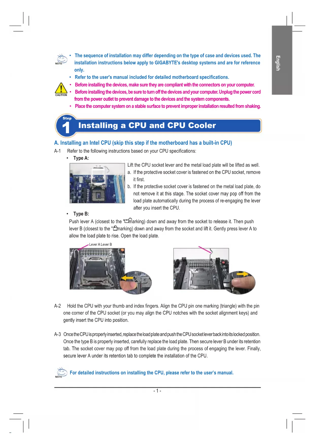
- Type A:
natural_image
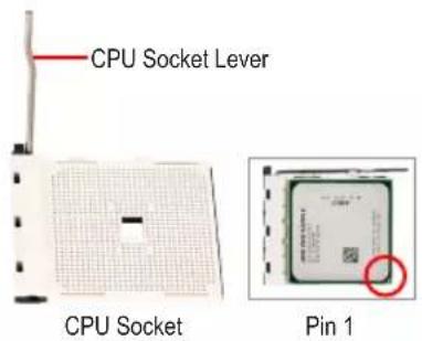
Close-up of a computer motherboard with a highlighted CPU socket and surrounding circuitry (no visible text or symbols)Lift the CPU socket lever and the metal load plate will be lifted as well.
a. If the protective socket cover is fastened on the CPU socket, remove it first.
b. If the protective socket cover is fastened on the metal load plate, do not remove it at this stage. The socket cover may pop off from the load plate automatically during the process of re-engaging the lever after you insert the CPU.
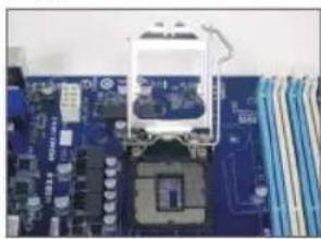
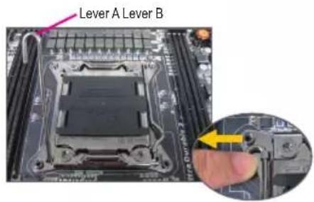
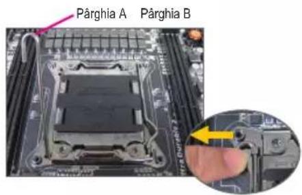
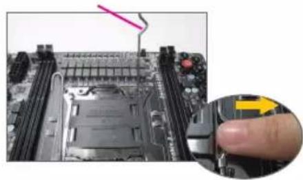
- Type B:
Push lever A (closest to the "marking) down and away from the socket to release it. Then push lever B (closest to the "marking) down and away from the socket and lift it. Gently press lever A to allow the load plate to rise. Open the load plate.
natural_image
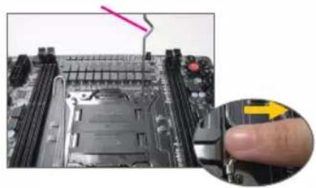
Close-up of a computer motherboard with a finger pressing a button, showing no visible text or symbols.A-2 Hold the CPU with your thumb and index fingers. Align the CPU pin one marking (triangle) with the pin one corner of the CPU socket (or you may align the CPU notches with the socket alignment keys) and gently insert the CPU into position.
A-3 Once the CPU is properly inserted, replace the load plate and push the CPU socket lever back into its locked position. Once the type B is properly inserted, carefully replace the load plate. Then secure lever B under its retention tab. The socket cover may pop off from the load plate during the process of engaging the lever. Finally, secure lever A under its retention tab to complete the installation of the CPU.

For detailed instructions on installing the CPU, please refer to the user's manual.
B. Installing an AMD CPU (skip this step if the motherboard has a built-in CPU)
B-1 Completely raise the CPU socket lever. Align the CPU pin one (small triangle marking) with the triangle marking on the CPU socket and gently insert the CPU into the socket. Make sure that the CPU pins fit perfectly into their holes.
B-2 Once the CPU is positioned into its socket, place one finger down on the middle of the CPU, lowering the socket lever and latching it into the fully locked position.

- Do not force the CPU into the CPU socket. The CPU cannot fit in if oriented incorrectly. Adjust the CPU orientation if this occurs.
- DO NOT touch socket contacts. To protect the CPU socket, always replace the protective socket cover when the CPU is not installed.
C. Installing the CPU Cooler
natural_image
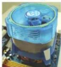
Close-up of a blue CPU fan with heatsink and heatsink head (no visible text or symbols)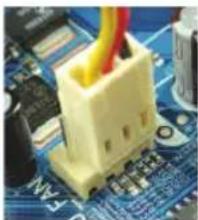
natural_image
Close-up of a yellow plastic connector inserted into a blue circuit board (no visible text or symbols)C-1 Before installing the CPU cooler, please first add a thin layer of heat sink paste on the surface of the CPU. Then install the cooler (refer to the installation manual for your CPU cooler).
C-2 Connect the CPU cooler cable to the CPU_FAN connector located on the motherboard so that the cooler can properly function to prevent the CPU from overheating.

Installing Memory
natural_image
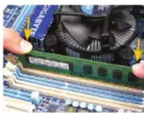
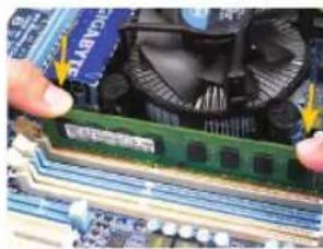
Close-up of hands holding a green RAM module on a computer motherboard with a fan in the background (no visible text or symbols)Note the orientation of the memory module. Spread the retaining clips at both ends of the memory socket. Place the memory module on the socket. As indicated in the picture on the left, place your fingers on the top edge of the memory, push down on the memory and insert it vertically into the memory socket. The clips at both ends of the socket will snap into place when the memory module is securely inserted.

Preparing the Case and Installing a Power Supply
natural_image
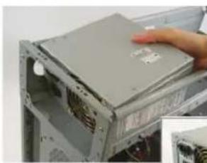
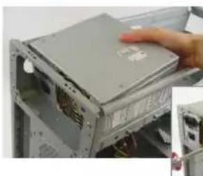
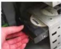
Close-up of a hand pressing down on a computer drive chassis (no visible text or symbols)Using the GIGABYTE desktop system as the demonstration example, please first remove both sides and the lid of the case in order to install the power supply. Place the power supply in the correct place in the case and secure it with screws. Installation and placement of the power supply may differ depending on the type of case used.


To ensure sufficient power can be supplied to your system, it is recommended that a power supply of good quality be used. If a power supply is used that does not provide the required power, the result can lead to an unstable or unbootable system.
Step 4
Installing the Motherboard
natural_image
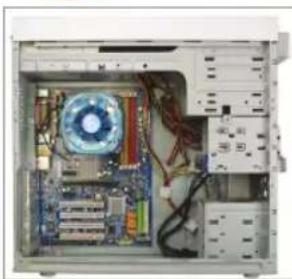
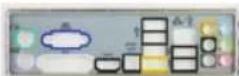
Interior view of a computer tower case showing CPU socket, motherboard, and drive unit (no visible text or labels)Remove the original I/O shield from the back of the case and replace it with the motherboard I/O shield. Place the motherboard within the case by positioning it into its I/O shield. Align the mounting screw holes on the motherboard with their corresponding mounting holes on the case. Secure the motherboard in place with screws.
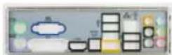
I/O Shield
Step 5
Installing an Expansion Card
natural_image
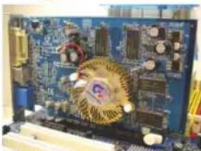
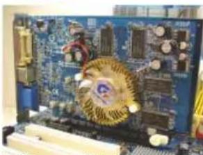
Close-up of a blue circuit board with visible components and a golden circular emblem on the circuit (no text or symbols)PCI Express Graphics Card
Locate an expansion slot that supports your card and remove the slot cover from the case back panel. Then insert the expansion card into the slot. Secure the expansion card's bracket to the case back panel with a screw.

Before purchasing an expansion card, check the length of the card, making sure it can fit into your case.
• Make sure that the expansion card is fully seated in its slot.
Step 6
Installing IDE and SATA Devices
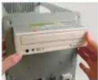
Installing an Optical Drive
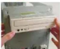
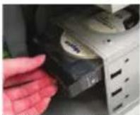
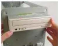
6-1 Install your optical drives, such as DVD-ROM and CD-ROM drives.
Remove the 5.25" drive bay cover from the front of the case. Mount the optical drive in the 5.25" drive bay and secure it with screws.
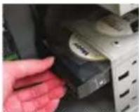
Installing a Hard Drive
6-2 Install your IDE and SATA hard drives.
Install the hard drive into a drive bay within the case and secure it with screws.

- One motherboard IDE connector can connect up to two IDE devices. Prior to installation, check the jumper settings (master and slave) on your IDE devices.
- If more than one hard drive is installed, enter system BIOS Setup to set the hard drive boot sequence.

Connecting Cables to Internal Connectors
7-1 Connect cables to internal connectors and headers on the motherboard, including IDE/SATA connectors, and front panel audio, USB, IEEE 1394 headers, etc.
7-2 Attach the front panel module (differs depending on the case design, consisting of power indicator, hard drive activity indicator, speakers, reset switch, power switch, etc.) from the case to the front panel header (F_PANEL) on the motherboard.
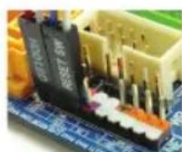
Front Panel Header
Pin Assignments A:
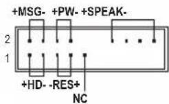
Pin Assignments B:
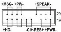
MSG: Message/Power/Sleep LED
PWR: Power LED
PW: Power Switch
SPEAK: Speaker
HD: Hard Drive Activity LED
RES: Reset Switch
CI: Chassis Intrusion Header
(Note) The pin assignments for the front panel header may differ by model. Refer to the motherboard user's manual for the actual pin assignments.

Connecting Peripherals
Back Panel of the Case
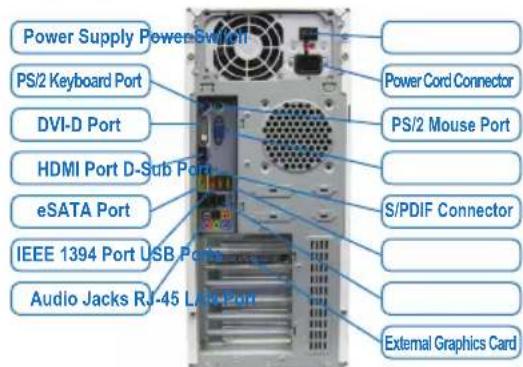
Once the steps above have been completed, connect the peripheral devices to the computer, such as the keyboard, mouse, monitor, etc. Then connect the power, turn on the system, and install all required software.


natural_image
Close-up of a computer motherboard with a white car component and CPU socket (no visible text or symbols)natural_image
Close-up of a computer motherboard with a finger pressing a button (no visible text or symbols)natural_image
Close-up of a blue CPU fan with heatsink and motherboard (no visible text or symbols)
natural_image
Close-up of a yellow electronic component with red wires inserted on a blue circuit board (no visible text or symbols)natural_image
Close-up of hands holding a green CPU socket next to a motherboard with blue circuit lines and a fan (no visible text or symbols)natural_image
Close-up of a hand holding a computer tower case with visible drive bays and cable (no text or symbols)natural_image
Interior view of a computer tower showing CPU socket, motherboard, and drive bays (no visible text or labels)natural_image
Close-up of a computer motherboard with visible circuitry and components (no text or symbols)PCI Express Grafikkarte
natural_image
Close-up of a blue computer motherboard with a white car component (no visible text or symbols)natural_image
Close-up of a computer motherboard with a finger pressing a key (no visible text or symbols)natural_image
Close-up of a blue CPU fan mounted on a motherboard (no visible text or symbols)
natural_image
Close-up of a yellow electronic component with red wires inserted on a blue circuit board (no visible text or symbols)natural_image
Close-up of hands holding a green RAM module with a cooling fan above, placed on a computer motherboard (no visible text or symbols)natural_image
Interior view of a computer tower case showing CPU socket, motherboard, and drive bays (no visible text or labels)natural_image
Close-up of a computer motherboard with visible circuitry and components (no readable text or symbols)natural_image
Close-up of a blue computer motherboard with a white plastic component mounted on top (no visible text or symbols)natural_image
Close-up of a computer motherboard with a finger pressing a button (no visible text or symbols)natural_image
Close-up of a blue CPU fan with heatsink and motherboard (no visible text or symbols)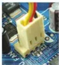
natural_image
Close-up of a yellow electronic component with red wires on a blue circuit board (no visible text or symbols)natural_image
Close-up of hands holding a green RAM module on a computer motherboard with a fan and CPU socket visible (no text or symbols)natural_image
Close-up of a hand holding a computer tower case with visible drive bays and ventilation slots (no text or symbols)natural_image
Interior view of a computer tower case showing CPU socket, motherboard, and drive bays (no visible text or labels)natural_image
Close-up of a computer motherboard with visible circuitry and components (no text or symbols)Placa gráfica PCI Express
natural_image
Close-up of a blue computer motherboard with a white plastic component mounted on top (no visible text or symbols)natural_image
Close-up of a blue CPU fan with heatsink and motherboard (no visible text or symbols)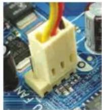
natural_image
Close-up of a yellow electronic component mounted on a blue circuit board with visible traces and components (no text or symbols)natural_image
Close-up of hands holding a green RAM module on a computer motherboard with a blue CPU fan visible (no text or symbols)natural_image
Close-up of a hand holding a silver computer tower case, showing internal components and wiring (no visible text or symbols)natural_image
Interior view of a computer tower showing CPU socket, motherboard, and drive bays (no visible text or labels)natural_image
Close-up of a computer motherboard with visible circuitry and components (no text or symbols)
The Ground Truth image displays a single, solid horizontal line. According to Rule 2 (UNDERSCORE & LINE RULES), this is a stylistic or background line, not a placeholder underscore. Therefore, the OCR result must ignore it and output nothing or only meaningful text. The provided OCR content is "____", which consists of four underscores. This is an incorrect interpretation of the line as a placeholder, violating the rule that stylistic lines must be ignored. The OCR has hallucinated placeholder underscores where none should exist in the GT. Hence, the OCR result is inconsistent with the Ground Truth.
natural_image
Close-up of a blue computer motherboard with visible CPU socket and circuit board (no text or symbols)natural_image
Close-up of a computer motherboard with a finger pressing a button, showing no visible text or symbols.natural_image
Close-up of a blue CPU fan with ventilation slots on a motherboard (no visible text or symbols)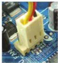
natural_image
Close-up of a yellow plastic electronic component mounted on a blue circuit board (no visible text or symbols)natural_image
Close-up of hands holding a green RAM module on a computer motherboard with a fan in the background (no visible text or symbols)natural_image
Close-up of a hand placing a hard drive into a computer tower case (no visible text or symbols)natural_image
Interior view of a computer tower showing CPU socket, motherboard, and drive bays (no visible text or labels)natural_image
Close-up of a computer motherboard with visible circuitry and components (no text or symbols)natural_image
Close-up of a blue computer motherboard with a white CPU socket and a green tower (no visible text or symbols)natural_image
Close-up of a computer motherboard with a finger pressing a button (no visible text or symbols)natural_image
Close-up of a blue CPU fan on a motherboard (no visible text or symbols)
natural_image
Close-up of a yellow plastic electronic component inserted into a blue circuit board (no visible text or symbols)natural_image
Close-up of hands holding a green RAM module on a computer motherboard with a blue CPU fan visible (no text or symbols)natural_image
Close-up of a computer tower with a hand touching the cover (no visible text or symbols)natural_image
Interior view of a computer tower case showing CPU socket, motherboard, and drive unit (no visible text or labels)natural_image
Close-up of a computer motherboard with visible circuitry and components (no readable text or symbols)natural_image
Close-up of a blue computer motherboard with a white plastic component inserted, no visible text or symbolsnatural_image
Close-up of a computer motherboard with a finger pressing a button (no visible text or symbols)natural_image
Close-up of a blue CPU fan mounted on a motherboard (no visible text or symbols)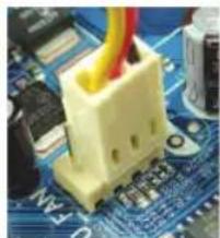
natural_image
Close-up of a yellow electronic component mounted on a blue circuit board (no visible text or symbols)natural_image
Close-up of hands holding a green CPU socket next to a blue CPU board with a fan, no visible text or symbolsnatural_image
Close-up of a hand holding a computer tower case with visible drive bays and ventilation slots (no text or symbols)natural_image
Interior view of a computer tower case showing CPU socket, motherboard, and drive bays (no visible text or labels)natural_image
Close-up of a computer motherboard with visible circuitry and components (no text or symbols)natural_image
Close-up of a computer motherboard with CPU socket and circuit board (no visible text or symbols)natural_image
Close-up of a computer motherboard with a finger pressing a button (no visible text or symbols)
natural_image
Close-up of a blue CPU fan with heatsink and motherboard (no visible text or symbols)
natural_image
Close-up of a yellow electronic component with red wires on a blue circuit board (no visible text or symbols)natural_image
Close-up of hands holding a green RAM module with a CPU fan in the background (no visible text or symbols)natural_image
Close-up of a hand placing a computer drive into a hard drive chassis (no visible text or symbols)natural_image
Interior view of a computer tower showing CPU socket, motherboard, and drive bays (no visible text or labels)natural_image
Close-up of a computer motherboard with visible circuitry and components (no text or symbols)natural_image
Close-up of a computer motherboard with a CPU socket and a white plastic component (no visible text or symbols)Push lever A (closest to the "marking) down and away from the socket to release it. Then push lever B (closest to the "marking) down and away from the socket and lift it. Gently press lever A to allow the load plate to rise. Open the load plate.
natural_image
Close-up of a computer motherboard with a finger pressing a button (no visible text or symbols)A-2 Hold the CPU with your thumb and index fingers. Align the CPU pin one marking (triangle) with the pin one corner of the CPU socket (or you may align the CPU notches with the socket alignment keys) and gently insert the CPU into position.
natural_image
Close-up of a blue CPU fan resting on a motherboard (no visible text or symbols)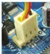
natural_image
Close-up of a yellow electronic component with red wires on a blue circuit board (no visible text or symbols)natural_image
Close-up of hands holding a green RAM module with a fan in the background (no visible text or symbols)natural_image
Close-up of a hand holding a computer tower case with visible drive bays and cable (no text or symbols)natural_image
Interior view of a computer tower case showing CPU socket, motherboard, and drive bays (no visible text or labels)natural_image
Close-up of a computer motherboard with visible circuitry and components (no text or symbols)HD: LED activate hard disk
natural_image
Close-up of a computer motherboard with a CPU socket and surrounding electronic components (no visible text or symbols)natural_image
Close-up of a computer motherboard with a finger pressing a button, showing no visible text or symbols.natural_image
Close-up of a blue CPU fan on a motherboard (no visible text or symbols)
natural_image
Close-up of a yellow electronic component mounted on a blue circuit board with visible traces and components (no text or symbols)natural_image
Close-up of hands holding a green RAM module with a fan and cooling fan in the background (no visible text or symbols)natural_image
Close-up of a hand pressing down on a computer tower case (no visible text or symbols)natural_image
Interior view of a computer tower showing CPU socket, motherboard, and drive bays (no visible text or labels)natural_image
Close-up of a computer motherboard with visible circuitry and components (no readable text or symbols)natural_image
Close-up of a computer motherboard with CPU socket and surrounding components (no visible text or symbols)natural_image
Close-up of a computer motherboard with a finger pressing a key (no visible text or symbols)natural_image
Close-up of a blue CPU fan on a motherboard (no visible text or symbols)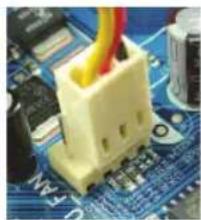
natural_image
Close-up of a yellow plastic electronic component with red wires, placed on a blue circuit board (no visible text or symbols)natural_image
Close-up of hands holding a green RAM module with a CPU fan in the background (no visible text or symbols)natural_image
Interior view of a computer tower showing CPU socket, motherboard, and drive bays (no visible text or labels)natural_image
Close-up of a computer motherboard with visible circuitry and components (no text or symbols)PCI Express videokártya
natural_image
Close-up of a computer motherboard with a CPU socket and a highlighted component (no visible text or symbols)natural_image
Close-up of a computer motherboard with a finger pressing a button (no visible text or symbols)natural_image
Close-up of a blue CPU cooler with heatsink on a motherboard (no visible text or symbols)
natural_image
Close-up of a yellow electronic component mounted on a blue circuit board (no visible text or symbols)natural_image
Close-up of hands holding a green RAM module on a computer motherboard with a fan in the background (no visible text or symbols)natural_image
Close-up of a hand holding a gray computer tower case with visible drive bays and ventilation slots (no text or symbols)natural_image
Interior view of a computer tower case showing CPU socket, motherboard, and drive bays (no visible text or labels)natural_image
Close-up of a computer motherboard with visible circuitry and components (no readable text or symbols)natural_image
Close-up of a computer motherboard with CPU socket and motherboard (no visible text or symbols)natural_image
Close-up of a computer motherboard with a finger pressing a button (no visible text or symbols)natural_image
Close-up of a blue CPU socket mounted on a motherboard (no visible text or symbols)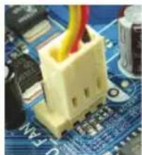
natural_image
Close-up of a yellow electronic component mounted on a blue circuit board with visible traces and components (no text or symbols)natural_image
Close-up of hands holding a green RAM module on a computer motherboard with a fan in the background (no visible text or symbols)natural_image
Close-up of a hand holding a gray computer case with visible drive bays and circuitry (no text or symbols)natural_image
Interior view of a computer tower case showing CPU socket, motherboard, and drive bays (no visible text or labels)natural_image
Close-up of a computer motherboard with visible circuitry and components (no readable text or symbols)natural_image
Close-up of a computer motherboard with a central CPU socket and a small white electronic component (no visible text or symbols)natural_image
Close-up of a computer motherboard with a finger pressing a button, showing no visible text or symbols.A-2 Držite procesor palcem i kažiprstom. Poravnajte oznaku prve nožice procesora (trougao) sa uglom za čiodu jedan na podnožju procesora (ili možete da poravnate žlebove procesora sa oznakama za poravnavanje podnožja) i pažljivo ubacite procesor na mesto.
A-3 Jednom kada je procesor ispravno postavljen, spustite pločicu za opterećivanje i gurnite ručicu za podnožje procesora natrag u položaj za blokiranje.
Jednom kada je tip B ispravno ubačen, pažljivo postavite pločicu za pritiskanje. Potom zategnite i zaključajte polugu B ispod njenog zateznog jezička. Poklopac podnožja može da se otkači sa pločice za pritiskanje tokom procesa zatezanja polugice. Na kraju, zategnite i zaključajte polugu A ispod njenog zateznog jezička da završite instaliranje procesora.

Detaljna uputstva za montiranje procesora potražite u korisničkom priručniku.
natural_image
Close-up of a blue CPU fan with heatsink and motherboard (no visible text or symbols)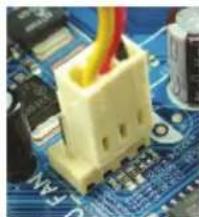
natural_image
Close-up of a yellow fuse component inserted into a blue circuit board (no visible text or symbols)natural_image
Close-up of a computer motherboard with a green CPU socket and a fan, no visible text or symbolsObratite pažnju na to kako je okrenut memorijski modul. Raširite klipove koji drže memoriju sa obe strane podnožja za memoriju. Smestite memorijski modul u podnožje. Kako je prikazano na slici levo, stavite prste na vrh memorije, pritisnite memoriju i ubacite je vertikalno u podnožje za memoriju. Klipovi sa obe strane podnožja će se vratiti na mesto kada je memorijski modul ispravno ubačen.

Priprema kućišta i instaliranje napajanja
natural_image
Close-up of a hand holding a computer tower case with visible internal components (no text or symbols)natural_image
Interior view of a computer tower showing CPU socket, motherboard, and drive bays (no visible text or labels)Uklonite originalni I/O štit sa poledine kućišta i zamenite ga I/O štitom matične ploče. Stavite matičnu ploču u kućište smeštajući je na svoj I/O štit. Poravnajte rupice za montiranje na matičnoj ploči sa odgovarajućim rupicama za montiranje na kućištu. Pričvrstite matičnu ploču na mesto šrafovima.
I/O štit
Korak 5
Instaliranje dodatnih kartica

natural_image
Close-up of a computer motherboard with visible circuitry and components (no readable text or symbols)Pronađite određeni port (slot) koji podržava vašu karticu i uklonite poklopac porta (slota) sa zadnje strane kućišta. Potom ubacite karticu u port (slot). Pričvrstite spoj ekspanzione kartice za poledinu kućišta šrafom.
PCI EXpress grafička kartica

- Pre kupovine ekspanzione kartice, proverite dužinu kartice da bi bili sigurni da može da stane u kućište.
• Proverite da li je grafička kartica potpuno ulegla u prorez.
Korak 6
Instaliranje IDE i SATA uređaja
Instaliranje optičkog uređaja
6-1 Instalirajte svoje optičke uređaje, poput DVD-ROM i CD-ROM uređaja.
Uklonite poklopac za prorez uređaja veličine 5.25" sa prednje strane kućišta.
Ubacite optički uređaj veličine 5.25" u rupu i pričvrstite ga šrafovima.
Instaliranje hard diska
6-2 Instalirajte svoje IDE i SATA hard diskove. Instalirajte hard disk u prostor za hard disk u kućištu i pričvrstite ga šrafovima.

- Jedan IDE konektor na matičnoj ploči može da poveže do dva IDE uređaja. Pre instalacije, proverite kako su podešeni džamperi (master i slejv) na vašim IDE uređajima.
- Ukoliko ste instalirali više od jednog hard diska, udite u BIOS podešavanja da bi odredili redosled podizanja hard diskova.
Korak 7
Povezivanje Kablova na Interne Konektore
7-1 Povežite kablove za unutrašnje konektore i zaglavlja na matičnoj ploči, uključujući IDE/SATA konektore i audio prednjeg panela, USB, IEEE 1394 zaglavlja itd.
7-2 Pričvrstite modul prednjeg panela (razlikuje se u zavisnosti od dizajna kućišta i sastoji se od indikatora napajanja, indikatora aktivnosti hard diska, zvučnika, prekidača za resetovanje, prekidača za uključivanje itd.) sa kućišta za zaglavlje prednjeg panela (F_PANEL) na matičnoj ploči.
natural_image
Close-up of a blue computer motherboard with a white plastic component mounted on top (no visible text or symbols)natural_image
Close-up of a computer motherboard with a finger pressing a button (no visible text or symbols)A-2 Uhvatite procesor između kažiprsta i palca. Poravnajte (trokutastu) oznaku kontakta broj jedan s kutom kontakta jedan na podnožju (ili možete poravnati usjeke procesora s ključevima poravnavanja) i blago gurnite procesor na svoje mjesto.
A-3 Kad procesor ispravno ugrađen, vratite ugradbenu ploču i gurnite ručicu podnožja procesora u blokirani položaj. Kad ste propisno umetnuli vrsta B, pažljivo vratite pločicu za umetanje. Zatim pričvrstite ručicu B ispod jezička za osiguranje. Poklopac podnožja možda će odskočiti s pločice za umetanje za vrijeme postupka zaglavljivanje ručice. Na kraju, pričvrstite ručicu A ispod svog jezička za fiksiranje i završite ugradnju procesora.

Detaljne upute o instaliranju procesora potražite u korisničkom priručniku.
natural_image
Close-up of a blue CPU socket mounted on a motherboard (no visible text or symbols)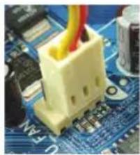
natural_image
Close-up of a yellow industrial component with red wires on a blue circuit board (no visible text or symbols)C- 1 Prije ugradnje hladnjaka procesora, premažite procesor tankim slojem termovodljive paste. Zatim ugradnje hladnjak (pogledajte priručnik za ugradnje hladnjaka procesora).
C- 2 Spojite kabel hladnjaka procesora na CPU_FAN priključak na matičnoj ploči, kako bi hladnjak radio ispravno i kako ne bi došlo do pregrijavanja procesora..

Instalacija memorije
natural_image
Close-up of hands holding a green CPU socket next to a motherboard with cooling fans (no visible text or symbols)Zapamtite usmjerenje memorijskog modula. Raširite kopče na obje strane memorijske utičnice. Umetnite memorijski modul u utičnicu. Kako je prikazano na slici lijevo, postavite svoje prste na vrh memorije, gurnite je prema dolje i umetnite je vertikalno u memorijsku utičnicu. Kopče na oba kraja utičnice će uskočiti na mjesto kad memorijski modul sjedne čvrsto na svoje mjesto.

natural_image
Close-up of a hand holding a computer tower case with visible drive bays and ventilation slots (no text or symbols)natural_image
Interior view of a computer tower showing CPU socket, motherboard, and drive bays (no visible text or labels)Skinite originalni poklopac I/O sa stražnje strane kućišta i zamijenite ga poklopcem matične ploče I/O. Postavite matičnu ploču unutar kućišta, tako da je pozicionirate u I/O štitniku. Poravnajte rupe vijaka za ugradnju na matičnoj ploči s odgovarajućim rupama za montažu na kućištu. Vijcima pričvrstite matičnu ploču na njeno mjesto.

I/O štitnik
Korak 5
Instaliranje kartice za proširenje
natural_image
Close-up of a computer motherboard with visible circuitry and components (no text or symbols)Pronađite utor za proširenje koji podržava vašu karticu i skinite poklopac utora sa stražnje strane kućišta. Zatim umetnite karticu za proširenje u utor. Pričvrstite nosač kartice za proširenje na stražnju ploču kućišta pomoću vijka.
PCI Express grafička kartica

- Prije nego kupite karticu za proširenje, provjerite duljinu kartice i da li stane u kućište.
- Provjerite je li kartica za proširenje u potpunosti sjela u utor.
Korak 6
Instaliranje IDE i SATA uređaja
Instaliranje optičkog uređaja
6-1 Instalirajte optičke uređaje kao što su DVD-ROM i CD-ROM. Izvadite ležište za 5,25" pogon s prednje strane kućišta. Ugradite optički pogon u ležište uređaja 5,25" i stegnite ga vijcima.
Instaliranje hard diska
6-2 Instalirajte IDE i SATA uređaje hard diska. Instalirajte hard disk u ležište uređaja s kućištem i stegnite ga vijcima.

- Jedan priključak na matičnoj ploči može se spojiti na dva IDE uređaja. Prije instalacije, provjerite postavke premosnika (glavni i sporedni) na vašim IDE uređajima.
- Ako instalirate više od jednog hard diska, uđite u BIOS Setup (BIOS postavke) i podesite redoslijed pokretanja računala.

natural_image
Interior view of a computer tower showing CPU socket, motherboard, and drive bays (no visible text or labels)(I/O shield)
תְרָה לַעֹלְרָה
5
natural_image
Close-up of a computer motherboard with visible circuit boards and a central golden spiral component (no text or symbols)natural_image
Close-up of a blue industrial fan or compressor unit mounted on a CPU socket (no visible text or symbols)
natural_image
Close-up of a yellow plastic connector with red wires inserted into it, placed on a blue circuit board (no visible text or symbols)תְרָה בַרִי
2
natural_image
Close-up of hands holding a green CPU socket next to a motherboard with a blue fan and blue drive vane (no visible text or symbols)natural_image
Close-up of a computer tower case with visible cooling fans and a hand adjusting the cover (no text or symbols)natural_image
Close-up of a computer motherboard with a white plastic component mounted on top (no visible text or symbols):В аю •