B 110 R Classic - Industrial floor scrubber Kärcher - Free user manual and instructions
Find the device manual for free B 110 R Classic Kärcher in PDF.

| Product type | Industrial scrubber dryer with driver seat |
| Brand | Kärcher |
| Model | B 110 R Classic |
| Cleaning head | R (roller) or D (disc) depending on version |
| Dimensions (L x W x H) | 1660 x 1035 x 1480 mm |
| Empty weight | 380 kg |
| Typical operating weight | 590 kg |
| Maximum permissible weight | 720 kg |
| Rated voltage | 24 V |
| Battery capacity | 170 Ah (5 h) |
| External charger | 230 V, 50-60 Hz, 50 A |
| Fresh water tank volume | 130 L |
| Dirty water tank volume | 110 L |
| Coarse dirt tank volume | 1.8 L (R head) |
| Working width | 750 mm |
| Suction bar width | 1000 mm |
| Theoretical area performance | 4500 m²/h |
| Practical area performance | 3150 m²/h |
| Driving/cleaning speed | 6 km/h |
| Transport speed | 6 km/h |
| Reverse speed | 4 km/h |
| Max inclination working area | 10 % |
| Short distance inclination (max 10 m) | 22 % |
| Sound pressure level (normal) | 63.6 dB(A) |
| Sound power level (normal) | 78.7 dB(A) |
| Operating temperature | +5 °C to +40 °C |
| Max water temperature | 50 °C |
| Protection type | IPX3 |
| Main functions | Water cleaning, polishing, suction, brushing |
| Safety | Safety switch, seat switch, thermal protection |
| Maintenance and cleaning | Cleaning filters, suction lips, brushes, draining tanks |
| Spare parts and repairability | Brushes, suction lips, filters, batteries, charger |
Frequently Asked Questions - B 110 R Classic Kärcher
User questions about B 110 R Classic Kärcher
0 question about this device. Answer the ones you know or ask your own.
Ask a new question about this device
Download the instructions for your Industrial floor scrubber in PDF format for free! Find your manual B 110 R Classic - Kärcher and take your electronic device back in hand. On this page are published all the documents necessary for the use of your device. B 110 R Classic by Kärcher.
USER MANUAL B 110 R Classic Kärcher
natural_image
Line drawing of a cleaning or inspection machine with control panel and wheels (no text or symbols)Deutsch 3
English 12
Français 22
Italiano 32
Español 42
Português 53
Nederlands 62
Türkçe 72
Svenska 82
Suomi 92
Norsk 102
Dansk 112
Eesti 122
Latviešu 132
Lietuviškai 142
Polski 152
Magyar 163
Čeština 172
Slovenčina 182
Slovenščina 192
Românește 202
Hrvatski 212
Srpski 222
Ελληνικά 232
Русский 243
Українська 254
Български 265
中文 276
日本語 286
한국어 295
العربية 315
Inhalt
①Hupe
①Spannband ②Brett
③Klotz
④Kantholz
natural_image
Technical line drawing of a mechanical lift or platform with no visible text or symbols①Entriegslungshebel
natural_image
Technical line drawing of a mechanical assembly with pulleys and wheels (no text or symbols)①Schraube
②Mutter
③Wasserwage
natural_image
Diagram of a hand holding a flexible hose with directional arrows indicating movement or force (no text or symbols present)Lagerung
△VORSICHT
① Schwimmer
O
Chairman of the Board of Management
S. Reiser
Director Regulatory Affairs & Certification
71364 Winnenden (Germany)
Tel.: +49 7195 14-0
Fax: +49 7195 14-2212
Winnenden, /09/01
Contents
General notes 12
Function 12
Intended use 12
Environmental protection 12
Accessories and spare parts.... 13
Scope of delivery 13
Safety instructions.... 13
Description of the unit 14
Installation 15
Initial startup.... 16
Operation 16
Finishing operation.... 17
Grey Intelligent Key 17
Transport 18
Storage 18
Care and maintenance.... 18
Troubleshooting guide.... 19
Warranty.... 20
Accessories.... 20
Technical data 21
Declaration of Conformity 22
General notes

Read these original operating instruc-
tions and the enclosed safety instruc-
tions before using the device for the first
time. Proceed accordingly.
Keep both books for future reference or for future owners.
Function
This scouring and vacuum machine is used for wet cleaning or polishing of level floors.
The device can be adjusted to suit the respective cleaning task by setting the water volume and detergent volume appropriately.
The working width and the capacity of the fresh and waste water tanks (see chapter "Technical data") enable effective cleaning with a long working time.
The device has a drive motor.
Note
The device can be equipped with various accessories to suit the respective cleaning task. Request a copy of our catalogue or visit our Internet website at www.kaercher.com.
Intended use
This device is suitable for commercial and industrial use, e.g. in hotels, schools, hospitals, factories, shops, offices, and rental companies. Use the device only in accordance with the information in these operating instructions.
- The device may only be used for cleaning smooth surfaces that are insensitive to water and polishing.
- The device is designed for indoor use.
- The operational temperature range is between +5 °C and +40 °C.
- The device is not suitable for cleaning frozen floors (e.g. in cold stores).
- The device is suitable for a maximum water height of 1 cm. Do not drive into an area if there is a danger of exceeding the maximum water height.
- When using chargers or batteries, only the components approved in the operating instructions may be used. A different combination must be confirmed by the responsible charger and/or battery supplier.
- The device is not intended for cleaning public traffic routes.
- The device must not be used on pressure-sensitive floors. Take into account the permissible load per unit area of the floor. The load per unit area caused by the device is specified in the technical data.
- The device is not suitable for use in potentially explosive environments.
- The device is approved for operation on surfaces with a maximum slope (see chapter "Technical Data").
Environmental protection
The packing materials can be recycled. Please dispose of packaging in accordance with the environmental regulations.
Electrical and electronic devices contain valuable, recyclable materials and often components such as batteries, rechargeable batteries or oil,
which - if handled or disposed of incorrectly - can pose a potential danger to human health and the environment. However, these components are required for the correct operation of the device. Devices marked by this symbol are not allowed to be disposed of together with the household rubbish.
Notes on the content materials (REACH)
Current information on content materials can be found at: www.kaercher.de/REACH
Accessories and spare parts
Only use original accessories and original spare parts.
They ensure that the appliance will run fault-free and safely.
Information on accessories and spare parts can be found at www.kaercher.com.
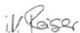
Scope of delivery
Check the contents for completeness when unpacking.
If any accessories are missing or in the event of any shipping damage, please notify your dealer.
Safety instructions
Before using the device for the first time, read and observe these operating instructions and the accompanying brochure: Safety instructions for brush cleaning devices, No. 5.956-251.0.
The device is approved for operation on surfaces with a specified limited slope (see chapter "Technical Data").
△WARNING
The device can tip over
Risk of injury
Only operate the device on surfaces that do not exceed the permitted slope (see chapter "Technical Data").
△WARNING
Risk of accident due to incorrect operation
People can be injured.
Operators must be properly trained on how to use this machine.
The device may only be operated when the hood and all covers are closed.
Safety devices
△CAUTION
Missing or modified safety devices!
Safety devices are provided for your own protection.
Do not bypass, remove or render ineffective any safety devices.
Safety switch
For immediate shutdown of all functions: Set the safety switch to "0".
- The device brakes hard when the safety switch is switched off.
- The safety switch acts directly on all device functions
Seat switch
If the operator leaves the seat during work or while driving, the seat switch switches off the engine after a short delay.
Symbols on the device

ATTENTION
Risk of damage
Water will damage the suction turbine.
Do not fill or splash water into this opening.

△CAUTION
Danger of burns
Components marked with this notice become
hot during operation.
Do not touch components marked in this way. Let these components cool down before working on the device.

△DANGER
Danger of accident
On slopes, there is an increased risk of tipping
over at high speed.
Drive slowly downhill.
Do not turn on a slope.
When driving fast, avoid jerky steering with a large
steering angle.
Warning symbols
Observe the following warnings when handling the batteries:

Observe notes in the instructions for the battery, on the battery and in these operating instructions.

Wear eye protection.

Keep acids and batteries away from children.
Risk of explosion
Fire, sparks, open flames and smoking are prohibited.
Risk of acid burns

First aid.

Warning

Disposal
Do not throw batteries in the bin.
Description of the unit
Overview of the device
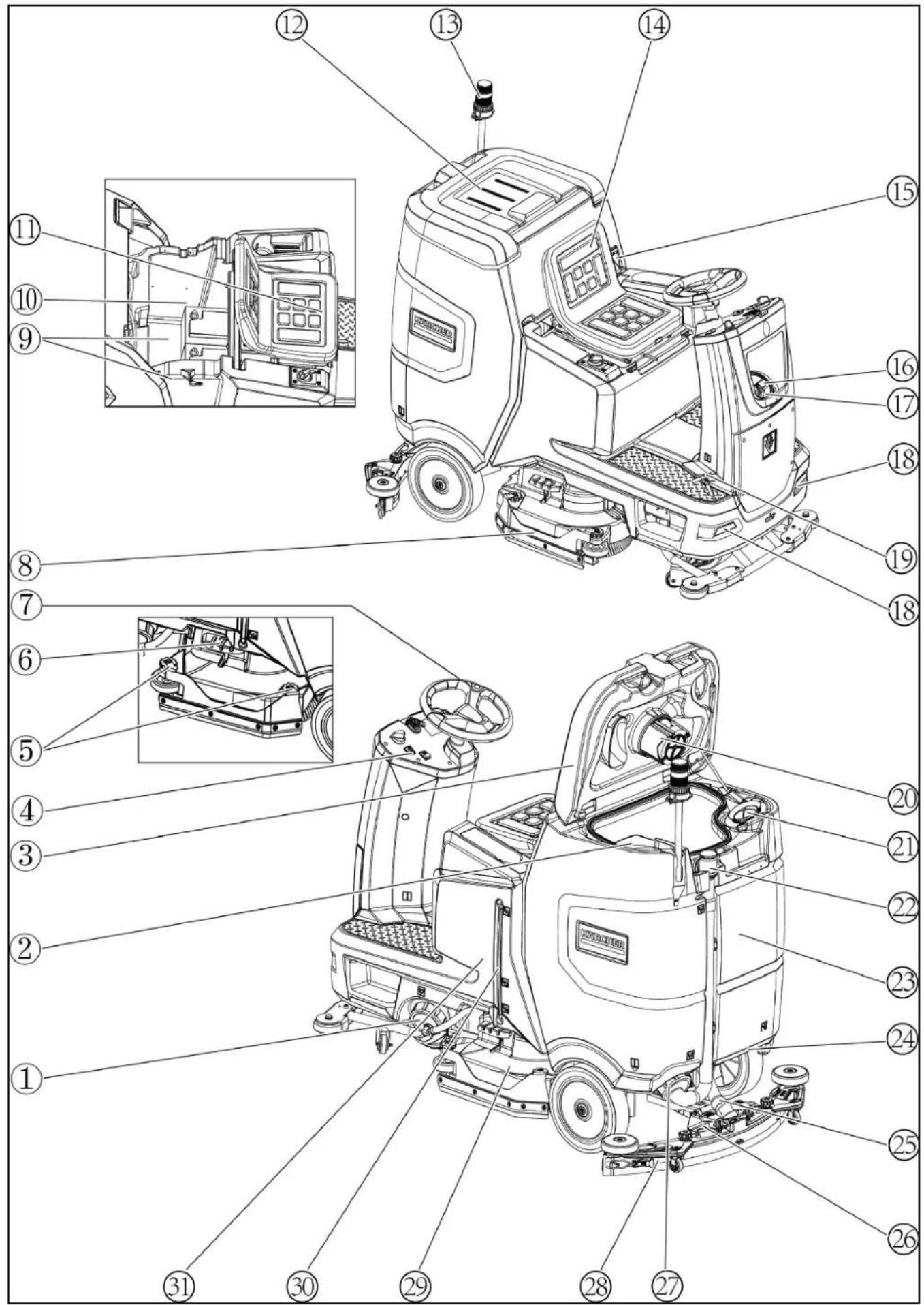
① Fresh water tank cap with fresh water filter
② Coarse dirt filter
③ Waste water tank cap
④ Control panel
⑤ Squeegee blade adjustment wheel (D cleaning head only)
⑥Brush replacement pedal
⑦ Steering wheel
⑧ Side skirts
⑨*Battery
10Type plate
⑪ Seat adjustment lever
⑫Storage area for "Homebase Box" cleaning set
⑬*Warning light
⑭Seat
⑮ Waste water tank latch
⑯ Fresh water tank filling hole
⑰Hose holder
⑱Daytime running light
⑲ Accelerator pedal
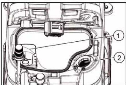
20Float
21Fluff filter
②2 Waste water tank drain hose
23 Waste water tank
24* Mop holder
25 Suction hose
26 Suction bar clamping lever
27 Waste water tank cap
28 Suction bar
29 Cleaning head
30 Fresh water filling level indicator
31 Fresh water tank
* optional
Colour coding
- Control elements for the cleaning process are yellow.
- Control elements for maintenance and servicing are light grey.
Control panel
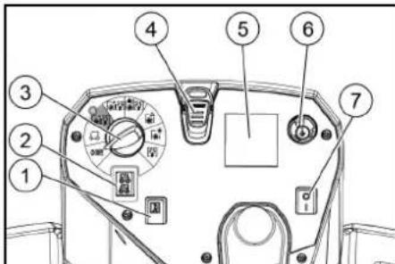
① Horn
② Travel direction switch
③Program switch
④Intelligent Key
⑤*Display
⑥Info button
⑦ Safety switch
*Disturbances in the symbols on the display can be caused by the influence of electromagnetic devices such as mobile phones, but have no effect on the operating behavior.
Program switch
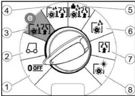
①OFF
Device is switched off.
②TRANSPORT MODE
Drive to the operating location.
③ ECO MODE
Clean the floor wet (with a reduced amount of water and a reduced brush speed) and vacuum up waste water (with reduced suction power).
④NORMAL MODE
Clean the floor wet and vacuum up waste water.
⑤HEAVY MODE
Clean the floor wet (with increased brush contact pressure) and vacuum up waste water.
⑥SCRUB MODE
Precleaning without vacuuming
Clean the floor wet and let the detergent act.
⑦ SUCTION MODE
Vacuum up the dirty waste.
⑧ POLISH MODE
Polish the floor at a high brush speed without applying liquid.
Symbols on the device

Fresh water tank drain opening
Waste water tank drain opening

Fresh water tank filling level (50%)

Lashing point

* Mop holder

Brush replacement

* optional
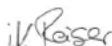
Installation
Unloading
-
Remove the packaging film.
-
Remove the strap.
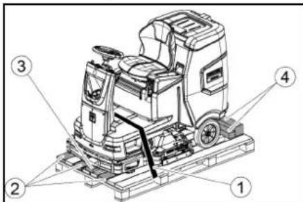
①Strap
②Board
③Block
④Beam
-
Unscrew the block, squared timber and boards. The components to be unscrewed are marked in grey in the figure.
-
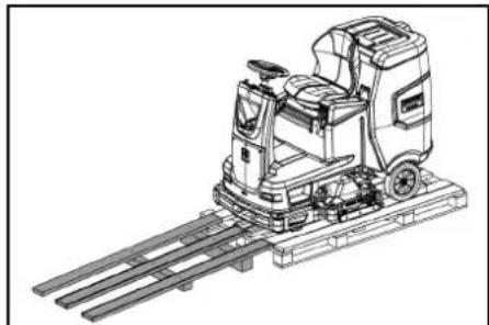
Place a ramp in front of the pallet with the un-screwed boards and squared timber and fasten with chipboard screws.
-
Unscrew the block, squared timber and boards. The components to be unscrewed are marked in grey in the figure.
- Place a ramp in front of the pallet with the unscrewed boards and squared timber and fasten with chipboard screws.
natural_image
Technical line drawing of a cleaning or inspection machine on a platform (no text or symbols visible)-
Install the batteries if the device was delivered without batteries (see chapter "Before initial startup/batteries").
-
Drive the device forward and off the pallet (see chapter "Operation / Driving").
Installing the brushes
- The installation of the brushes is described in the chapter "Maintenance work".
Installing the suction bar
- Pivot both clamping levers upwards.
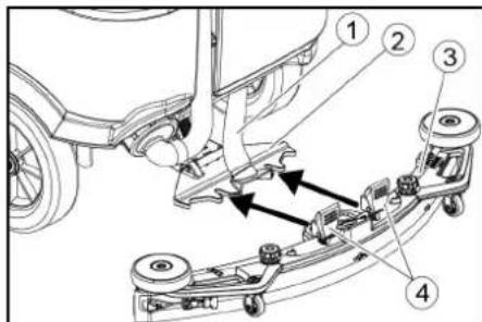
① Suction hose
② Suction bar suspension
③Suction bar
④Clamping lever
-
Insert the suction bar in the suction bar mount.
-
Pivot both clamping levers downwards.
Batteries
Installing and connecting batteries
△CAUTION
Removing and installing the batteries
Unstable machine position
Ensure that the machine is positioned stably when removing and installing the batteries.
ATTENTION
Incorrect connection polarity
Destruction of the control electronics
Take care to ensure the correct polarity when connecting the batteries.
ATTENTION
Deep discharge
Risk of damage
Charge the batteries before starting the device.
-
Drain the waste water.
-
Unlock the waste water tank and pivot it up.
-
Disconnect the seat switch and remove the seat.
-
Place the battery in the device.
-
Connect the device-side battery connector to the battery-side battery connector.
-
Reset the seat and connect the seat switch.
-
Pivot the waste water tank forwards and close it.
Removing the battery
△CAUTION
Removing and installing the batteries
Unstable machine position
Ensure that the machine is positioned stably when removing and installing the batteries.
1. Set the safety switch to "0".
2. Drain the waste water.
3. Unlock the waste water tank and pivot it up.
4. Pull out the battery plug.
- Disconnect the cable from the minus terminal at the battery.
- Disconnect the remaining cables from the battery.
- Remove the battery.
- Dispose of the used batteries in accordance with statutory provisions.
Initial startup
Charging the battery
△DANGER
Inappropriate use of the charger
Electric shock
Adhere to the mains voltage and fuse values specified on the device type plate.
Only use the charger in dry rooms with sufficient ventilation.
Flammable gases are generated when the battery is charged
Risk of explosion
Only charge the battery in a suitable room. The room must have a minimum volume depending on the battery type and an adequate air exchange rate with a minimum air flow (see "Recommended batteries").
ATTENTION
Accumulation of dangerous gases under the tank during the charging process
Risk of explosion
Pivot the waste water tank upwards before charging low-maintenance batteries.
The average charging time is approx. 10-15 hours.
The device cannot be used during the charging process.
Note
The device has deep discharge protection, i.e. the brush motor and turbine are switched off automatically when the permitted minimum capacity level is reached.
- Drive the device directly to the charger and do not drive on slopes.
External charger
ATTENTION
Risk of damage due to unsuitable charger!
Do not connect the charger to the device-side battery connector.
Use only a charger suitable for the type of battery installed.
Battery Capacity Charger
4.039-352.7 170 Ah 6.654-436.0
- Unlock the waste water tank and pivot it up.
- Pull out the device-side battery connector.
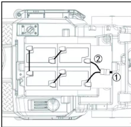
①Battery plug, device side
② Battery plug, battery side
3. Connect the battery-side battery connector to the charger.
4. Plug the mains plug of the charger into the socket.
5. Carry out the charging process in accordance with the operating instructions for the charger.
6. Connect the device-side battery connector to the battery-side battery connector.
7. Pivot the waste water tank forwards and then close it.
Low-maintenance batteries (wet batteries)
△DANGER
Refilling discharged batteries with water
Danger of acid burns from escaping acid, destruction of clothing
Wear safety goggles, protective clothing and protective gloves when handling the battery acid.
Observe the applicable regulations.
Immediately rinse off any splashed acid from the skin or clothing using copious amounts of water.
ATTENTION
Using water with additives
Defective batteries, loss of warranty eligibility
Top up the batteries using only distilled or desalinated water (EN 50272-T3).
Do not use any foreign additives, so-called enhancing agents, because this will invalidate the warranty.
- Add distilled water one hour before the charging process comes to an end. Observe the correct acid level according to the battery label.
All cells must produce gas at the end of the charging process.
- Clean up any spilled water. To do this, proceed as described in the Care and maintenance chapter in the "Cleaning the batteries" section.
Operation
△DANGER
Falling objects
Risk of injury
Do not drive the device into areas where there is a possibility of the operating personnel being hit by falling objects.
ATTENTION
Risks during operation
Risk of injury
In the event of danger, set the safety switch to "0".
Pushing the device
To push the device, the brake must be unlocked.
△DANGER
Danger of accident
When the brake is unlocked, the function of the brake is permanently out of operation.
Be sure to remove the coins for unlocking immediately after the sliding process has ended.
- Swing the unlocking lever away from the wheel and hold it there.
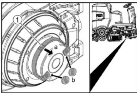
① Unlocking lever
- Insert a coin between the casing and the lever at both ends of the lever.
- Release the unlocking lever.
- Push the device.
- Remove both coins immediately after pushing.
Adjusting the seat
Adjusting the position
- Operate the seat adjustment lever and move the seat to the desired position.
- Release the seat adjustment lever and latch the seat into position.
Switching the device on
- Sit in the driver's seat.
- Insert the Intelligent Key.
- Set the safety switch to "1".
- Turn the program switch to the desired function.
- If one of the displays below appears on the display, take your foot off the accelerator pedal, set the safety switch to "0" and carry out the necessary maintenance work.
| Display Activity | |
| maintenance squeegee | Clean the suction bar. |
| maintenance brush head | Check the brushes for wear and clean them. |
| maintenance squeegee blade | Check the suction lips for wear and correct adjustment. |
| maintenance turbine filter | Clean the fluff filter. |
| maintenance fresh water filter | Clean the fresh water filter. |
-
Press the Info button.
-
Reset the counter for the corresponding maintenance (see "Grey Intelligent Key / Reset maintenance counter").
Note
If the counter is not reset, the maintenance display appears again each time the device is switched on.
Switching on the light
Daytime running light
The daytime running light is in operation when the device is switched on.
Checking the parking brake
△DANGER
Defective parking brake
Danger of accident
Before each operation, check the function of the parking brake on level ground.
- Switch the device on.
- Set the travel direction switch to "Forward"
- Set the program selector switch to "TRANSPORT MODE".
- Press the accelerator pedal lightly.
The brake must audibly unlock. The appliance must roll easily on a plane surface.
- Release the accelerator pedal.
The brake must be audibly engage.
If this is not the case, take the device out of operation and call Customer Service.
Driving
△DANGER
Lack of braking
Danger of accident
Before using the device, it is essential to check the function of the parking brake. Never use the device if the parking brake does not work.
△DANGER
Careless driving
Danger of tipping over
Only drive up and up gradients in the direction of travel and across the direction of travel 10%.
Do not turn up or down gradients.
Drive slowly in corners and on wet ground.
Only drive the device on stable ground.
Note
The travel direction can be changed while driving. This means that very dull spots can be polished by moving back and forth several times.
-
Assume a seated position.
-
Insert the Intelligent Key.
-
Turn the safety switch to "1".
-
Set the program selector switch to "TRANSPORT MODE".
-
Set the direction of travel using the drive direction button on the control panel.
-
Specify the travel speed by pressing the accelerator pedal.
-
Release the accelerator pedal
The device stops.
The driving motor is switched off in the event of an overload. A fault message appears on the display. If the controller overheats, the affected power unit is switched off.
-
Allow the device to cool down for at least 15 minutes.
-
Set the program switch to "OFF", wait briefly and set to the desired program.
Filling with fresh water
Filling with fresh water
-
Open the fresh water tank cap.
-
Fill fresh water (max. 50 °C) to the lower edge of the filling nozzle.
Note: The fresh water hose can be clamped with the hose holder during filling.
- Close the fresh water tank lock.
Note: Please check the water level on a regular basis to avoid damages with cleaning without water and roller brush deck.
Filling with detergent
Notes on detergents
⚠ WARNING
Unsuitable detergents
Health risk, damage to the device
Use only recommended detergents. The operator carries all increased risks relating to operational safety and increased risk of accidents if using other detergents. Use only detergents free of chlorine, solvents, salt and hydrofluoric acid.
Adhere to the safety instructions stated on the detergent packaging.
Note
Do not use heavily foaming detergent.
Recommended detergents
| Application Detergent | |
| Maintenance cleaning of all water-resistant floors | RM 746RM 756RM 780 |
| Maintenance cleaning of polished hard surfaces (e.g. granite) | RM 755 es |
| Maintenance cleaning, intermediate cleaning and basic cleaning of industrial floors | RM 69 ASF |
| Maintenance cleaning and basic cleaning of fine stone tiles | RM 753 |
| Maintenance cleaning of tiles in sanitary areas | RM 751 |
| Coating removal on all alkaline-resistant floors (e.g. PVC) | RM 752 |
| Coating removal on linoleum floors | RM 754 |
Filling the detergent into the fresh water tank
- Fill the detergent into the fresh water tank. Note: The lid for the filling hole of the fresh water tank can be used to measure the detergent. It has a measuring scale marked on the inner side.
Adjusting parameters
- Set the program switch to the desired cleaning program.
- Turn the Info button until the desired parameter is displayed.
- Press the Info button. The adjusted value flashes.
- Set the desired value by turning the Info button.
- Confirm the changed setting by pressing the Info button or wait until the set value is automatically accepted after 10 seconds.
Yellow Intelligent Key
The yellow Intelligent Key authorizes functions that are required for the cleaning task.
The parameters for the various cleaning programs are preset in the device. Individual parameters can be changed depending on the authorization of the yellow Intelligent Key.
The display texts for parameter setting are largely self-explanatory.
"FACT" parameters (only available with R cleaning head):
- "Fine Clean": Low brush speed for removing grey film from fine stone.
- "Whisper Clean": Medium brush speed for maintenance cleaning with reduced noise level.
- "Power Clean": High brush speed for polishing, crystallizing and sweeping.
Adjusting the suction bar
Adjusting the inclination
The inclination must be adjusted so that the suction lips of the suction bar make even contact with the floor over the entire length of the suction bar.
- Park the device on a surface without a slope.
- Turn the program switch to the "Vacuum" position.
- Drive the device a small distance forwards.
- Read the spirit level.

natural_image
Technical line drawing of a mechanical assembly with pulleys and gears (no text or symbols)① Screw
②Nut
③ Spirit level
- Unscrew the nut.
- Adjust the screw so that the spirit level indicator is between the two lines.
- Tighten the nut.
- To check the new setting, move the device forward again a short distance. Repeat the adjustment process if necessary.
- Turn the key-operated switch to "OFF".
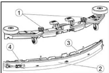
Adjusting the height
The height adjustment affects the bending of the suction lips on contact with the floor.
Note
Standard setting: 3 washers above, 3 washers below the suction bar.
Uneven floor: 5 washers above, 1 washer below the suction bar.
Very smooth floor: 1 washer above, 5 washers below the suction bar.
- Unscrew the nuts.
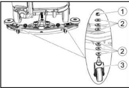
①Nut
② Washer
③ Spacer roller with holder
2. Place the desired number of washers between the suction bar and the spacer roller.
3. Fit the remaining unused washers above the spacer roller.
4. Screw on the nut and tighten.
5. Repeat the entire procedure at the second spacer roller.
Note
Set both spacer rollers to the same height.
Adjusting the squeegee blades
The squeegee blades only need to be adjusted on the D cleaning head.
- Adjust the squeegee blades by turning the setting wheel so that the squeegee blade touches the ground.
- Turn the adjustment wheel an additional 1 rotation down.
Cleaning
- Sit on the seat.
- Insert the Intelligent Key
- Set the safety switch to "1".
- Set the travel direction switch to forward travel.
- Set the program switch to the desired cleaning program.
- Determine the speed with the accelerator pedal.
- Determine the travel direction with the steering wheel.
- Drive over the surface to be cleaned.
Finishing operation
Finishing cleaning
- Set the program switch to drive.
- Continue moving for approximately 10 seconds. The residual water is vacuumed up.
- Turn the program switch to "OFF".
- Remove the Intelligent Key
- Charge the battery if necessary.
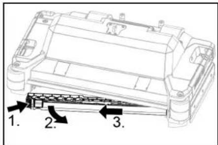
Draining the waste water
△WARNING
Improper disposal of waste water Environmental pollution
Observe the local waste water treatment regulations.
Note
When the waste water tank is full, the suction flow is interrupted by a float to prevent the waste water tank from overflowing. In this case, drain the waste water.
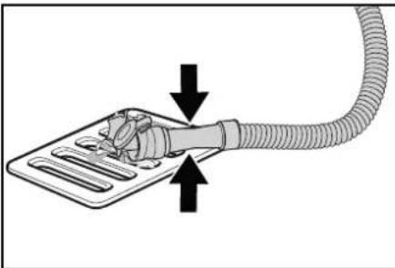
- Remove the waste water drain hose from the support and open the drain hose cover.
natural_image
Diagram showing a hand holding a flexible hose connected to a rectangular device with ventilation slots, indicating fluid or electrical connection (no text or symbols present)- Squeeze the end of the hose and lower it over the disposal facility.
- Adjust the strength of the waste water jet by squeezing the end of the hose.
- Rinse the waste water tank with clear water.
- Close the drain hose cover.
- Press the waste water hose into the support on the device.
Empty the coarse dirt container
- Lift the coarse dirt container and pull it out.
- Empty the coarse dirt container.
- Reinstall the coarse dirt container.
Draining fresh water
- Open the fresh water tank cap.
- Drain the fresh water.
- Clean the filter.
- Fit the fresh water tank cap.
Shutting down the unit
- Turn the key-operated switch to "OFF".
- Remove the Intelligent Key
- Secure the device against rolling away.
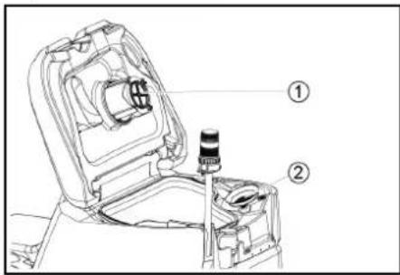
- Open the lid of the waste water tank and secure it with the support so that the waste water tank can dry out. To do this, swing the support down and position the lower end at the desired level when swinging down the cover.
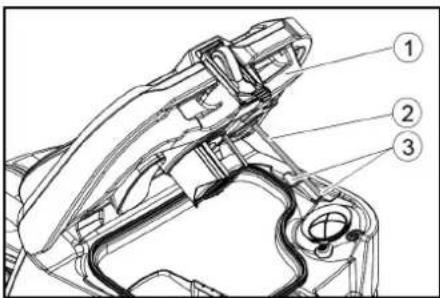
① Waste water tank cap
②Support
③level
- Charge the battery if necessary.
Grey Intelligent Key
The grey Intelligent Key grants the supervisory staff extended authorizations and setting options.
1. Insert the Intelligent Key
2. Select the desired function by turning the info button.
Transport journey
- Set the program selector switch to "TRANSPORT MODE".
- Press the Info button.
The following functions can be executed from the
TRANSPORT MODE menu: - Set maximum speed
• Show operating hours counter - Clearing the maintenance counter
• Show software versions - Adjust the R or D cleaning head
- Setting after-running times
- Setting the language
• Key management
• Activate factory setting
Maximum speed
The maximum speed can be limited in the "max speed" menu.
- Turn the info button until "max speed" is shown on the display.
- Press the Info button.
- Turn the info button until the desired maximum speed is displayed.
- Press the Info button.
Note
The working speed cannot exceed the maximum speed set.
Resetting the maintenance counter
If maintenance work shown in the display has been carried out, the corresponding maintenance counter must then be reset.
- Turn the Info button until "maintenance count." is displayed.
- Press the Info button.
The counter readings are displayed.
-
Turn the info button until the counter to be cleared is highlighted.
-
Press the Info button.
- Select "yes" by turning the Info button.
- Press the Info button. The counter is cleared.
Adjusting the cleaning head
- Turn the Info button until "brush head" is displayed in the menu.
- Press the Info button.
- Turn the info button until the type of the built-in cleaning head is highlighted.
"Roll" = R cleaning head
"Disc" = D cleaning head
- Press the Info button.
After-running time
- Turn the info button until the "delay times" menu item appears on the display.
- Press the Info button.
- Turn the info button until the desired assembly is highlighted.
- Press the Info button.
- Turn the info button until the desired after-running time is displayed.
- Press the Info button.
Setting the language
- Turn the info button until the "language" menu item appears on the display.
- Press the Info button.
- Turn the info button until the desired language is highlighted.
- Press the Info button.
Key management
The menu item "key menu" enables authorizations for yellow Intelligent Keys and the language of the display.
1. Insert the grey Intelligent Key.
2. Turn the info button until the "key menu" menu item appears on the display.
3. Press the Info button.
4. Remove the grey Intelligent Key and insert the yellow Intelligent Key to be personalized.
5. Select the menu item to be changed by turning the info button.
6. Press the Info button.
7. Select the setting of the menu item by turning the info button.
8. Confirm the setting by pressing the menu item.
9. Select the next menu item to be changed by turning the info button.
10. After all settings have been made, call up the "save" menu by turning the info button.
11. Press the Info button.
The authorizations are saved.
Factory setting
The factory settings for all cleaning parameters are restored.
- Turn the info button until the "factory settings" menu item is displayed.
- Press the Info button.
- Turn the Info button until "yes" is highlighted.
- Press the Info button.
Adjusting parameters for cleaning programs
All parameters for cleaning programs are retained until another setting is selected.
- Set the program switch to the desired cleaning program.
- Press the Info button.
The first adjustable parameter is displayed. - Press the Info button The adjusted value flashes
- Set the desired value by turning the Info button.
- Confirm the changed setting by pressing the Info button or wait until the set value is automatically accepted after 10 seconds.
- Select the next parameter by turning the Info button.
- After changing all desired parameters, turn the Info button until the "exit" menu item is displayed.
- Press the Info button.
The menu is exited.
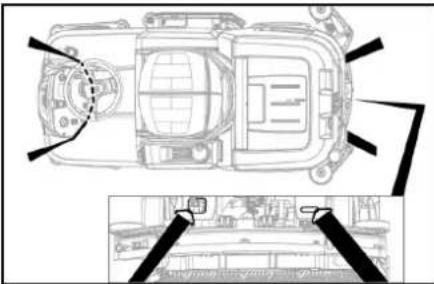
Transport
△DANGER
Driving on slopes
Risk of injury
Observe the maximum permissible gradient when driving the device on slopes for loading and unloading purposes (see chapter "Technical data").
Drive slowly.
△CAUTION
Failure to observe the weight
Risk of injury and damage
Be aware of the weight of the device during transportation.
- With the D cleaning head installed, remove the disc brushes from the brush head.
- When transporting in vehicles, secure the device against slipping and tipping over according to the applicable guidelines.
natural_image
Top-down technical sketch of a car interior with structural details and a close-up inset showing a vehicle exterior (no text or symbols)Storage
△CAUTION
Failure to observe the weight
Risk of injury and damage
Be aware of the weight of the device during storage.
ATTENTION
Frost
Destruction of the device through freezing water
Drain all water from the device.
Store the device in a frost-free location.
• This device may only be stored indoors.
- Fully charge the batteries before storing them for a long period.
- Fully charge the batteries at least every month during storage.
Care and maintenance
△DANGER
Inadvertently starting up device
Risk of injury, electric shock
Turn the program switch to the "OFF" position.
Remove the Intelligent Key prior to all work on the device.
Pull out the charger mains plug.
Unplug the battery connector.
- Drain and dispose of the waste water and fresh water.
Maintenance intervals
Each time after use
ATTENTION
Improper cleaning
Risk of damage.
Do not spray the device with water.
Do not use aggressive cleaning agents.
A detailed description of the individual maintenance
work is provided in the chapter "Maintenance Work".
- Drain the waste water
- Rinse the waste water tank with clear water.
- Clean the coarse dirt filter.
- Only with R cleaning head: Remove the coarse dirt container and empty it.
- Clean the exterior of the device using a damp cloth, wetted with a mild washing lye.
- Check the suction lips, check for wear and replace if necessary.
- Clean the squeegee blades, check for wear and replace if necessary.
- Clean the brushes, check for wear and replace if necessary.
-
Charge the battery.
-
If the charging state of the battery is below 50%, charge the battery fully and without interruption.
- If the charging slate of the battery is above 50%, only recharge the battery if the entire operating duration will be required when next used.
Weekly
- When used regularly, charge the battery fully and without interruption at least once a week.
Monthly
A detailed description of the individual maintenance work is provided in the chapter "Maintenance Work".
- If the device is temporarily shut down: Perform equalization charging of the battery.
- Check battery poles for oxidation, brush off if necessary. Make sure the connection cables are firmly in place.
- Clean the seals between the waste water tank and the cover, check for leaks and replace if necessary.
● Drain the fresh water tank and flush out deposits - Clean the fresh water filter.
- Check the acid density of the cells if the batteries are not maintenance-free.
-
Only with R cleaning head: Clean the brush tunnel.
-
Only with R cleaning head: Clean the water distribution strip on the cleaning head.
- For longer periods of disuse, shut down the device when the battery is fully charged. Fully charge the battery at least once a month.
Annually
● Have the prescribed inspection performed by Customer Service.
Safety inspection/maintenance contract
You can agree on regular safety inspections or close a maintenance contract with your dealer. Please seek advice on this.
Maintenance work
Turn over or replace the worn suction lips
The suction lips must be turned over or replaced when worn out.
The suction lips can be turned 3 times until all 4 edges are worn.
1. Remove the suction bar.
2. Unscrew the star handles.
① Star grip
②Strap
③Inner part of the suction bar
④ Tension lock
- Pull out the inner part of the suction bar.
- Open the tension lock.
- Remove the strap.
- Release the suction lips from the inner part.
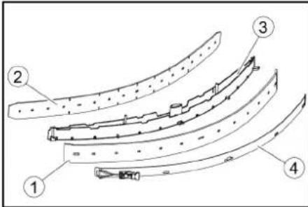
① Squeegee blade
②Support lip
③Inner part of the suction bar
④Strap
- Press the turned or new suction lips onto the knobs of the inner part of the suction bar.
- Attach the strap.
- Push the inner part of the suction bar into the upper part.
- Screw in and tighten the star handles.
Cleaning the coarse dirt filter
- Open the waste water tank cover.
① Coarse dirt filter
②Fluff filter
- Pull the coarse dirt filter upwards and off.
- Rinse off the coarse dirt filter under running water.
- Reinsert the coarse dirt filter into the waste water tank.
Cleaning the float and fluff filter
- Open the waste water tank cover.
①Float
②Fluff filter
2. Rinse the float with clear water.
3. Remove and clean the fluff filter.
Replacing the disc brush
Note
Replace the disc brushes when the bristle length has reached 10 mm.
- Raise the cleaning head.
- Push the brush replacement pedal down.
- Pull the disc brush sideways and out from underneath the cleaning head.
- Hold the new disc brush under the cleaning head, then press upwards and latch it into position.
Replacing the roller brushes
Note
Replace the roller brushes when the bristle length has reached 10 mm.
- Raise the cleaning head.
- Pull out the brush replacement handle.
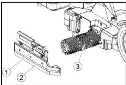
① Brush replacement handle
② Bearing cover with squeegee blade
③ Roller brush
- Remove the bearing cover including the squeegee blade.
- Pull out the roller brush.
- Fit the new roller brush and centre it on the driver.
①Driver
②Mounting mandrel
- Install the bearing cover with the squeegee blade.
Note
Make sure the roller brush sits on the mounting mandrel and not underneath.
- Pivot the brush replacement handle upwards and latch it into place.
- Repeat the entire procedure at the other side.
Cleaning the fresh water filter
- Drain the fresh water (see chapter "Draining fresh water").
- Unscrew the fresh water tank cap.
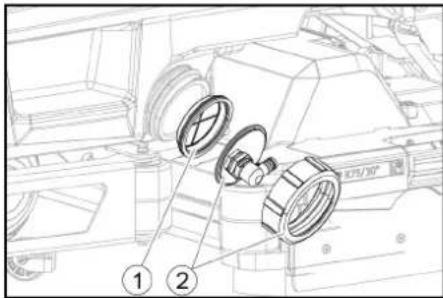
① Fresh water filter
②Fresh water tank lock
- Pull out the fresh water filter and rinse with clean water.
- Insert the fresh water filter.
- Fit the fresh water tank lock. Note: Take care to ensure that the hose connection in the fresh water tank cap is positioned at the lowest point in the tank after screwing the cap in place.
Cleaning the water distribution strip
- Press the latch in the direction of the arrow and hold it there.
- Pivot the water distribution strip forward.
- Pull out the water distribution strip lengthways.
- Clean the water distribution strip.
- Fit the water distribution strip back into the cleaning head and snap the lock into place.
Cleaning batteries
- Wear safety goggles, protective clothing and protective gloves.
- Keep the battery cell plugs closed.
- Remove the batteries.
- Only clean the plastic parts of the batteries and the battery compartment with water or water-soaked cleaning cloths without additives.
- Dry the surfaces after cleaning.
- Reinstall the batteries.
Resetting the maintenance counter
If maintenance work shown in the display has been carried out, the corresponding maintenance counter must then be reset.
Note
Resetting the maintenance counters is described in the chapter "Grey Intelligent Key".
Troubleshooting guide
△DANGER
The device can start unintentionally
People working on the device can be injured.
Remove the Intelligent Key prior to all work on the device.
Before carrying out any work, pull the mains plug of the internal charger out of the socket.
Disconnect the battery connector before performing any work.
- Drain the waste water.
- Drain the remaining fresh water.
Note
If the malfunction cannot be remedied with the following instructions, contact Customer Service.
Malfunctions with information shown on the display
If the displayed malfunction is not in the following list, do the following:
- Turn the key-operated switch to "OFF".
- Wait 10 seconds.
- Set the program switch to the previous function.
- If the malfunction recurs, call Customer Service.
| Malfunction Rectification | |
| fresh water empty 1. Refill the fresh water tank | |
| water valve blocked 1. Set the program | me switch to "OFF".2. Wait 10 seconds.3. Set the program switch to the desired program. |
| overload brush head 1. Reduce the contact pressure of the brushes. | |
| blocked main brush | 1. Check if the brushes are blocked by a foreign body and remove the foreign body if necessary.2. Set the programme switch to "OFF".3. Wait 10 seconds.4. Set the program switch to the desired program. |
| overload side brush 1. Reduce the contact pressure of the side scrubbing deck brush. | |
| blocked drive motor 1. Check the wheels for blockage, remove foreign objects.2. Set the programme switch to "OFF".3. If the engine has overheated, let it cool down for at least 15 minutes, otherwise wait 10 seconds.4. Set the program switch to the desired program. | |
| battery low 1. Set the program selector switch to TRANSPORT MODE.2. Drive the device directly to the charger (or with an internal charger to the socket). Avoid gradients.3. Charge the battery. | |
| battery empty 1. Set the program selector switch to TRANSPORT MODE.2. Drive the device by the shortest route to the charger (or to the socket in the case of an internal charger). Avoid gradients.3. Charge the battery. | |
| seat switch open | 1. Relieve the driver's seat briefly so that the control can check the function of the seat contact switch. |
| switch on! | 1. Set the safety switch to "1". |
| restart machine | 1. Set the programme switch to "OFF".2. Wait 10 seconds.3. Set the program switch to the desired program. |
| release throttle | 1. Release the accelerator pedal. |
Malfunctions without information shown on the display
| Malfunction Rectification | |
| The device cannot be started 1. Sit in the driver's seat.2. Take your foot off the accelerator before switching on the safety switch.3. Turn the safety switch to "1".4. Check the battery and charge if necessary.5. Set the programme switch to "OFF".6. Wait 10 seconds.7. Set the program switch to the desired program.8. If possible, only drive the device on level ground.9. Check the parking brake if necessary.If the fault still occurs, call Customer Service. | |
| The device is no longer running, display shows "battery empty" | 1. Set the programme switch to "OFF".2. Wait 10 seconds.3. Set the program selector switch to "TRANSPORT MODE".4. Drive to the charging station.5. If the device still does not run, charge the battery on site or unlock the brake (see "Operation/pushing the device") and push the device to the charging station. |
| The device moves unevenly (jerks) when starting and stopping. | 1. Unlock the brake lock (see "Operation/pushing the device"). |
| The water volume is insufficient | 1. Check the fresh water filling level, if necessary fill the tank completely so that the air is pressed out.2. Remove and clean the fresh water filter.3. Insert the filter and screw on the cap.4. Check the hoses for clogging and clean if necessary. |
| The fresh water display shows the wrong filling level after emptying the tank manually. | 1. Use the device. During operation, the hose system will vent and the filling level display will correct itself. |
| The bar of the filling level display is flashing, "fresh water empty" display | 1. Refill the fresh water tank. |
| The suction performance is too low | 1. Clean the seals between the waste water tank and the cover, check for leaks and replace if necessary.2. Check the fluff filter for soiling and clean if necessary.3. Clean the suction lips at the suction bar, turn over or replace if necessary.4. Close the lid on the waste water drain hose.5. Close the cover of the waste water tank rinsing system.6. Check the suction hose for clogging and clean if necessary.7. Check the suction hose for leaks and replace if necessary.8. Check the adjustment of the suction bar. |
| The cleaning results are unsatisfactory | 1. Set the appropriate cleaning program for the cleaning task.2. Use suitable brushes for the cleaning task.3. Use a suitable detergent for the cleaning task.4. Reduce the driving speed.5. Adjust the contact pressure.6. Adjust the squeegee blades.7. Check the brushes for wear and replace if necessary.8. Check the water output. |
| The brushes do not rotate 1. Reduce the contact pressure.2. Check if the brushes are blocked by a foreign body and remove the foreign body if necessary.3. If the motor is overloaded, let the motor cool down.4. Set the programme switch to "OFF".5. Wait 10 seconds.6. Set the program switch to the desired program.7. Check that the plug of the device is plugged into the cleaning head. | |
| The device does not brake | 1. Undo the brake lock (see "Operation / Pushing the device"). |
| The waste water drain hose is clogged | 1. Open the dosing unit cover at the drain hose.2. Pull the suction hose off the suction bar and close it by hand.3. Set the programme switch to "Vacuum".The blockage is sucked out of the drain hose into the waste water tank. |
Warranty
The warranty conditions issued by our sales company responsible apply in all countries. We shall remedy pos-
sible malfunctions on your device within the warranty period free of cost, provided that a material or manufacturing defect is the cause. In a warranty case, please
contact your dealer (with the purchase receipt) or the next authorised customer service site. (See overleaf for the address)
Accessories
Cleaning head with roller brush accessories
A: Packaging unit, B: Quantity required by the device
| Description R 75 | Part no. | Description A B | ||
| Roller brush, red (medium, standard) | 4.035-605.0 | For maintenance cleaning of heavily soiled floors. | 1 | 2 |
| Roller brush, white (soft) | 6.907-771.0 | For polishing and maintenance cleaning of sensitive floors. | 1 | 2 |
| Roller brush, orange (high / low) | 6.907-730.0 | For scrubbing structural floors (safety tiles, etc.). | 1 | 2 |
| Roller brush, green (hard) | 6.907-731.0 | For basic cleaning of heavily soiled floors and for coating removal (e.g. waxes, acrylates). | 1 | 2 |
| Roller brush, black (very hard) | 6.907-732.0 | 1 | 2 | |
| Microfiber roller | 4.114-007.0 | For maintenance cleaning of smooth floors. | 1 | 2 |
| Pad roller shaft | 4.762-627.0 | For holding roller pads. | 1 | 2 |
| Roller pad, yellow (soft) | 6.369-454.0 | For polishing floors | 20 | 96; 106 |
| Roller pad, red (medium) | 6.369-456.0 | For cleaning lightly soiled floors. | 20 | 96; 106 |
| Roller pad, green (hard) | 6.369-455.0 | For cleaning normal to heavily soiled floors. | 20 | 96; 106 |
Cleaning head with disc brushes accessories
A: Packaging unit, B: Quantity required by the device
| Description | D 75 Part no. | Description | A | B |
| Disc brush, natural colour (soft) | 4.905-020.0 | For polishing floors. | 1 | 2 |
| Disc brush, white | 4.905-019.0 | For polishing and maintenance cleaning of sensitive floors. | 1 | 2 |
| Description D 75 | Part no. | Description | A | B |
| Disc brush, red (medium, standard) | 4.905-018.0 | For cleaning lightly soiled or sensitive floors. | 1 | 2 |
| Disc brush, black (hard) 4.905-021.0 For cleaning heavily soiled | floors. 1 2 | |||
| Fine diamond pad, green 6.371-236.0 For refreshing lime-containing coverings and epoxy resin-coated floors. 5 2 | ||||
| Coarse diamond pad, white 6.371-252.0 5 | 2 | |||
| Medium diamond pad, yellow 6.371-253.0 5 | 2 | |||
| Pad drive board 4.762-447.0 For holding pads. 1 2 | ||||
Suction bar accessories
A: Packaging unit, B: Quantity required by the device
| Description | Part no. | Description | A | B |
| Suction lip set, front PU (red), rear Linatex | 4.039-366.0 | Standard | Pair | 1 pair |
| Suction lip set, Linatex | 4.039-356.0 | Tear-proof | Pair | 1 pair |
| PU suction lip set | 4.039-357.0 | Oil-proof | Pair | 1 pair |
Technical data
| B 110 Classic D 75 | B 110 Classic R 75 | |||
| General | ||||
| Driving / cleaning speed | km/h | 6 | 6 | |
| Transport speed km/h | 6 | 6 | ||
| Travel speed, backwards | km/h | 4 | 4 | |
| Theoretical surface performance | m^2/h | 4500 | 4500 | |
| Practical surface performance | m^2/h | 3150 | 3150 | |
| Fresh water tank capacity | I 130 | 130 | ||
| Waste water tank capacity | I | 110 | 110 | |
| Coarse dirt container capacity | I - | 1.8 | ||
| Water dosage | l/min | 0...8 | 0...8 | |
| Load per unit area (with driver and full fresh water tank) | ||||
| Surface pressure | N/mm2 | 0.64 | 0.64 | |
| Load per unit area (weight / parking area) | kg/m2 | 563 | 563 | |
| Dimensions | ||||
| Length | mm | 1660 | 1660 | |
| Width | mm | 1035 | 1035 | |
| Wide suction bar | mm | 1000 | 1000 | |
| Height | mm | 1480 | 1480 | |
| Working width | mm | 750 | 750 | |
| Packaging dimensions lxwxh | mm | 1715x1140x1625 | 1715x1140x1625 | |
| Turning circle | mm | 1750 | 1750 | |
| Battery compartment dimensions lxwxh | mm | 420x630x400 | 420x630x400 | |
| Tyres | ||||
| Front wheel, width | mm | 90 | 90 | |
| Front wheel, diameter | mm | 250 | 250 | |
| Rear wheel, width | mm | 75 | 75 | |
| Rear wheel, diameter | mm | 290 | 290 | |
| Weight | ||||
| Approved total weight | kg | 720 | 720 | |
| Net weight (transport weight) | kg | 380 | 380 | |
| Typical operating weight | kg | 590 | 590 | |
| Brush contact force, max. | N (kg) | 736 (75) | 736 (75) | |
| Brush contact pressure, max. | N / m^2(g/cm^2) | 510 (500) 510 (500) | ||
| Device performance data | ||||
| Nominal voltage | V | 24 | 24 | |
| Battery capacity* (Factory installed, if Bp Pack version) | Ah (5 h) | 170 | 170 | |
| Mean power input | W | 2350 | 2350 | |
| Nominal power | W | 2500 | 2500 | |
| Driving motor power | W | 600 | 600 | |
| Suction turbine power | W | 600 | 600 | |
| Brush drive power | W | 2 x 600 | 2 x 600 | |
| Degree of protection | IPX3 | IPX3 | ||
| Vacuuming | ||||
| Suction performance, air quantity | l/s | ~25 | ~25 | |
| Vacuum (max.) | kPa (mbar) | ~17 (~170) | ~17 (~170) | |
| Vacuum (in operation) | kPa (mbar) | ~5 (~50) | ~5 (~50) | |
| Cleaning brushes | ||||
| Brush diameter | mm | 410 | 100 | |
| Brush length | mm | - | 705 | |
| Brush speed | 1/min | 180 | 1200 | |
| External charger | ||||
| Nominal voltage | V | 230 | 230 | |
| Frequency | Hz | 50-60 | 50-60 | |
Charging current A 50 50
Weight kg 4.5 4.5
Ambient conditions
Permissible temperature range °C 5...40 5...40
Water temperature max. °C 50 50
| Relative humidity | % | 20...90 | 20...90 |
| Incline | |||
| Max. working area slope | % | 10 10 | |
| Short distance incline (max. 10 m) transport, loading | % | 22 22 | |
| Determined values in acc. with EN 60335-2-72 | |||
| Hand-arm vibration value | m/s^2 | <2.5 | <2.5 |
| Seat vibration value | m/s^2 | <2.5 | <2.5 |
| Uncertainty K | dB(A) | 0.2 0.2 | |
| Sound level L_pA eco operation | dB(A) | 59.2 | 59.2 |
| Sound level L_pA normal operation | dB(A) | 63.6 | 63.6 |
| Uncertainty K_pA | dB(A) | 1.6 1.6 | |
| Sound power level L_WA + Uncertainty K_WA eco operation | dB(A) | 74.1 | 74.1 |
| Sound power level L_WA + Uncertainty K_WA normal operation | dB(A) | 78.7 | 78.7 |
Subject to technical modifications.
Declaration of Conformity
EU Declaration of Conformity
We hereby declare that the machine described below complies with the relevant basic safety and health requirements in the EU Directives, both in its basic design and construction as well as in the version placed in circulation by us. This declaration is invalidated by any changes made to the machine that are not approved by us.
Product: Floor cleaner
Type: 1.161-xxx
Currently applicable EU Directives
2006/42/EC (+2009/127/EC)
2014/30/EU
2014/53/EU (TCU)
National standards used
The signatories act on behalf of and with the authority of the company management.

Chairman of the Board of Management

Director Regulatory Affairs & Certification
Documentation supervisor:
S. Reiser
Alfred Kärcher SE & Co. KG
Alfred-Kärcher-Str. 28 - 40
71364 Winnenden (Germany)
Ph.: +49 7195 14-0
Fax: +49 7195 14-2212
Winnenden, /09/01
Declaration of Conformity (UK)
We hereby declare that the product described below complies with the relevant provisions of the following UK Regulations, both in its basic design and construction as well as in the version put into circulation by us. This declaration shall cease to be valid if the product is modified without our prior approval.
Product: Floor cleaner
Type: 1.161-xxx
Currently applicable UK Regulations
S.I. 2008/1597 (as amended)
S.I. 2016/1091 (as amended)
S.I. 2017/1206 (as amended) (TCU)
National standards used
The signatories act on behalf of and with the authority of the company management.
H. Jenner
Chairman of the Board of Management
S. Reiser
Director Regulatory Affairs & Certification
Documentation supervisor:
S. Reiser
Alfred Kärcher SE & Co. KG
Alfred-Kärcher-Str. 28 - 40
71364 Winnenden (Germany)
Ph.: +49 7195 14-0
Fax: +49 7195 14-2212
Winnenden, /09/01
Contenu
① Klaxon
①Bande de serrage
②Planche
③Cale
4 Bois
natural_image
Technical line drawing of a mechanical lift or platform with no visible text or symbols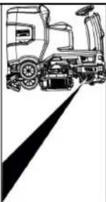
natural_image
Line drawing of a truck with wheels and a sensor, casting a shadow on the side (no text or symbols)natural_image
Technical line drawing of a mechanical assembly with pulleys and wheels (no text or symbols)① Vis
②Ecrou
③ Niveau à bulle
①Ecrou
②Rondelle
natural_image
Diagram of a medical device with a coiled tube and directional arrows indicating movement or force (no text or symbols)Stockage
△PRÉCAUTION
2006/42/CE (+2009/127/CE)
2014/30/UE
2014/53/EU (TCU)

H. Jenner
Chairman of the Board of Management

S. Reiser
Director Regulatory Affairs & Certification
71364 Winnenden (Germany)
1 Clacson
natural_image
Technical line drawing of a forklift on a platform with metal rails (no text or symbols)
natural_image
Side view line drawing of a truck with wheels and a sensor, no text or symbols present①Leva di sblocco
natural_image
Technical line drawing of a mechanical assembly with pulleys and gears (no text or symbols)①Dado
②Rondella
natural_image
Diagram showing a hand connecting a flexible hose to a device with directional arrows indicating movement (no text or symbols)Stoccaggio
⚠PRUDENZA
Mancata osservanza del peso
①Filtro per sporco grossolano
②Filtro pelucchi
①Galleggiante
②Filtro pelucchi

H. Jenner
Chairman of the Board of Management
S. Reiser
Director Regulatory Affairs & Certification
71364 Winnenden (Germany)
Tel.: +49 7195 14-0
Fax: +49 7195 14-2212
Winnenden, 01/09/
①Bocina
natural_image
Technical line drawing of a mechanical lift or platform with no visible text or symbols
natural_image
Line drawing of a mechanical vehicle with a spotlight beam (no text or symbols)natural_image
Technical line drawing of a mechanical assembly with pulleys and gears (no text or symbols)①Tornillo
②Tuerca
③Nivel del agua
①Tuerca
② Arandela
natural_image
Diagram showing a hand holding a device with a coiled cable, indicating force or movement (no text or symbols present)natural_image
Top-down line drawing of a car interior with dashboard and steering wheel, plus an inset photo of a vehicle exterior (no text or symbols)Almacenamiento
△PRECAUCIÓN
①Flotador
②Filtro de pelusas
2006/42/CE (+2009/127/CE)
2014/30/UE
2014/53/UE (TCU)

H. Jenner
Chairman of the Board of Management

S. Reiser
Director Regulatory Affairs & Certification
71364 Winnenden (Germany)
Tel.: +49 7195 14-0
Fax: +49 7195 14-2212
Winnenden, 01/09/
Índice
①Buzina
②Interruptor do sentido de marcha
③Interruptor de programa
④ Chave inteligente
⑤ Visor
⑥Botão Info
①Braçadeira
②Tábua
③Calço
④ Viga-calço
natural_image
Technical line drawing of a mechanical or industrial robotic platform with no visible text or symbolsnatural_image
Technical line drawing of a mechanical assembly with pulleys and wheels (no text or symbols)①Porca
②Anilha
③Rolo distanciador com suporte
natural_image
Diagram of a flexible hose connecting a plastic tray with a coiled hose, showing directional arrows (no text or symbols)natural_image
Top-down schematic of a car showing front and rear views with no text or symbolsArmazenamento
△CUIDADO
2006/42/CE (+2009/127/CE)
2014/30/UE
2014/53/UE (TCU)

H. Jenner
Chairman of the Board of Management
S. Reiser
Director Regulatory Affairs & Certification
① Claxon
①Spanband
②Bord
③Blok
④Kanthout
natural_image
Technical line drawing of a mechanical lift or platform with no visible text or symbols① Zuigslang
②Zuigbalkophanging
③Zuigbalk
④Klemhendel
①Ontgrendelhendel
natural_image
Technical line drawing of a mechanical assembly with pulleys and gears (no text or symbols)1 Schroef
② Moer
③Waterweegschaal
① Moer
②Onderlegring
natural_image
Diagram of a medical device with a coiled tube and directional arrows indicating movement or force (no text or symbols)①Deksel vuilwatertank
② Steun
③ Niveau
- Eventueel de accu laden.
Opslag
⚠VOORZICHTIG
①Greep borstelwissel
①Filter verswater
②Afsluiting verswaterreservoir

H. Jenner
Chairman of the Board of Management

S. Reiser
Director Regulatory Affairs & Certification
71364 Winnenden (Germany)
Tel.: +49 7195 14-0
Fax: +49 7195 14-2212
İçindekiler
Genel uyarılar 72
Fonksiyon.... 72
①Korna
①Gergi bandı
②Tahta
③Takoz
④ Kenar kereste
natural_image
Technical line drawing of a mechanical cleaning or inspection machine with no visible text or symbols①Vakum hortumu
natural_image
Line drawing of a truck with a roof and side-mounted equipment, no text or symbols present①Kilit açma kolu
natural_image
Technical line drawing of a mechanical assembly with pulleys and gears (no text or symbols)①Civata
② Somun
③ Su terazisi
①Somun
②Pul
③Tutuculu ara silindir
natural_image
Diagram showing a hand connecting a plastic component with a coiled hose, indicating fluid or mechanical assembly (no text or symbols present)natural_image
Top-down schematic of a car interior with labeled components and an inset photo showing dashboard and engine (no text or symbols present)Depolama
TEDBIR

Şamandıra

oz süzgeci
①Temiz su filtresi
2006/42/AT (+2009/127/AT)
2014/30/AB
2014/53/EU (TCU)

H. Jenner
Chairman of the Board of Management

S. Reiser
Director Regulatory Affairs & Certification
mation blir heta under drift.
①Horn
①Spännband
②Bräda
③Kloss
④Träbalk
natural_image
Line drawing of a cleaning or inspection machine on a platform (no text or symbols)① Sugslang
② Sugbalksfäste
③Sugbalk
④Klämspak
① Batterikontakt, enhetssida
② Batterikontakt, batterisida
①Frigöringsspak
natural_image
Technical line drawing of a mechanical assembly with pulleys and gears (no text or symbols)①Skruv
②Mutter
③Vattenpass
natural_image
Diagram of a hand holding a flexible hose with directional arrows indicating movement or force (no text or symbols)natural_image
Top-down schematic of a car interior with labeled components and an inset photo showing a vehicle exterior (no text or symbols present)Förvaring
⚠FÖRSIKTIGHET
1 Grovsmutssil
②Luddsil

H. Jenner
Chairman of the Board of Management

S. Reiser
Director Regulatory Affairs & Certification
D-71364 Winnenden (Germany)
Tfn: +49 7195 14-0
Fax: +49 7195 14-2212
Winnenden, 01.09.
Sisältö
Yleisiä ohjeita 92
Toiminta.... 92
① Äänimerkki
②Ajosuuntakytkin
③ Ohjelmakytkin
④ Intelligent Key
⑤ Näyttö
⑥Tietopainike
⑦ Turvakytkin
①Kiinnityshihna
②Lauta
③Palkki
④Tukipuu
natural_image
Technical line drawing of a mechanical cleaning or inspection machine on a platform (no text or symbols visible)①muletku
②mupalkin ripustus
③mupalkki
④ Kiristysvipu
①Vapautusvipu
natural_image
Technical line drawing of a mechanical assembly with pulleys and gears (no text or symbols)① Ruuvi
②Mutteri
③ Vesivaaka
①Mutteri
② Aluslaatta
natural_image
Diagram showing a hand holding a flexible hose with arrows indicating force or movement (no text or symbols)natural_image
Top-down technical diagram of a car interior with structural components and dashboard (no text or labels)Varastointi
△VARO
①Karkean lian seula
② Nukkasihti

H. Jenner
Chairman of the Board of Management
S. Reiser
Director Regulatory Affairs & Certification
71364 Winnenden (Germany)
Puh.: +49 7195 14-0
① Horn
① Strips
②brett
③Blokk
④Firkantlist
natural_image
Technical line drawing of a mechanical or industrial robotic platform with no visible text or symbols① Sugeslange
② Sug bjelkeoppheng
③Sugebom
④Låsearm
2. Sett sugebommen inn i sugebomopphenget.
3. Skyv begge forriglingene nedover.
Batterier
① Batteriplugg, maskinside
①Lås opp spaken
natural_image
Technical line drawing of a mechanical assembly with pulleys and gears (no text or symbols)① Skrue
②Mutter
③Water
①Mutter
②Underlagsskive
③Avstandshjul med holder
2. Plasser ønsket antall skiver mellom sugebommen og avstandsrullen.
3. Plasser resten av underlagsskivene oppå avstandshiulet.
4. Skru på mutrene og trekk den til.
5. Gjenta fremgangsmåten på det andre avstandshju-
let.
Merknad
natural_image
Diagram showing a hand inserting a plug into a device with a coiled tube, indicating fluid or electrical connection (no text or symbols present)①Deksel bruktvannstank
②Støtte
③Trinn
5. Lad eventuelt batteriet.
natural_image
Top-down technical diagram of a car interior with structural components and dashboard (no text or labels)Lagring
△FORSIKTIG
① Stjernehändtak
②Strammebånd
③Innvendig del sugebom
④ Strammelås
3. Trekk ut den innvendige delen av sugebommen.
4. Åpne strammelåsen.
5. Ta av strammebåndet.
6. Løsne sugebladene fra den innvendige delen.
①Avstrykerblad
②Støtteblad
③Innvendig del sugebom
④Strammebänd
- Trykk de vendte eller nye sugebladene på knottene på den innvendige delen av sugebommen.
- Monter strammebändet.
- Skyv den innvendige delen av sugebommen inn i overdelen.
- Skru inn stjernegrepene og stram dem.
Rengjøre grovsmussilen
① Grovsmussil
②Losil
①Håndtak for børsteskift
② Lagerdeksel med avstrykerblad
③Børstevalse
①Filter rent vann
②Lokk rentvannstank
- Ta ut filteret for rent vann og spyl det med rent vann.
-
Sett inn filteret for rent vann.
-
Skru på lokket til rentvannstanken. Merk: Påse at slangetilkoblingen i lokket til rent- vannstanken ligger på det dypeste punktet när det er skrudd fast.
2006/42/EF (+2009/127/EF)
2014/30/EU
2014/53/EU (TCU)

Chairman of the Board of Management
S. Reiser
Director Regulatory Affairs & Certification
71364 Winnenden (Germany)
Tlf.: +49 7195 14-0
① Horn
①Spændebänd
②Bræt
③Klods
④Firkanttømmer
natural_image
Technical line drawing of a mechanical or industrial robotic platform with no visible text or symbols① Sugeslange
②Sugebjælkeophaeng
③Sugebjælke
④Klemhändtag
① Batteristik, maskinside
②Batteristik, batteriside
Faresituation under driften
①Sikkerhedshåndtag
natural_image
Technical line drawing of a mechanical assembly with pulleys and gears (no text or symbols)① Skrue
②Møtrik
③Vaterpas
①Møtrik
②Underlagsskive
natural_image
Diagram showing a hand holding a flexible hose connected to a device panel, with arrows indicating direction of movement (no text or symbols present)Opbevaring
△FORSIGTIG
① Stjernegreb
②Spændebånd
① Afstrygningsliste
② Støttelæbe
① Grovsi
②Trævlesi
① Svømmer
②Trevlefilter
①Filter rentvandstank
2006/42/EF (+2009/127/EF)
2014/30/EU
2014/53/EU (TCU)
H. Jenner
Chairman of the Board of Management
S. Reiser
Director Regulatory Affairs & Certification
71364 Winnenden (Germany)
Tlf.: +49 7195 14-0
Fax: +49 7195 14-2212
Winnenden, /09/01
Sisukord
Üldised juhised.... 122
Funktsioon 122
①Signaal
② Sõidusuuna lüliti
③Programmilüliti
④ Nutikas võti
⑤*Ekraan
⑥Info nupp
⑦ Ohutuslüliti
①Pingutuslint
②Laud
③Klots
④Puitpruss
natural_image
Technical line drawing of a mechanical or industrial robotic platform with no visible text or symbolsImitala monteerimine
①mivoolik
②mitala ripphoidik
③Imitala
④ Lukustushoob
-
Pange imitala ripphoidikusse.
-
Pöörake mölemad lukustushoovad alla.
Akud
①Aku pistik, seadme pool
①Vabastushoob
natural_image
Technical line drawing of a mechanical assembly with pulleys and gears (no text or symbols)①Polt
②Mutter
③ Vesilood
①Mutter
②Alusseib
natural_image
Diagram showing a hand connecting a flexible hose to a device with directional arrows indicating movement (no text or symbols)①Mustaveepaagi kaas
②Tugi
③Aste
natural_image
Top-down technical sketch of a car interior with structural components and dashboard (no text or labels)Ladustamine
△ETTEVAATUS
Kaalu eiramine
①Ujuk
② Ebemefilter
①Puhtaveefilter
②Puhtaveepaagi sulgur
2006/42/EÜ (+2009/127/EÜ)
2014/30/EL
2014/53/EL (TCU)
H. Jenner
Chairman of the Board of Management
S. Reiser
Director Regulatory Affairs & Certification
71364 Winnenden (Germany)
Tel: +49 7195 14-0
①Taure
①Spriegotājsiksna
②Dēlis
③ Klucis
4 Brusa
natural_image
Technical line drawing of a mechanical cleaning or inspection machine with no visible text or symbols①Atblokëšanas svira
natural_image
Technical line drawing of a mechanical assembly with pulleys and gears (no text or symbols)①Uzgrieznis
②Paplāksne
natural_image
Diagram showing a hand connecting a flexible hose to a rectangular device with internal components, indicating fluid or electrical connection (no text or symbols present)natural_image
Top-down schematic of a car's front and rear views, showing structural components and engine compartment (no text or labels)Uzglabāšana
⚠UZMANĪBU
Svara neievērošana
①Pludinš
②Pūku siets
- Noskalojiet pludinu ar tīruūdeni.
- Iznemiet un notīriet pūku filtru.
Disku sukas nomaina
Norādījum
① Svaigā ùdens filtrs
Chairman of the Board of Management
S. Reiser
Director Regulatory Affairs & Certification
① Garso signalas
①Suveržimo juosta ②Lenta
③Trinkelé
④ Medinis tašas
natural_image
Technical line drawing of a mechanical or industrial robotic platform with no visible text or symbols① Siurbimo žarna
① Atblokavimo svirtis
natural_image
Technical line drawing of a mechanical assembly with pulleys and wheels (no text or symbols)①Veržlé
②Poveržlé
③ Tarpo reguliavimo ritinélis su laikikliu
natural_image
Diagram showing a hand connecting a flexible hose to a device with directional arrows indicating movement (no text or symbols)① Nešvaraus vandens bako dangtis
②Atrama
③ Režimas
- Prireikus ikraukite baterija.
natural_image
Top-down line drawing of a car interior with structural components and a close-up inset showing dashboard and engine (no text or symbols)Sandèliavimas
ATSARGIAI
①Šepečio keitimo rankena
②Guolio dangtis su valymo grandikliu
③ Šepetinis velenas
① Švaraus vandens filtras
② Švaraus vandens bako dangtelis
H. Jenner
Chairman of the Board of Management
S. Reiser
Director Regulatory Affairs & Certification
① Klakson
① Opaska zaciskowa
②Deska
③Klocek
④Krawędziak
natural_image
Technical line drawing of a mechanical cleaning or inspection machine with no visible text or symbols① Wąż ssący
natural_image
Technical line drawing of a mechanical assembly with pulleys and wheels (no text or symbols)①Śruba
②Nakrętka
③Poziom wody
①Nakrętka
②Podkładka
natural_image
Diagram of a hand holding a flexible hose with a device, showing mechanical components and directional arrows (no text or symbols)Przechowywanie
△OSTROŻNIE
①Uchwyt gwiażdzisty
②Pasek
①Listwa zgarniacza
①Podest
②Filtr klaczków
①Filtr czystej wody
2006/42/WE (+2009/127/WE)
2014/30/UE
2014/53/EU (TCU)

H. Jenner
Chairman of the Board of Management
S. Reiser
Director Regulatory Affairs & Certification
71364 Winnenden (Germany)
Tel.: +49 7195 14-0
①Rögzítőszalag
②Deszka
③Fakocka
④Élléc
natural_image
Technical line drawing of a mechanical cleaning or inspection machine on a flatbed platform (no text or symbols visible)natural_image
Technical line drawing of a mechanical assembly with pulleys and wheels (no text or symbols)①Csavar
② Anya
③ Vízmérték
① Anya
② Alátét
natural_image
Diagram showing a hand holding a flexible hose connected to a device panel, with arrows indicating direction of movement (no text or symbols present)natural_image
Top-down technical diagram of a car interior with structural components and a close-up view of the dashboard (no text or labels)Tárolás
△VIGYÁZAT
①Durva szennyszürő
②Bolyhszürő
①Úszó
②Bolyhszürö
①Frissvíz-szűrő
O
H. Jenner
Chairman of the Board of Management
S. Reiser
Director Regulatory Affairs & Certification
① Klakson
①Popruh
②Deska
③Blok
④ Dřevěný hranol
natural_image
Technical line drawing of a forklift on a platform with metal racks (no text or symbols)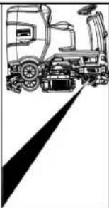
natural_image
Side view of a truck with a roof and side-mounted equipment, no visible text or symbols①Odblokovací páka
natural_image
Technical line drawing of a mechanical assembly with pulleys and wheels (no text or symbols)① Šroub
② Matice
③ Hladina vody
①Matice
②Podložka
natural_image
Diagram of a hand holding a flexible hose with directional arrows indicating movement or force (no text or symbols)natural_image
Top-down schematic of a car interior with labeled components and zoomed-in detail (no text or symbols)Skladování
⚠UPOZORNĚNÍ
① Síto na hrubé nečistoty
② Sítko na vlákna
①Plovák
②Filtr na vlákna
①Filtr čerstvé vody
2006/42/ES (+2009/127/ES)
2014/30/EU
2014/53/EU (TCU)
H. Jenner
Chairman of the Board of Management
S. Reiser
Director Regulatory Affairs & Certification
① Uzáver nádrže na čistú vodu s filtrom na čistú vodu
② Filter na hrubé nečistoty
③Uzáver nádrže na odpadovú vodu
④ Ovládací panel
⑤ Koliesko na nastavenie listu sacej lišty (iba čistiaca hlavica D)
⑥Pedál na výmenu kefy
⑦Volant
⑧ Bočné plášte
⑨ Batéria
⑩Typový štítok
⑪Páka nastavenia sedadla
⑫ Úložný priestor pre čistiacu súpravu „Homebase Box“
⑬* Výstražné svetlo
14 Sedadlo
⑮Západka nádrže na odpadovú vodu
⑯ Plniaci otvor nádrže na čistů vodu
⑰Držiak hadice
⑱Denné svietenie
19 Plynový pedál
20 Plavák
21 Filter na vlákna
⑳ Vypúštacia hadica nádrže na odpadovú vodu
23 Nádrž na odpadovú vodu
24* Držiak mopu
25 Sacia hadica
26 Upínacia páka sacej lišty
27 Uzáver nádrže na odpadovú vodu
28 Sacia lista
29 Čistiaca hlavica
30 Indikátor stavu naplnenia čerstvej vody
31 Nádrž na čistú vodu
* voliteiné
Farebné označenie
① Klaksón
②Prepínač smeru jazdy
③Prepínač programov
④ Inteligentný klúč
⑤ Displej
⑥Tlačidlo Info
①Upínací pás
②Doska
③Brvno
④Drevený hranol
natural_image
Technical line drawing of a mechanical or industrial robotic platform with no visible text or symbols① Nasávacia hadica
②Upevnenie sacej lišty
③ Sacia lišta
④Upínacia páka
2. Saciu listu vložte do upevnenia sacej lišty.
3. Otočte obe upínacie páky smerom nadol.
Batérie
① Zástrčka batérie, strana zariadenia
② Zástrčka batérie, strana batérie
3. Pripojte konektor batérie na strane batérie k nabíjačke.
4. Zapojte elektrickú zástrčku nabíjačky do zásuvky.
5. Proces nabíjania vykonajte podľa návodu na obslu-
hu nabíjačky.
6. Pripojte konektor batérie na strane zariadenia ku konektoru batérie na strane batérie.
7. Nakloňte nádrž na odpadovú vodu smerom dopredu a potom ju zatvorte.
Batérie nenáročné na údržbu (mokré batérie)
ΔNEBEZPEČENSTVO
①Páka na odblokovanie
- Na oboch koncoch páky zasuňte mincu medzi kryt a páku.
- Uvol'nite páku na odblokovanie.
- Presuňte zariadenie.
- Ihned' po procese presúvania opät' odstráňte obe mince.
Nastavenie sedadla
Nastavenie polohy
- Stlačte páku nastavenia sedadla a sedadlo posuňte do požadovanej polohy.
- Uvolnite páku nastavenia sedadla a zaaretujte sedadlo.
Zapnutie prístroja
- Sadnite si na sedadlo vodiča.
- Zasuňte inteligentný klúč.
- Bezpečnostný spínač prepnite do polohy „1“
- Otočte programový spínač na požadovanú funkciu.
- Ak sa na displeji zobrazí niektoré z nižšie uvedených zobrazení, zložte nohu z plynového pedála, prepnite bezpečnostný spínač do polohy „0“ a vykonajte potrebnú údržbovú prácu.
| Displej Činnost' | |
| maintenance squeegee | Vyčistite saciu lištu. |
| maintenance brush head | Skontrolujte opotrebovanie kief a vyčistite ich. |
| maintenance squeegee blade | Skontrolujte opotrebovanie a na-stavenie odsávacích stierok. |
| maintenance turbine filter | Očistite filter na žmolky. |
| maintenance fresh water filter | Vyčistite filter na čistú vodu. |
natural_image
Technical line drawing of a mechanical assembly with pulleys and gears (no text or symbols)① Skrutka
② Matica
③Vodováha
①Matica
②Podložka
natural_image
Diagram of a hand holding a flexible hose connected to a device with arrows indicating direction (no text or symbols)natural_image
Top-down line drawing of a car interior with structural components and a close-up inset showing interior layout (no text or symbols)Skladovanie
⚠UPOZORNENIE
①Hviezdicová rukovat
②Upínací pás
1 Stierka
②Ochranná gumička
① Filter na hrubé nečistoty
②Filter na žmolky
2. Filter na hrubé nečistoty vytiahnite nahor.
3. Filter na hrubé nečistoty očistite pod tečúcou vodou.
4. Filter na hrubé nečistoty vložte do nádrže na znečistenú vodu.
1. Otvorte kryt nádrže na odpadovú vodu.
2006/42/ES (+2009/127/ES)
2014/30/EÚ
2014/53/EÚ (TCU)

H. Jenner
Chairman of the Board of Management

S. Reiser
Director Regulatory Affairs & Certification
71364 Winnenden (Germany)
Tel.: +49 7195 14-0
Fax: +49 7195 14-2212
Winnenden, 01.09.
Kazalo
Splošna navodila.... 192
Funkcija.... 192
Namenska uporaba.... 192
Zaščita okolja 192
Pribor in nadomestni deli 192
Obseg dobave.... 192
Varnostna navodila 192
Opis naprave.... 194
Montaža 195
Zagon 196
Obratovanje 196
Prenehanje obratovanja 197
Sivi ključ Intelligent Key 197
Transport 198
Skladiščenje 198
①Pokrov rezervoarja za svežo vodo s filtrom za svežo vodo
②Filter za grobo umazanijo
③Pokrov rezervoarja za odpadno vodo
④Nadzorna plošča
①Hupa
② Stikalo za smer vožnje
③ Stikalo za program
④Pametna tipka
⑤*Prikazovalnik
⑥ Gumb za informacije
⑦Varnostno stikalo
①Napenjalni trak
②Deska
③Letev
④Tram
natural_image
Technical line drawing of a cleaning or inspection machine on a platform (no text or symbols visible)- Vstavite baterije, će je bila naprava dostavljena brez baterij (glejte poglavje »Pred zagonom/baterije«).
- Napravo zapeljite po paleti naprej (glejte poglavje »Delovanje/vožnja«).
Namestitev krtač
① Sesalna gibka cev
②Obesa sesalnega prečnika
③ Sesalni prečnik
④Prižemna ročica

natural_image
Line drawing of a truck with a roof and side-mounted sensors, no text or symbols presentnatural_image
Technical line drawing of a mechanical assembly with pulleys and wheels (no text or symbols)①Vijak
② Matica
③Vodna tehtnica
- Odvijte matico.
- Vijak nastavite tako, da bo prikaz vodne tehtnice med obema črticama.
- Privijte matico.
- Če želite preveriti novo nastavitev, napravo ponovno premaknite nekoliko naprej. Po potrebi ponovite postopek nastavljanja.
- Stikalo za izbiro programa zavrtite v položaj »OFF«.
Nastavljanje višine
①Matica
②Podložka
natural_image
Diagram showing a hand connecting a plastic sheet with a coiled hose, indicating fluid or mechanical connection (no text or symbols present)- Stisnite konec gibke cevi in ga spustite nad napravo za odstranjevanje.
- Moč curka umazane vode uravnavajte s stiskanjem konca gibke cevi.
- Rezervoar za umazano vodo sperite s čisto vodo.
- Zaprite pokrov gibke izpustne cevi.
- Gibko cev za umazano vodo pritisnite v držalo na napravi.
①Pokrov rezervoarja za umazano vodo
②Opornik
③Stopnja
- Po potrebi napolnite baterijo.
Sivi ključ Intelligent Key
natural_image
Top-down technical diagram of a car interior with structural components and a close-up view of the dashboard (no text or labels)Skladiščenje
△PREVIDNOST
Neupoštevanje teže
① Zvezdasti ročaj
②Napenjalni trak
③ Notranji del sesalnega prečnika
④ Natezalno zapiralo
-
Izvlecite notranji del sesalnega prečnika.
-
Odprite natezalno zapiralo.
-
Odstranite napenjalni trak.
-
Sesalne nastavke vzemite iz notranjega dela.
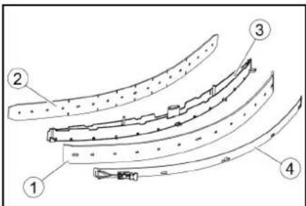
① Strgalna ustnica
②Podporna ustnica
③ Notranji del sesalnega prečnika
④Napenjalni trak
-
Obrnjene ali nove sesalne nastavke pritisnite na čepke notranjega dela sesalnega prečnika.
-
Namestite napenjalni trak.
-
Notranji del sesalnega prečnika potisnite v zgornji del.
-
Privijte zvezdasta ročaja in ju zategnite.
① Sito za grobo umazanijo
② Sito za kosme
2. Sito za grobo umazanijo odstranite v smeri navzgor.
3. Sperite sito za grobo umazanijo pod tekočo vodo.
4. Vstavite sito za grobo umazanijo v rezervoar za umazano vodo.
1. Odprite pokrov rezervoarja za odpadno vodo.
Čiščenje plovca in filtra za kosme
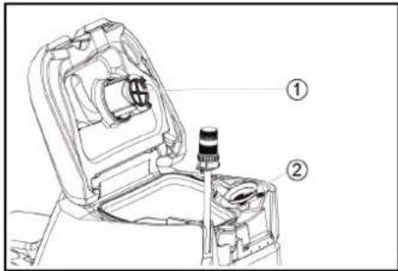
①Plovec
②Filter za kosme
2. Plovec sperite s čisto vodo.
3. Odstranite in očistite filter za kosme.
Zamenjava kolutne krtače
Napotek
①Filter za svežo vodo
②Zapiralo rezervoarja za svežo vodo
2006/42/ES (+2009/127/ES)
2014/30/EU
2014/53/EU (TCU)

H. Jenner
Chairman of the Board of Management

S. Reiser
Director Regulatory Affairs & Certification
① Claxonul
natural_image
Technical line drawing of a mechanical or industrial robotic platform with no visible text or symbols
natural_image
Line drawing of a truck with wheels and a roof, no text or symbols present①Maneta de deblocare
natural_image
Technical line drawing of a mechanical assembly with pulleys and wheels (no text or symbols)① Piuliţă
②Saiba platä
natural_image
Diagram of a hand connecting a flexible hose to a device with directional arrows indicating movement (no text or symbols)natural_image
Top-down schematic of a car interior with structural components and an inset view of the dashboard (no text or labels)Depozitarea
△PRECAUTIE
①Flotor
② Filtru de puf
Directive UE relevante
2006/42/UE (+2009/127/UE)
2014/30/UE
2014/53/UE (TCU)
Chairman of the Board of Management

S. Reiser
Director Regulatory Affairs & Certification
71364 Winnenden (Germania)
Tel.: +49 7195 14-0
Fax: +49 7195 14-2212
Winnenden, /09/01
Sadržaj
Opće napomene 212
Funkcija.... 212
① Sirena
①Remen
②odbor
③Prijava
④ Drveni blok
-
Odvijte blokove, kvadrate i ploče. Komponente za odvrtanje su na slici označene sivom bojom.
-
Ispred palete postavite rampu s odvijenim pločama i četverokutom drveta i pričvrstite ih vijcima za ivericu.
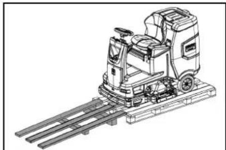
natural_image
Line drawing of a mechanical cleaning or inspection machine with no visible text or symbols①Usisno crijevo
① Utikač baterije, strana uređaja
② Utikač baterije, strana baterije
-
Spojite konektor baterije na strani baterije na punjač.
-
Útaknite utikač punjača u utičnicu.
-
Provedite postupak punjenja u skladu s uputama za uporabu punjača.
-
Spojite konektor baterije na strani uređaja na konektor baterije na strani baterije.
-
Okrenite spremnik otpadne vode prema naprijed i zatim ga zatvorite.
Akumulatori koji ne zahtijevaju održavanje (elektrolitski akumulatori)
△OPASNOST
① Otključavajuća poluga
-
Umetnite novčić između kućišta i poluge na oba kra- ja poluge.
-
Otpustite ručicu za otpuštanje.
-
Gurnite uređaj.
-
Izvadite obje kovanice odmah nakon guranja.
Podesite sjedalo
Postavite položaj
-
Pritisnite ručicu za podešavanje sjedala i pomaknite sjedalo u željeni položaj.
-
Otpustite ručicu za podešavanje sjedala i učvrstite sjedalo.
natural_image
Technical line drawing of a mechanical assembly with pulleys and gears (no text or symbols)①Vijak
② Matica
③Razina vode
- Otpustite maticu.
- Podesite vijak tako da indikator razine bude između dvije linije.
- Zategnite maticu.
- Da biste provjerili novu postavku, ponovo pomaknite uređaj na kratku udaljenost. Po potrebi ponovite postupak podešavanja.
- Prekidač s ključem okrenite u položaj 0/OFF.
Podešavanje visine
Podešavanje visine utječe na zakrivljenost gumica za usisavanje pri kontaktu s podom.
Napomena
① Matica
②Podloška
natural_image
Diagram showing a cable being inserted into a device with arrows indicating direction (no text or symbols)①Poklopac spremnika prljave vode
②Nastavci
③Stupanj
5. Ako je potrebno, napunite akumulator.
Sivi inteligentni ključ
Sivi inteligentni ključ daje nadzornom osoblju proširena odobrenja i mogućnosti postavljanja.
- Umetnite inteligentni ključ.
- Pomoću gumba s informacijama odaberite željenu funkciju.
Transportna vožnja
-
Postavite skloplku za odabir na „TRANSPORT MODE”.
-
Pritisnite gumb za informacije.
Sljedeće funkcije mogu se izvršiti iz TRANSPORT MODE izbornika:
• Postavljanje maksimalne brzine
• Prikaz brojača radnih sati
• Brisanje brojača održavanja
- Prikaz verzija softvera
- Podešavanje R ili D glave za čišćenje
• Postavljanje vremena naknadnog rada
• Postavljanje jezika
- Upravljanje ključem
- Aktiviranje tvorničke postavke
Maksimalna brzina
natural_image
Top-down schematic of a car interior with dashboard and steering wheel (no text or labels)Skladištenje
△OPREZ
Nepridržavanje težine
①Zvjezdasta ručka
② Zatezna traka
①Gumica za struganje
②Potporna gumica
① Mrežica za grubu prljavštinu
② Mrežica za skupljanje vlakana
2. Mrežicu za grubu prljavštinu izvadite prema gore.
3. Mrežicu za grubu prljavštinu isperite pod tekućom vodom.
4. Umetnite mrežicu za grubu prljavštinu u spremnik prljave vode.
①Plovak
②Filtar za dlačice
-
Isperite plovak čistom vodom.
-
Izvadite i očistite filtar za dlačice.
2006/42/EZ (+2009/127/EZ)
2014/30/EU
2014/53/EU (TCU)

H. Jenner
Chairman of the Board of Management
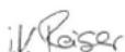
S. Reiser
Director Regulatory Affairs & Certification
Opunomoćenik za dokumentaciju:
S. Reiser
Alfred Kärcher SE & Co. KG
Alfred-Kärcher-Str. 28 - 40
71364 Winnenden (Njemačka)
Tel.: +49 7195 14-0
Telefaks: +49 7195 14-2212
Winnenden, 01.09..
Sadržaj
Opšte napomene 222
Funkcija.... 222
Namenska upotreba.... 222
①Poklopac rezervoara za svežu vodu sa filterom za svežu vodu
② Grubi filter za prljavštinu
③Poklopac rezervoara za otpadnu vodu
④ Kontrolna tabla
① Sirena
②Prekidač za smer vožnje
③Programski prekidač
④ Inteligentni ključ
⑤ Ekran
⑥Dugme za informacije
⑦ Sigurnosni prekidač
①Zatezna traka
②Tabla
③ Drveni blok
④ Drvena kocka
-
Odvijte drveni blok, drvene kocke i daske. Komponente za odvrtanje su na slici označene sivom bojom.
-
Napravite rampu ispred palete od odvrnutih dasaka i drvenih kocki i pričvrstite je pričvrsnim zavrtnjima
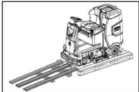
natural_image
Technical line drawing of a mechanical cleaning or inspection machine (no text or symbols)-
Montirajte baterije, ukoliko je uređaj isporučen bez baterija (pogledajte poglavlje „Pre puštanja u pogon/baterije“).
-
Uređaj vozite unapred sa palete (pogledajte poglavlje „Rad/vožnja“).
① Usisno crevo
① Utikač za bateriju, na uređaju
② Utikač za bateriju, na bateriji
3. Povežite priključak baterije na bateriji sa punjačem.
4. Utaknite mrežni utikač punjača u utičnicu.
5. Punite uredaj u skladu sa uputstvom za upotrebu punjača.
6. Povežite priključak baterije na uređaju sa priključkom baterije na bateriji.
7. Okrenite rezervoar za otpadnu vodu napred, a zatim ga zatvorite.
Akumulatori sa malim stepenom održavanja
(elektrolitski akumulatori)
△OPASNOST
Dopunjavanje vode u ispražnjenom stanju akumulatora
①Poluga za deblokadu
-
Na oba kraja poluge stavite kovanicu između kućišta i poluge.
-
Otpustite polugu za deblokadu.
-
Gurnite uređaj.
-
Izvadite obe kovanice odmah nakon postupka guranja.
Podešavanje sedišta
| maintenance |
| squeegee |
Očistite usisnu konzolu.
| Ekran Radnja | |
| maintenance brush head | Proverite da li su četke istrošene i očistite ih. |
| maintenance squeegee blade | Proverite da li su gumice za usisavanje istrošene i kako su podešene. |
| maintenance turbine filter | Očistiti mrežicu za skupljanje vlakana. |
| maintenance fresh water filter | Očistiti filter za svežu vodu. |
-
Pritisnite dugme za informacije.
-
Resetujle brojač za odgovarajuće održavanje (pogledajte „Resetovanje sivog Intelligent Key-a/brojača održavanja“).
Napomena
natural_image
Technical line drawing of a mechanical assembly with pulleys and wheels (no text or symbols)①Zavrtanj
②Navrtka
③Vaser-vaga
①Navrtka
②Podloška
natural_image
Diagram showing a hand holding a flexible hose with arrows indicating force or movement (no text or symbols)- Stisnite kraj creva i spustite ga preko uređaja za suzbijanje pene.
- Regulišite jačinu mlaza prljave vode stiskanjem kraja creva.
- Rezervoar za prljavu vodu isprati čistom vodom.
- Zatvorite poklopac na ispusnom crevu.
- Gurnite crevo za prljavu vodu u držač na uređaju
Ispraznite kontejner za grubu prljavštinu
- Podignite kontejner za grubu prljavštinu i izvucite ga.
- Ispraznite kontejner za grubu prljavštinu.
- Ponovo stavite kontejner za grubu prljavštinu.
Ispuštanje sveže vode
- Otvorite zatvarač rezervoara za svežu vodu.
- Ispustite svežu vodu.
- Očistite filter.
- Stavite zatvarač rezervoara za svežu vodu.
Odlaganje uređaja
- Okrenite programski prekidač u položaj „OFF”.
- Izvucite Intelligent Key.
- Osigurajte uređaj od otkotrljavanja.
- Otvorite poklopac rezervoara za prljavu vodu i pričvrstite ga nosačem kako bi rezervoar za prljavu vodu mogao da se osuši. Da biste to učinili, spustite nastavak prema dolje i postavite donji kraj na željeni nivo prilikom pomeranja poklopca prema dole.
①Poklopac rezervoara za prljavu vodu
②Nastavci
③ Stepen
5. Po potrebi, napuniti bateriju.
Sivi Intelligent Key
Sivi Intelligent Key daje nadzornom osoblju dodatna ovlašćenja i mogućnosti za podešavanja.
1. Utaknite Intelligent Key.
2. Izaberite željenu funkciju okretanjem dugmeta za informacije.
Transportna vožnja
- Postavite prekidač za izbor programa na „TRANSPORT MODE“.
-
Pritisnite dugme za informacije.
Sledeće funkcije se mogu izvršiti iz TRANSPORT MODE menija: -
Podešavanje maksimalne brzine
• Prikaz brojača radnih sati
• Brisanje brojača održavanja - Prikaz verzija softvera
- Podešavanje R ili D glave za čišćenje
- Podešavanje vremena posle rada
- Podešavanje jezika
• Upravljanje ključevima - Aktiviranje fabričkog podešavanja
Maksimalna brzina
U meniju „max speed“ može da se ograniči radna brzina.
- Okrećite dugme za informacije dok se na ekranu ne prikaže „max speed“.
- Pritisnite dugme za informacije.
- Okrećite dugme za informacije dok se ne prikaže željena maksimalna brzina.
- Pritisnite dugme za informacije.
Napomena
Radna brzina ne može da premaši podešenu maksimalnu brzinu.
natural_image
Top-down technical sketch of a car interior with structural components and dashboard (no text or labels)Skladištenje
△OPREZ
1 Zvezdasta ručka
②Zatezna traka
③Unutrašnji deo usisne konzole
④ Zatezna brava
-
Izvucite unutrašnji deo usisne konzole.
-
Otvorite zateznu bravu.
-
Skinite zateznu traku.
-
Otpustite gumice za usisavanje sa unutrašnjeg dela.
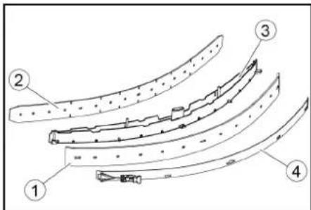
① Gumice za prikupljanje prljavštine
② Dodatna gumica
③Unutrašnji deo usisne konzole
④Zatezna traka
-
Korišćene ili nove gumice za usisavanje gurnite na klinove unutar usisne konzole.
-
Stavite zateznu traku.
- Gurnite unutrašnji deo usisne konzole u gornji deo.
- Zaviti i pričvrstiti zavrtnjima zvezdaste ručice.
Čišćenje mrežice za grubu prljavštinu
- Otvoriti poklopac rezervoara za prljavu vodu.
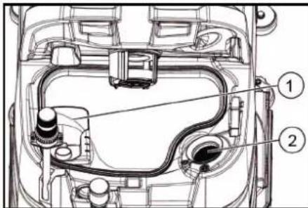
① Mrežica za grubu prljavštinu
② Mrežica za skupljanje vlakana
2. Mrežicu za grubu prljavštinu skinuti prema gore.
3. Mrežicu za grubu prljavštinu isprati pod mlazom vode.
4. Mrežicu za grubu prljavštinu umetnuti u rezervoar za prljavu vodu.
Čišćenje plovka I filtera za vlakna
- Otvorite poklopac rezervoara za otpadnu vodu.
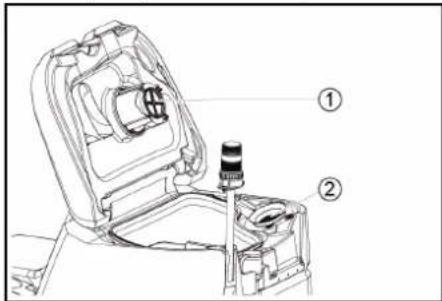
①Plovak
②Filter za vlakna
-
Isperite plovak čistom vodom.
-
Uklonite i očistite filter za vlakna.
① Ručka za zamenu četki
②Poklopac skladišta sa gumicom za prikupljanje prljavštine
③ Valjkasta četka
- Skinite poklopac skladišta sa gumicama za prikupljanje prljavštine.
- Izvucite valjkastu četku.
- Stavite novu valjkastu četku i centrirajte je na obrtaču.
①Prihvatnik
②Prihvatni trn
O
2006/42/EZ (+2009/127/EZ)
2014/30/EU
2014/53/EU (TCU)
Chairman of the Board of Management
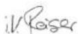
S. Reiser
Director Regulatory Affairs & Certification
Lice ovlašćeno za dokumentaciju:
S. Reiser
Alfred Kärcher SE & Co. KG
Alfred-Kärcher-Str. 28 - 40
71364 Winnenden (Germany)
Tel.: +49 7195 14-0
①μάντας
② Σανίδα
③Tákos
④Καδρόνι
natural_image
Technical line drawing of a mechanical or industrial robotic platform with no visible text or symbols
natural_image
Line drawing of a truck with front wheel and side-mounted equipment, no text or symbols present①Απασφάλιση μοχλού
natural_image
Technical line drawing of a mechanical assembly with pulleys and gears (no text or symbols)natural_image
Diagram showing a cable being inserted into a device with arrows indicating direction (no text or symbols)Αποθήκευση
ΔΠΡΟΣΟΧΗ
H. Jenner
Chairman of the Board of Management

S. Reiser
Director Regulatory Affairs & Certification
71364 Winnenden (Germany)
Tηλ.: +49 7195 14-0
Φαξ: +49 7195 14-2212
Winnenden, /09/01
Содержание
Общие указания 243
natural_image
Technical line drawing of a mechanical cleaning or inspection machine with no visible text or symbols①Всасывающий шланг
natural_image
Line drawing of a vehicle with a steering wheel and dashboard, no text or symbols presentnatural_image
Technical line drawing of a mechanical assembly with pulleys and gears (no text or symbols)①ВИНТ
②Гайка
③Нивелир
①Гайка
②Подкладочная шайба
natural_image
Diagram of a medical device with a coiled tube and directional arrows indicating movement or force (no text or symbols)Хранение
△ОСТОРОЖНО
Несоблюдение веса
①Звуковий сигнал
① Стяжна стрічка
②Дошка
③Колодка
④ Дерев'яний брус
natural_image
Technical line drawing of a mechanical cleaning or inspection machine on a platform (no text or symbols visible)natural_image
Technical line drawing of a mechanical assembly with pulleys and gears (no text or symbols)① ГВИНТ
②Гайка
③Водяний рівень
①Гайка
②Підкладна шайба
natural_image
Diagram showing a hand connecting a plastic tray with a coiled hose, indicating fluid or electrical connection (no text or symbols present)natural_image
Top-down technical diagram of a car's front and side views, showing engine, dashboard, and dashboard components (no text or labels)Зберігання
△ОБЕРЕЖНО
Недотримання ваги

H. Jenner
Chairman of the Board of Management
S. Reiser
Director Regulatory Affairs & Certification
71364 Winnenden (Germany)
Тел.: +49 7195 14-0
Факс: +49 7195 14-2212
natural_image
Technical line drawing of a mechanical cleaning or inspection machine on a platform (no text or symbols visible)natural_image
Technical line drawing of a mechanical assembly with pulleys and gears (no text or symbols)①ВИНТ
②Гайка
③ Ниво на водата
①Гайка
②Подложна шайба
natural_image
Diagram showing a hand holding a flexible hose connected to a device with directional arrows indicating movement (no text or symbols)natural_image
Top-down technical diagram of a car's front and rear views, showing structural components without any text or labels.Съхранение
⚠ПРЕДПАЗЛИВОСТ
①Поплавък
H. Jenner
Chairman of the Board of Management
S. Reiser
Director Regulatory Affairs & Certification
71364 Winnenden (Germany)
Тел.: +49 7195 14-0
Факс: +49 7195 14-2212
Виненден, /09/01
目录
一般性注意事项.... 276
功能.... 276
按规定使用 276
环境保护 276
附件和备件.... 276
供货范围 276
安全提示…… 276
设备说明.... 278
安装 279
投入运行.... 279
运行 280
结束运行.... 281
灰色智能钥匙 281
运输.... 281
储存.... 282
保养和维护 282
故障排除.... 283
质量保证.... 284
配件 284
技术数据.... 284
欧盟一致性声明 285
般性注意事项
www.kaercher.com/REACH
附件和备件
①清水箱封盖,水箱配备清水过滤器
②粗大污垢滤网
③污水箱盖罩
④控制面板
⑤削刮胶条调节轮(仅 D 清洁头)
⑥换刷踏板
⑦方向盘
⑧削刮胶条
⑨电池
⑩铭牌
⑪座椅调节杆
⑫清洁套件“Homebase Box”的存放区域
⑬*警告灯
⑭座椅
⑮污水箱解锁件
⑯清水箱加注口
⑰软管支架
⑱门问行驶灯
⑲油门踏板
20浮子
21细滤网
22污水排放软管
23污水箱
24*拖把架
25抽吸软管
26吸水扒夹紧杆
⑳污水箱封盖
28吸水扒
29清洁头
30清水液位表
③1清水箱
* 可选
颜色标记
- 清洁过程的操作元件为黄色
- 保养和检修的操作元件为浅灰色。
控制面板
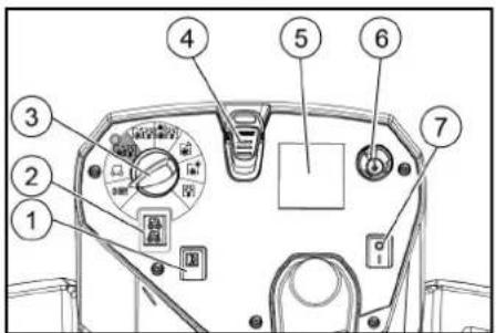
①喇叭
②行进方向开关
③程序开关
④智能钥匙
⑤*显示屏
⑥信息按钮
⑦安全开关
①紧固带
②板
③底座
④方木
natural_image
Technical line drawing of a mechanical cleaning or inspection machine with railings (no text or symbols)①电池插头,设备侧
②电池插头,电池侧
natural_image
Line drawing of a vehicle with a spotlight and roof, no text or symbols present①解锁杆
natural_image
Technical line drawing of a mechanical assembly with pulleys and wheels (no text or symbols)①螺栓
②螺母
③水平仪
①螺母
②垫片
③间隔滚轮与支架
natural_image
Diagram showing a hand holding a flexible hose connected to a device with directional arrows indicating movement (no text or symbols present)①污水箱盖罩
②支架
③等级
- 必要时给电池充电。
灰色智能钥匙
natural_image
Top-down technical diagram of a car's front and rear views, showing engine, dashboard, and structural components (no text or labels)储存
△ 小心
忽视重量
受伤与损坏危险
存放时注意设备的重量。
注意
霜冻
冻住的水导致设备损坏
彻底排空设备中的水。
将设备保管在无霜冻的地方。
- 本设备只允许存放在室内。
- 长时间存放之前,要给电池完全充电。
①星形手柄
②紧固带
③吸水扒内置件
④紧固封盖
①削刮胶条
②支撑胶条
③吸水扒内置件
④紧固带
①粗大污染物滤网
②细滤网
①浮子
②细滤网
-
用清水冲洗浮子。
-
取下细滤网并清洗。
更换刷盘
提示
①换刷手柄
②带削刮胶条的轴承盖
③刷辑
①清水过滤器
②清水箱密封盖
①警笛
①ストラップ
②ボード
③ブロック
④ビーム
natural_image
Technical line drawing of a mechanical cleaning or inspection machine with no visible text or symbols①サクションホース
②サクションバーサスペンション
③サクションバー
④クランプレバー
natural_image
Line drawing of a truck with wheels and a sensor array, no text or symbols present①ロック解除レバー
natural_image
Technical line drawing of a mechanical assembly with pulleys and gears (no text or symbols)①ネジ
②ナット
③水準器
①ナット
②ワッシャー
③ホルダー付きスペーサーローラー
natural_image
Diagram of a medical device with a coiled tube and directional arrows indicating movement or force (no text or symbols)①発水タンクキャップ
②サボート
③レベル
natural_image
Top-down schematic of a car interior with labeled components and an inset photo showing a dashboard (no text or symbols present)保管
注意
重量無視
怪我ならびに損傷の危険
①スターハンドル
②ストラップ
③サクションバーの内側
④テンションロック
① ワイパーリップ
②サポートリップ
③サクションバーの内側
④ストラップ
①祖目の汚れフィルター
②綿毛フィルター
①フロート
②綿毛フィルター
①ブラシ交換ハンドル
②スキージブレード付きベアリングカバー
③コーラープラシ
2006/42/EG (-2009/127/EG)
2014/30/EU
2014/53/EU (TCU)
整合規格の適用
EN 60335-1
EN 60335-2-29
EN 60335-2-72
EN 62233: 2008
EN 55012: 2007 + A1: 2009
EN 61000-3-2: 2014
EN 61000 3 3: 2013
EN 61000-6-2: 2005
EN 61000-6-3:2007 + A1:2011
TCU(テレマティクス制御ユニット)
EN 301 511 V12.5.1
EN 300 440 V2.1.1
EN 300 328 V2.2.2
EN 300 330 V2.1.1
使用国の規格
H. Jenner
Chairman of the Board of Management
S. Reiser
Director Regulatory Affairs & Certification
文書の全権委員:
S. Reiser
Alfred Kärcher SE & Co. KG
Alfred Kärcher Str. 28 40
71364 Winnenden (Germany)
電話番号:+49 7195 14-0
2006/42/EG (-2009/127/EG)
2014/30/EU
2014/53/EU (TCU)
整合規格の適用
EN 60
EN 60335-2-29 EN 60335-2-72 EN 62233: 2008 EN 55012: 2007 + A1: 2009 EN 61000-3-2: 2014 EN 61000-3-3: 2013 EN 61000-6-2: 2005 EN 61000 6 3: 2007 + A1:2011 TCU (テレマティクス制御ユニット) EN 301 511 V12.5.1 EN 300 440 V2.1.1 EN 300 328 V2.2.2 EN 300 330 V2.1.1
使用国の規格

H. Jenner
Chairman of the Board of Management
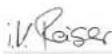
S. Reiser
Director Regulatory Affairs & Certification
文書の全権委員:
S. Reiser
Alfred Kärcher SE & Co. KG
Alfred-Kärcher-Str. 28 - 40
71364 Winnenden (Germany)
電話番号:-49 7195 14-0
①경유기
②이동 방향 스위치
③프로그램 스위치
④인텔리전드 키
⑤*디스플레이
⑥징보 버튼
⑦안전 스위치
①고징 멜드
②豆豆
③분목
④각목
- CAPS, GARMS, GARMS, GARMS, GARMS, GARMS, GARMS, GARMS, GARMS, GARMS, GARMS, GARMS, GARMS, GARMS, GARMS, GARMS, GARMS, GARMS, GARMS, GARMS, GARMS, GARMS, GARMS, GARMS, GARMS, GARMS, GARMS, GARMS, GARMS, GARMS, GARMS, GARMS, GARMS, GARMS, GARMS
4.나사를 폰 보드 및 각목과 함께 경사로를 팔레드 잎 에 매치하고 합관 나사로 고성하십시오.
natural_image
Line drawing of a mechanical cleaning or inspection machine with no visible text or symbols① Tunisia호스
②신공바 현가장치
③진공바
④조인 레버
①배터리 풀러그, 기기 측
②베터리 플러그,베터리 측
①해제 레버
natural_image
Technical line drawing of a mechanical assembly with pulleys and gears (no text or symbols)①+사
②나트
③의던계
①니드
②와서
③홈디가 포함된 스페이서 롤리
natural_image
Diagram showing a hand holding a flexible hose connected to a device with arrows indicating force or movement (no text or symbols present)①데수 텝크 뭉킹
②지지부
③단계
5.필요시배터리를종진합니다.
회색 인텔리전트 키
natural_image
Top-down technical diagram of a car interior with structural components and dashboard (no text or labels)보관
△ 주의
무게 미준수
부상 및 손상 위험
①스타그림
②고징 멜드
③진공바 내측 부분
④걸쇠형 산규장치
①바이징 플랜
②서포트 림
③진공바 내측 부분
④고정 멘트
①론 오염날 제
②보품 필터
①
②보품 필터
- 깨끗한 물로 플로드를 헬给您니다.
①정수 펀터
②정수 맵크 잠규장치

H. Jenner
Chairman of the Board of Management
S. Reiser
Director Regulatory Affairs & Certification
문시 작성 책임사:
S. Reiser
Alfred Kärcher SE & Co. KG
Alfred-Kärcher-Str. 28 - 40
71364 Winnenden (Germany)
전화:+49 7195 14-0
필소: +49 7195 14-2212
Winnenden, /09/01
EN 61000-3-2: 2014
EN 61000-3-3: 2013
EN 61000-6-2: 2005
EN 61000-6-3: 2007 + A1:2011
TCU
EN 301 511 V12.5.1
EN 300 440 V2.1.1
EN 300 328 V2.2.2
EN 300 330 V2.1.1
Chairman of the Board of Management
S. Reiser
Director Regulatory Affairs & Certification
وكيل التويّق:
اس رايزر
Alfred Kärcher SE & Co. KG
Alfred-Kärcher-Str. 28 - 40
71364 Winnende
m = 311
ف
.
1
2
1
1
|
|
|
|
|
1
2
3
4
3
3
□
1
1
.
1
1
1
1
1
②
©
-
[Unreadable]
9
[Non-Text]
1
[Non-Text]
[Non-Text]
[Non-Text]
[Non-Text]
[Non-Text]
[Non-Text]
[Non-Text]
[Non-Text]
[Non-Text]
[Non-Text]
[Non-Text]
•
:
•
•
[Non-Text]
[Non-Text]
项目
•
[Unreadable]
يم
项目
m = 311
2.
2
1
1
|
|
|
|
|
□
5
©
4
3
5
□
1
1
1
1
1
)
-
1
②
⑤
[Non-Text]
(1)
9
[Non-Text]
1
[Non-Text]
②
⑤
[Non-Text]
(1)
m = 311
-
[Non-Text]
[Non-Text]
[Non-Text]
[Non-Text]
[Non-Text]
[Non-Text]
[Non-Text]
[Non-Text]
[Non-Text]
[Non-Text]
•
:
•
•
项目
•
附件
يم
项目
m = 311
2.
2
:
•
•
[Non-Text]
项目
•
附件
يم
يم
2
a
1
|
|
|
|
|
©
2
3
4
4
3
7
1
|
4
1
1
1
-
5
2
4
.7
8
10
1
[Non-Text]
[Non-Text]
[Non-Text]
[Non-Text]
[Non-Text]
[Non-Text]
[Non-Text]
[Non-Text]
[Non-Text]
[Non-Text]
[Non-Text]
•
:
•
•
•
[Non-Text]
2017
广力云智慧零售收银系统
m = 311
و
The image is too blurry to recognize any text content.
فر
1
-
41
|
|
|
|
|
|
1
②
①
1.2.3
4
6
1
1
1
21
1
1
|
2
©
3
4)
. f
。
10
1
[Non-Text]
[Non-Text]
[Non-Text]
©
3
4)
. f
。
-
广力云
[Non-Text]
[Non-Text]
[Non-Text]
[Non-Text]
[Non-Text]
[Non-Text]
[Non-Text]
[Non-Text]
[Non-Text]
[Non-Text]
(No text)
•
(1)
•
[Non-Text]
-
•
[Non-Text]
m = 311
[Non-Text]
m = 311
q
1
.
1
-
41
|
|
|
|
©
3
4)
. f
m = 311
广力云
[Non-Text]
[Non-Text]
[Non-Text]
[Non-Text]
[Non-Text]
[Non-Text]
[Non-Text]
[Non-Text]
•
:
•
项目
•
[Unreadable]
يم
:
•
•
[Non-Text]
项目
•
[Unreadable]
- Information of delay times "I" (1)
الشاه.
natural_image
Diagram showing a hand connecting a plastic tray with a coiled hose, indicating fluid or mechanical connection (no text or symbols present)natural_image
Technical line drawing of a mechanical assembly with pulleys and gears (no text or symbols)① برغي
② صامولة
③ ميزان ماني
5 حل الصامولة.
① صامولة
② فلكة

natural_image
Line drawing of a truck with wheels and a side-mounted mast, shown in perspective view (no text or symbols)① ذراع التحرير
①. جاني الجها
② Grenp الطارية
بالشاحن.
- نب البطارية
في المقياس 4
natural_image
Technical line drawing of a mechanical cleaning or inspection machine with no visible text or symbols① خرطوم شفط
② تعليم كمرة الشفط
③ كمرة الشفط
④ دراع thyبيت
جزام ①
②
③ قرمة
④ خشبة مربعة
① ر المياء العذبة
② شواني الخشنة
③ياء المستعملة
④لوحة التحكم
⑤ رأس التنظيف
(فقط)
⑥ تبدأ الفرشاة
⑦ عجلة القيادة
⑧ حواجز جانیه
⑨البطارية*
⑩لوحة النوع
⑪ تعديل المqedد
① أداةorerه
② مفتاح اتجاه السير
③ مفتاح البرنامج
④ المفتاح الذكي
الشاه * ⑤
⑥ زر المعلومات
⑦ مفتاح الأمن
•Should the shopping.
natural_image
Black and white line drawing of a hand giving a thumbs-up gesture (no text or symbols)THANK YOU!
Register your product and benefit from many advantages.
www.kaercher.com/welcome


Rate your product and tell us your opinion.
natural_image
Icon showing a gear and wrench inside a square frame (no text or symbols)www.kaercher.com/dealersearch
Alfred Kärcher SE & Co. KG
Alfred-Kärcher-Str. 28-40
71364 Winnenden (Germany)