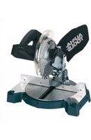
KS 210/2 Profi - Saw Alpha Tools - Free user manual and instructions
Find the device manual for free KS 210/2 Profi Alpha Tools in PDF.


User questions about KS 210/2 Profi Alpha Tools
0 question about this device. Answer the ones you know or ask your own.
Ask a new question about this device
Download the instructions for your Saw in PDF format for free! Find your manual KS 210/2 Profi - Alpha Tools and take your electronic device back in hand. On this page are published all the documents necessary for the use of your device. KS 210/2 Profi by Alpha Tools.
USER MANUAL KS 210/2 Profi Alpha Tools
natural_image
Mechanical device with metallic components and a transparent circular component (no visible text or symbols)ks 210/2 Profi
© Bitte Seite 2-5 ausklappen
Please pull out pages 2-5
© Veuillez ouvrir les pages 2 à 5
© Gelieve bladzijden 2-5 te ontvouven
E Por favor desdoble las paginas de 2 a 5
© Desdobre as páginas 2-5
⑤ Var vänlig öppna sidorna 2-5
© Käännä sivut 2-5 auki
N Fold ut 2-5
© Παρακαλούμε ξεδιπλώσετε τις σελίδες 2-5.
① Aprire le pagine dalle 2 alla 5
© Fold side 2-5 ud
PL Prosze 2-5
text_image
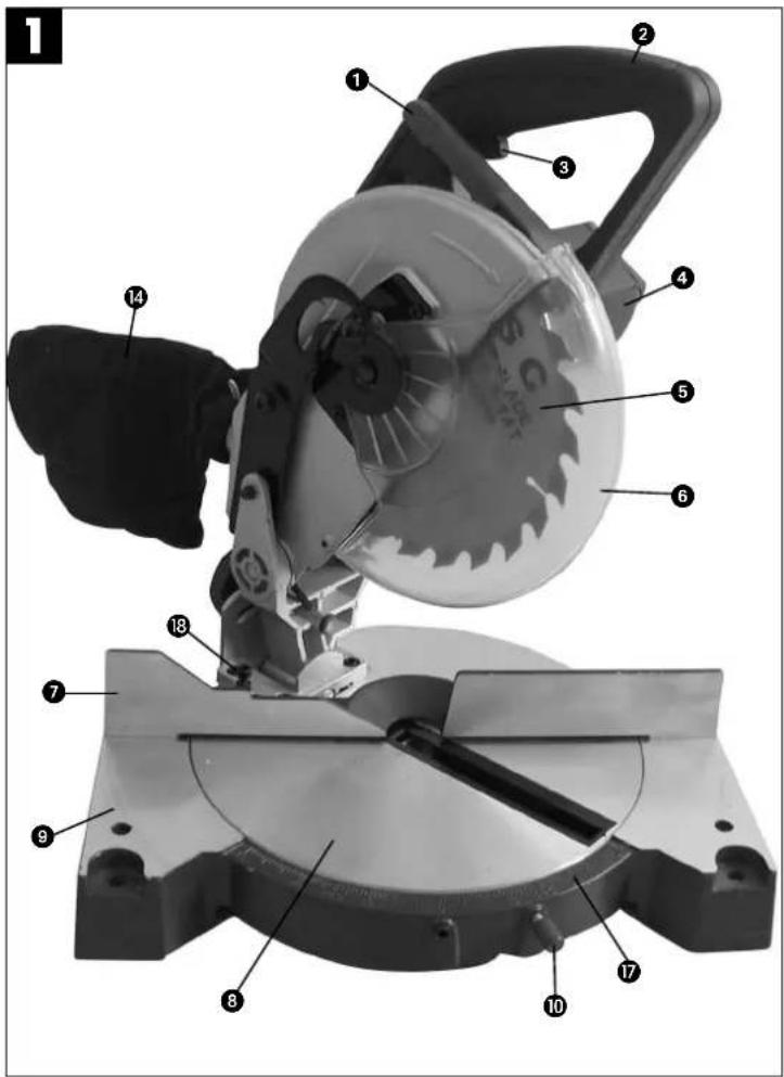
Labeled diagram of a cutting tool with numbered parts for identification3
text_image
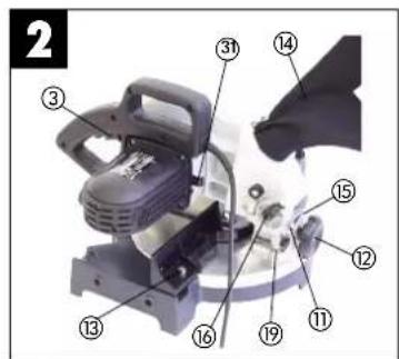
2 ③ ③1 ⑭ ⑭ ⑮ ⑮ ⑫ ⑫ ⑫ ⑬ ⑯ ⑪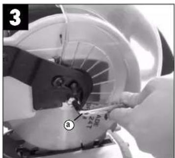
natural_image
Close-up of a mechanical device with a tool and labeled component (no readable text or symbols)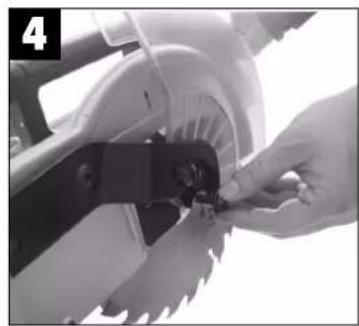
natural_image
Close-up of hands using a saw blade to cut the blade (no text or symbols visible)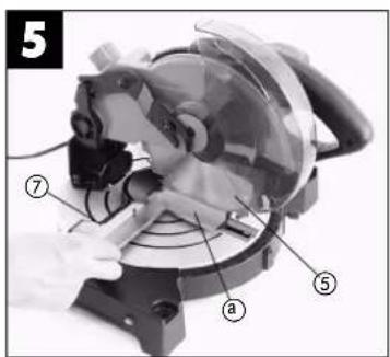
text_image
5 ⑦ ⑤ a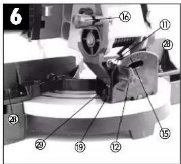
text_image
6 ① ② ③ ④ ⑤ ⑥ ⑦ ⑧ ⑨ ⑩ ⑪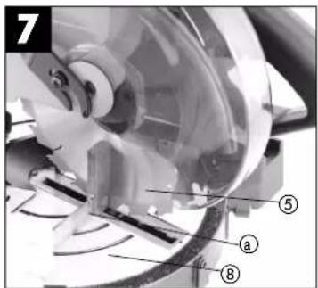
text_image
7 ⑤ a ⑧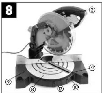
text_image
8 ② ⑨ ⑧ ⑩ ⑰ ① a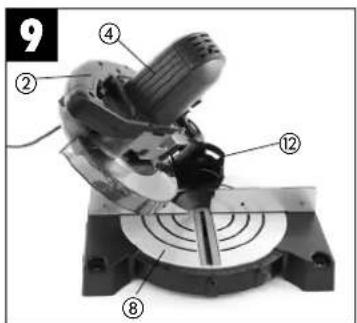
text_image
9 ② ④ ⑫ ⑧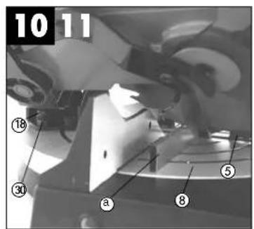
text_image
10 11 ⑱ ③ a ⑤ 8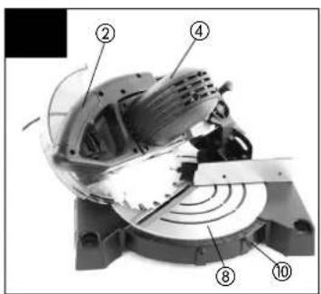
text_image
Technical diagram of a mechanical device with numbered components labeled ②, ④, ⑧, and ⑩.D
- Release button
- Handle
- On/Off switch
- Machine head
- Saw blade
- Saw blade guard, hinged
- Stop rail
- Rotary table
- Base plate, fixed
- Locking handle
- Pointer
- Locking nut
- Fixing screw
- Chip bag
- Scale
- Retaining pin
- Scale (turntable)
- Adjusting screw 45°
- Adjusting screw 90°
2. Items supplied
● Carbide-tipped saw blade
- Socket wrench (20)
● Cross-cut and mitre saw
● Blade guard (6)
3. Proper use
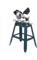
The KS 210/2 Profi circular cross-cut and mitre box saw is designed for the cross-cutting of timber and plastic commensurate with the machine's size.
The machine is not to be used for cutting fire wood. The machine is to be used only for its prescribed purpose.
Any use other than that mentioned is considered to be a case of misuse. The user/operator and not the manufacturer shall be liable for any damage or injury resulting from such cases of misuse.
The machine is to be operated only with suitable saw blades. It is prohibited to use any type of cutting-off wheel.
To use the machine properly you must also observe the safety regulations, the assembly instructions and the operating instructions to be found in this manual. All persons who use and service the machine have to be acquainted with this manual and must be informed about its potential hazards.
It is also imperative to observe the accident prevention regulations in force in your area.
The same applies for the general rules of occupational health and safety.
The manufacturer shall not be liable for any changes
made to the machine nor for any damage resulting from such changes.
Even when the machine is used as prescribed it is still impossible to eliminate certain residual risk factors. The following hazards may arise in connection with the machine's construction and design:
- Contact with the saw blade in the uncovered saw zone.
● Reaching into the running saw blade (cut injuries).
● Kick-back of workpieces and parts of workpieces.
● Saw blade fracturing.
● Catapulting of faulty carbide tips from the saw blade.
● Damage to hearing if essential ear-muffs are not worn.
● Harmful emissions of wood dust when the machine is used in closed rooms.
4. Important notes
Please read this manual carefully and pay attention to the information provided. Use this manual to familiarize yourself with the machine, its correct use and safety regulations.

Safety regulations
● Always pull the plug out of the power socket before adjusting or servicing the machine.
● Give these safety regulations to all persons who work on the machine.
● Do not use this saw to cut fire wood.
● Caution! Hands and fingers may be injured on the rotating saw blade.
● Before you use the machine for the first time, check that the voltage marked on the rating plate is the same as your mains voltage.
- If you need to use an extension cable, make sure its conductor cross-section is big enough for the saw's power consumption. Minimum cross-section: 1.5 mm ^2 .
- If you use a cable reel, the complete cable has to be pulled off the reel.
● Never carry the saw by its cable
- Do not leave the saw in the rain and never use it in damp or wet conditions.
● Provide good lighting
● Never saw near combustible liquids or gases.
- Wear suitable work clothes! Loose garments or jewellery may become caught up in the rotating saw blade.
GB
● Operators have to be at least 18 years of age. Trainees of at least 16 years of age are allowed to use the machine under supervision.
- Keep children away from the machine when it is connected to the power supply.
- Check the power cable (9). Never use a faulty or damaged power cable.
- Keep your workplace clean of wood scrap and any unnecessary objects.
● Persons working on the machine should not be distracted.
● Note the direction of rotation of the motor and saw blade.
● After you have switched off the motor, never slow down the saw blade by applying pressure to its side.
● Fit only blades which are well sharpened and have no cracks or deformations.
● The machine is to be operated only with tools which conform with prEN 847-1: 1996.
● Faulty saw blades have to be replaced immediately.
● Never use saw blades which do not comply with the data specified in this manual.
● Make sure that the arrow on the saw blade complies with the arrow marked on the machine.
- Make certain that the saw blade does not touch the rotary table in any setting. To do so, pull out the power plug and tilt the saw blade by hand into the 45° position and the 90° position.
If necessary, re-adjust the saw head as described in Section C/F.
- It is imperative to make sure that all the devices used to cover the saw blade are in good working order.
● Never wedge the hinged guard hood in open position.
- Never dismantle the machine's safety devices or put them out of operation.
● Damaged or faulty safety devices have to be replaced immediately.
● Never cut workpieces which are too small to hold securely in your hand.
- Do not place your hands in awkward positions where one or both may slip suddenly and touch the saw blade.
- When working with long workpieces, use an additional support (table, stand, etc.) to prevent the machine from tipping over.
● Always clamp round workpieces such as dowel rods etc. with suitable devices.
● There must be no nails or other foreign bodies in that part of the workpiece you want to cut.
● Always stand to the side of the saw blade when working with the saw.
● Never load the machine so much that it cuts out.
● Always press the workpiece firmly against the table and the stop rail to prevent it from wobbling or twisting.
● Make sure that off-cuts can be removed from the side of the saw blade. If not, they may catch on the saw blade crown and be catapulted into the surrounding area.
● Never saw several workpieces simultaneously.
● Never remove loose splinters, chips or jammed pieces of wood when the saw blade is running.
● To rectify faults or remove jammed pieces of wood, always switch off the machine first. - Pull out the power plug!
● Conversions, adjustments, measurements and cleaning jobs are to be performed only when the motor is switched off. - Pull out the power plug!
● Before you switch on the machine, check that all wrenches and adjustment tools have been removed.
- When you leave your workplace, switch off the motor and pull out the power plug.
● Electric installation work, repairs and maintenance are to be carried out only by specialists.
● All guards and safety devices have to be refitted immediately after completion of any repairs or maintenance.
- It is imperative to observe the manufacturer's safety, operating and maintenance instructions as well as the dimensions quoted in the technical data.
- It is imperative to observe the accident prevention regulations in force in your area as well as all other generally recognized rules of safety.
● Note the information published by your professional associations.(VBG7j)
- Switch on the dust extraction system each time you use the machine.
● The machine may be used in closed rooms only in conjunction with a suitable vacuum extraction system.
● The circular cross-cut must be connected to a 230 V socket-outlet with a minimum 10 A fuse.
● Never use light-duty machines for heavy-duty work.
● Never use the cable for any purpose other than that for which it is intended!
- Adopt a firm standing position and keep your balance at all times.
● Check the tool for signs of damage!
● Before you carry on using the tool it is imperative to check that its safety devices and any slightly damaged parts are working properly and in the way intended.
- Check that the moving parts work properly and do not jam or whether any of the parts are
GB
damaged. All parts must be fitted correctly and satisfy all conditions for the tool to work properly
● Unless otherwise stated in these instructions, damaged safety devices and parts must be repaired or replaced by experts in an approved specialist workshop.
● Have damaged switches replaced by a customer service workshop.
● This tool complies with the pertinent safety regulations. Repairs are to be carried out only by qualified electricians using original replacement parts. The user may suffer an accident if this condition is not observed.

Wear goggles

Wear ear-muffs

Wear a breathing mask
the number of machines and other neighbouring operations. Reliable workplace values may also vary from country to country. With this information the user should at least be able to make a better assessment of the dangers and risks involved."
5. Technical data
Asynchronous motor 230 V \~ 50 Hz
Power rating 1200 W
Operating mode S1
Idle speed n0 4200 rpm
Carbide saw blade 210×30×2.5 mm
Number of teeth 24
Standing area 390 x 300
Tilting range -45° / 0° / +45°
Mitre cuts 0° to 45° to the left
Saw bed support 385 x 140 mm
Sawing width at 90° 120 x 60 mm
Sawing width at 45° 84 x 60 mm
Sawing width at 2 x 45"
(double mitre cuts) 50 x 35 mm
Noise emission values
- The saw's noise is measured in accordance with DIN EN ISO 3744; 11/95, E Din EN 31201; 6/93, ISO 7960 Annex A; 2/95. The machine may exceed 85 dB(A) at the workplace. In this case, noise protection measures need to be introduced for the user (ear-muffs).
Cutting Idling
Sound pressure level LPA 104,4 dB(A) 94,2 dB(A)
Sound power level LWA 111,4 dB(A) 107,2 dB(A)
„The quoted values are emission values and not necessarily reliable workplace values. Although there is a correlation between emission and immission levels it is impossible to draw any certain conclusions as to the need for additional precautions. Factors with a potential influence on the actual immission level at the workplace include the duration of impact, the type of room, and other sources of noise etc., e.g.
6. Before putting the machine into operation
● The machine has to be set up where it can stand firmly, e.g. bolt it to a work bench, a universal base or similar.
● All the covers and safety devices have to be properly fitted before the machine is switched on.
- It must be possible for the saw blade to run freely.
- When working with wood that has been processed before, watch out for foreign bodies such as nails or screws etc.
- Before you actuate the On/Off switch, make sure that the saw blade is correctly fitted and that the machine's moving parts run smoothly.
● Before you connect the machine to the power supply, make sure the data on the rating plate is the same as that for your mains.
GB
7. Assembly
A.) Adjusting the saw (Fig. 1/2)
● To adjust the turntable (8), loosen the locking grip (10) by turning it through 2 complete rotations to unlock the turntable (8).
- The turntable (8) can be set to 0^ , 15^ , 22.5^ , 30^ and 45^ .
As soon as the turntable (8) has engaged, the position must be fixed by tightening the locking grip (10).
- If different angles are required, the turntable (8) is fixed using the locking grip (10) alone.
● While pressing down lightly on the machine head (4), pull the lock pin (16) out of the motor holder to disengage the saw from its bottom working position.
● Swing up the machine head until the retaining hook latches home.
● Loosen screw (21) and remove screw (22).
- Slide the slotted side of the mounting plate on the mobile blade guard (6) under the screw head (21).
● Make sure the screw and washer (25) are firmly in place in the control lever (24) of the mobile blade guard (6) and then turn the mounting plate (23) until the hole (26) in the mounting plate (23) is over the threaded hole (27) of the upper blade cover.
● Re-insert the screw (22) and retighten both screws (21, 22).
● The machine head (4) can be tilted by max. 45^ to the left by loosening the tensioning screw (13).
- Check that the voltage marked on the rating plate is the same as your mains voltage and connect up the machine.
B.) Adjusting the fence (Fig. 5/6)
- Disconnect from the mains.
- Move the saw head (4) into the 90^ position and tighten the locking grip (10).
● Push down the saw head (4). - Place the angle (a) with the long grip against the fence, as shown in the illustration.
- Check whether the saw blade (5) is perpendicular to the fence (7).
- If the position has to be corrected, loosen the two fixing screws (28) of the fence (7) and adjust the fence (7) so that it is perpendicular to the saw blade (5).
- Once you have completed the adjustment work, retighten the two fixing screws (28).
C.) 90° cross-cuts and 0° rotary table (Fig. 1/2)
● Press the main switch (3) to turn on the saw.
- Important! The material to be sawn must be placed flat on the machining table to that it cannot slip during cutting.
● After switching on the saw, wait for the blade (5) to reach its maximum speed.
● Turn the release button (1) clockwise and, holding the handle (2), lower the machine head smoothly down through the workpiece applying slight pressure.
- When the cut is completed, return the machine to its top parking position and let go of the On/Off switch.
Caution! A return spring causes the machine head to rise automatically at the end of the cut. Do not let go of the handle (2) as soon as the cut is completed but steady the machine head and allow it to rise slowly.
D.) Precision adjustment of the stop for 90°
cross-cuts (Fig. 6/7)
● Lower the machine head (4) and fix with the lock pin (16).
● Slacken the locking nut (12).
● Place the stop angle (A) between the saw blade (5) and the rotary table (8).
- Slacken the counter nut (29) and adjust the setting screw (19) until the angle between the saw blade (5) and the rotary table (8) equals 90°.
● Re-tighten the counter nut (29) to fix the machine in this setting.
- Before you start work, check the position of the angle display (11). If necessary, loosen the pointer with a screwdriver for recessed head screws and move it to the 0^ position on the angle scale (15). Then retighten the fixing screws.
E.) 90° cross-cuts and 0°-45° rotary table (Fig.6)
The KS 210/2 Profi can be used to make angled cuts of 0^-45^ relative to the stop rail on the left and right side.
- Release the turntable (8) by loosening the locking grip (10).
- Turn the rotary table (8) by its handle (2) to the angle you want, i.e. the mark (a) on the rotary table has to comply with the required angle dimension (17) on the base plate (9).
● Re-tighten the locking handle (10) in order to fix the rotary table (8) in position.
● Make the cut as described in Section C.).
GB
F.) Mitre cuts 0°-45° and rotary table 0° (Fig. 6/9)
The KS 210/2 Profi can be used to make mitre cuts of 0°-45° relative to the machine bed on the left side.
● Lift the machine head (4) to its top position.
● Fix the rotary table (8) in 0° position.
- Undo the locking nut (12) and, holding the handle (2), tilt the machine head (4) to the left until the pointer (11) coincides with the required angle dimension (15).
● Re-tighten the locking nut (12) and make the cut as described in Section C.).
G.) Precision adjustment of the stop for 45° mitre cuts (Fig. 2/10)
● Lower the machine head (4) and fix with the lock pin (16).
● Fix the rotary table (8) in 0^ position.
- Undo the locking nut (12) and, holding the handle (2), tilt the machine head (4) to the left by 45^
- Place the 45^ stop angle (A) between the saw blade (5) and the rotary table (8).
- Slacken the counter nut (30) and adjust the setting screw (18) until the angle between the saw (5) and the rotary table (8) equals exactly 45°.
H.) Mitre cuts 0°-45° and rotary table 0°-45° (Fig. 11)
The KS 210/2 Profi can be used to make mitre cuts on the left at an angle of 0^ - 45^ relative to the work top and 0^ - 45^ relative to the stop rail.
● Lift the machine head (4) to its top position.
- Release the turntable (8) by loosening the locking grip (10).
- Adjust the rotary table (8) by its handle (2) to the required angle (see also Section D).
● Re-tighten the locking handle (10) to fix the rotary table in position.
- Undo the clamping nut (12) and, holding the handle (2), tilt the machine head (4) to the left to the required angle dimension (see also Section F).
● Re-tighten the clamping nut (12).
I.) Chip extraction (Fig. 2)
The saw is equipped with a chip collection bag (14). The chip bag (14) can be emptied by opening the zip fastener at the bottom.
J.) Replacing the saw blade (Fig. 3/4)
● Pull out the power plug.
● Swing up the machine head (4).
- Press the lever and swing up the saw blade guard to the point where the recess in the saw blade guard is above the flange bolt.
- Press the saw shaft lock (31) with one hand while holding the wrench (a) on the flange bolt with the other.
● Firmly press on the saw shaft lock (31) and slowly rotate the flange bolt in clockwise direction. The saw shaft lock engages after no more than one rotation.
- Now, using a little more force, slacken the flange bolt in clockwise direction.
● Turn the flange bolt until it is completely removed.
● Take the blade (5) off the inner flange and pull out downwards.
- Mount the new saw blade in reverse order and fasten. Important! The cutting bevel of the teeth, i.e. the direction of rotation of the saw blade, has to conform with the direction of the arrow marked on the housing.
● Clean the saw blade flanges thoroughly before mounting the saw blade.
● Reattach the movable blade guard (6) in reverse order.
● Before using the saw again, check that the safety devices are in good working order.
- Important: Every time that you change the saw blade, check to see that it spins freely in the groove of the turntable in both perpendicular and 45^ angle settings
8. Maintenance
- Keep the machine's air vents unclogged and clean at all times.
- Remove dust and dirt regularly from the machine. Cleaning is best done with compressed air or a rag.
● Re-lubricate all moving parts in regular intervals.
● Never use caustic agents to clean plastic parts.
9. Ordering replacement parts
Please quote the following data when ordering replacement parts:
● Type of
● Article number of the machine
● Identification number of the machine
● Replacement part number of the part required
F
1. Description de la machine (fig. 1)
[Non-Text]
[Non-Text]
[Non-Text]
58
SLO
1. Opis naprave (slika 1/2)
-
gumb za deblokado
-
ročaj
3 stikalo za vklop in izklop (43.002.10.80)
x 73/23/EWG_93/68/EEC
97/23/EG
x 89/336/EWG_93/68/EEC
90/396/EWG
89/686/EWG
87/404/EWG
R&TTED 1999/5/EG
2000/14/EG:
95/54/EG:
97/68/EG:
EN 61029-1; EN 61029-2-9; EN 61000-3-2; EN 61000-3-11; EN 55014-1; EN 55014-2
The product meets the requirements of EN 61000-3-11 and is subject to special connection conditions.
The product does not meet the requirements of EN 61000-3-3, meaning that use of the product at any freely selectable connection point is not allowed.
The product is exclusively intended for use at connection points which
a) do not exceed a maximum permissible supply impedance Z, or
b) which have a continuous current-carrying capacity of the mains of at least 100 A per phase.
As the user, you are required to ensure, in consultation with your electric power company if necessary, that the connection point at which you
wish to operate the product meets one of the two requirements, a) or b), named above
The electric power company may impose restrictions for the connection of the product.
P
The product described in these instructions comes with a 5 year warranty
covering defense. This 5-year warranty period begins with the passing of risk, or when the customer receives the product.
For warranty claims to be accepted, the product has to receive the correct maintenance and he put in the proper way as described in the operating
maintenance and be put to the proper use as described in this operating instructions.
Your statutory rights of warranty are naturally unaffected during these 5 years.
This warranty applies in Germany, or in the respective country of the
manufacturer's main regional sales partner, as a supplement to local regulations. Please note the details for contacting the customer service center
responsible for your region or the service addresses listed below.
FIN TAKUUTODISTUS
natural_image
Symbol of a trash bin with crossed lines indicating no waste or discharge (no text or labels)⑤ Nur für EU-Länder
Werfen Sie Elektrowerkzeuge nicht in den Hausmüll!
Gemäß europäischer Richtlinie 2002/96/EG über Elektro- und Elektronik-Altgeräte und Umsetzung in nationales Recht müssen verbrauchte Elektrowerkzeuge getrennt gesammelt werden und einer umweltgerechten Wiederverwertung zugeführt werden.
Recycling-Alternative zur Rücksendeaufforderung:
Der Eigentümer des Elektrogerätes ist alternativ anstelle Rücksendung zur Mitwirkung bei der sachgerechten Verwertung im Falle der Eigentumsaufgabe verpflichtet. Das Altgerät kann hierfür auch einer Rücknahmestelle überlassen werden, die eine Beseitigung im Sinne der nationalen Kreislaufwirtschafts- und Abfallgesetzes durchführt. Nicht betroffen sind den Altgeräten beigefügte Zubehörtelle und Hilfsmittel ohne Elektrobestandteile.
For EU countries only
Never place any electric tools in your household refuse.
To comply with European Directive 2002/96/EC concerning old electric and electronic equipment and its implementation in national laws, old electric tools have to be separated from other waste and disposed of in an environment-friendly fashion, e.g. by taking to a recycling depot.
Recycling alternative to the demand to return electrical devices:
As an alternative to returning the electrical device, the owner is obliged to cooperate in ensuring that the device is properly recycled if ownership is relinquished. This can also be done by handing over the used device to a returns center, which will dispose of it in accordance with national commercial and industrial waste management legislation. This does not apply to the accessories and auxiliary equipment without any electrical components which are included with the used device.
⑦ Uniquement pour les pays de l'Union Européenne
Ne jetez pas les outils électriques dans les ordures ménagères.
Selon la norme européenne 2002/96/CE relative aux appareils électriques et systèmes électroniques usés et selon son application dans le droit national, les outils électriques usés doivent être récoltés à part et apportés à un recyclage respectueux de l'environnement.
Possibilité de recyclage en alternative à la demande de renvoi :
Le propriétaire de l'appareil électrique est obligé, en guise d'alternative à un envoi en retour, à contribuer à un recyclage effectué dans les règles de l'art en cas de cessation de la propriété. L'ancien appareil peut être remis à un point de collecte dans ce but. Cet organisme devra l'éliminer dans le sens de la Loi sur le cycle des matières et les déchets. Ne sont pas concernés les accessoires et ressources fournies sans composants électroniques.
The reprinting or reproduction by any other means, in whole or in part, of documentation and papers accompanying products is permitted only with the express consent of ISC GmbH.