CBF01 - Detector MULTIMETRIX - Free user manual and instructions
Find the device manual for free CBF01 MULTIMETRIX in PDF.

| Product Type | Circuit breaker finder (fuse/breaker detector) |
| Brand | Multimetrix |
| Model | CBF01 |
| Transmitter dimensions | 80 x 50 x 31 mm |
| Receiver dimensions | 186 x 90 x 38 mm |
| Transmitter weight | Approx. 55 g |
| Receiver weight | Approx. 150 g |
| Receiver power supply | 9 V battery (6F22 or equivalent) |
| Transmitter input voltage | 200 ~ 240 V AC, 50 ~ 60 Hz |
| Main functions | Signal injection on mains, audible and visual detection (green LED), adjustable sensitivity |
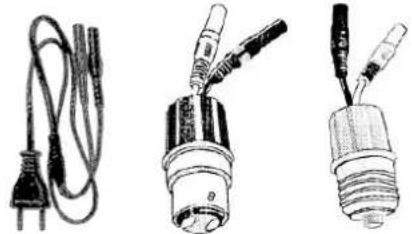
| Included accessories | Mains plug adapter, B22 socket adapter, E27 socket adapter |
| Installation category | CAT II (230 V) |
| Operating temperature | 0 °C to 40 °C |
| Operating humidity | < 80 % RH |
| Storage temperature | -10 °C to 45 °C |
| Maximum altitude | 2000 m |
| Cleaning and maintenance | Unplug and clean with a damp cloth and mild soap; dry before reuse |
| Safety | Double insulation, use on networks without excessive overvoltage |
| Warranty | 1 year against defects in materials or workmanship |
| Compliance | Low Voltage Directive 2006/95/EC and EMC Directive 2004/108/EC |
Frequently Asked Questions - CBF01 MULTIMETRIX
User questions about CBF01 MULTIMETRIX
0 question about this device. Answer the ones you know or ask your own.
Ask a new question about this device
Download the instructions for your Detector in PDF format for free! Find your manual CBF01 - MULTIMETRIX and take your electronic device back in hand. On this page are published all the documents necessary for the use of your device. CBF01 by MULTIMETRIX.
USER MANUAL CBF01 MULTIMETRIX
natural_image
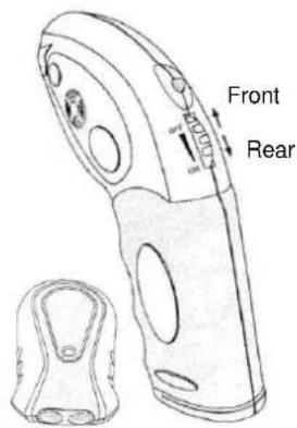
Technical line drawing of a handheld device with two views: one showing internal components and the other showing a handle mechanism (no text or symbols)natural_image
Three types of electrical probes with wires, shown from different angles (no text or symbols visible)natural_image
Line drawing showing two electrical cable connections: one with a plug and cable, the other with a hand holding a handheld device (no text or symbols)Fig.2
Fig.3
natural_image
Illustration of a hand holding a power tool inside an open electrical panel (no text or symbols visible)Fig.4
1. General instructions....12
1.1 Overview....12
1.2 Precautions for use 12
1.3 Symbols....13
2. Description....14
3. Functional description ....15
3.1 Fitting the receiver battery 15
3.2 Installing the emitter....15
3.3 Finding a circuit breaker or a fuse....16
3.4 Cleaning 18
3.5 Warranty 18
3.6 Maintenance....18
4. Technical specifications ....19
4.1 Emitter....19
4.2 Receiver....19
4.3 Compliance with European directives....19
4.4 Environment and storage conditions 19
CBF01
11
1. General instructions
1.1 Overview
You have purchased a circuit breaker finder (fuse, circuit breaker, contact breaker etc.) model CBF01 and we thank you for your custom.
The CBF01 is used to locate the protection and circuit-breaker for a mains outlet, a lamp or any other equipment or electric circuit powered by the mains network.
The appliance is composed of an emitter and a receiver. The emitter injects a signal onto the network, the same signal is then detected by the receiver. The receiver issues a sound signal and its green LED flashes when the signal is detected. The sensitivity of the receiver is adjustable in order to refine the exact location of the circuit breaker or the fuse for the tested circuit.
1.2 Precautions for use
- Respect the environment and storage conditions.
- This instrument is portable and autonomous and has been designed for
use: - indoors on 230 V CAT II networks
- in a level 2 pollution environment
- at an altitude below 2000 m
- at a temperature included between 5°C and 40°C and a relative humidity < 80 %.
- If the receiver LED lighting is low, or if the receiver is not operating normally you must replace the battery;
- Use adapted personal protection when dangerous live parts can be accessed on the installation on which the appliance is used.
- Before each use, check the good condition of the cable insulation and units. All elements of which the insulation is deteriorated (even partially) must be put out of service for repair or disposed of as waste.
1@BF01
Definition of installation categories according to excerpts from the IEC 61010-1, IEC 60364 and IEC 60664-1 standards:
CAT II: Power supply circuits for household appliances or equivalent appliances that can be subject to average transitory power surges.
Example: household appliances and portable electric tools
CAT III: Power supply circuits for appliances or equivalent appliances that can be subject to transitory power surges of a high value.
Example: power supply to industrial machines or appliances.
CAT IV: Circuits that can be subject to very high transitory power surges.
Example: power supply inputs.
1.3 Symbols


Danger hazard:
The operator undertakes to consult these instructions each time this danger hazard symbol is encountered.
9 V Battery
The CE marking certifies compliance with European directives.
Double or strengthened insulation
In the European Union, this product is the subject of selective waste sorting for the recycling of electric and electronic equipment in compliance with the Directive WEEE 2002/96/EC:
AC - Alternating current
Fuse
CBF01
2. Description
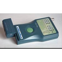
text_image
Front RearFig.1a: Emitter / Receiver
natural_image
Three types of electrical connectors and wires, including a power plug, coiled cable, and two bulbs with probes (no text or symbols visible)Fig. 1b: Connection accessories Connection adapter for mains outlet, B22 and E27 light bulb base.
1⊕BF01
3. Functional description
3.1 Fitting the receiver battery
Remove the cover from the battery housing by sliding it in the direction of the arrow. Fit a 9 V (6F22 or equivalent) battery in the housing taking care to respect the poles. Refit the cover.
3.2 Installing the emitter
Test of a wall mains outlet circuit:
- Connect both connectors on the mains cable adapter to the emitter unit.
- Connect the two pole plug to the mains wall outlet to be tested. Carry on at step 4. below.
Test of a lighting circuit:
- Power off the installation.
- After it has cooled, remove the light bulb from the circuit to be tested and replace it with an adapter with the same base. Connect both connectors on the adapter to the emitter unit.
- Power on the installation.
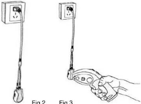
- The red LED on the emitter should turn on (fig. 2)
- Turn the receiver's rotating switch to the rear from the OFF position until it clicks. The green LED should turn on, detection sensitivity is at its maximum. If you continue turning the switch to the rear the sensitivity of the receiver will lessen gradually.
- Place the receiver by the emitter (fig. 3). The receiver will issue a sound signal and its green LED will flash.
- Power off the installation before disconnecting the adapter.
CBF01
15
The emitter-receiver unit is operational, you can now go on to the next step.
natural_image
Line drawing showing two electrical probes with labeled parts: one with a plug and cable, the other with a probe holding a remote control (no text or symbols present)Fig.2
Fig.3
3.3 Finding a circuit breaker or a fuse
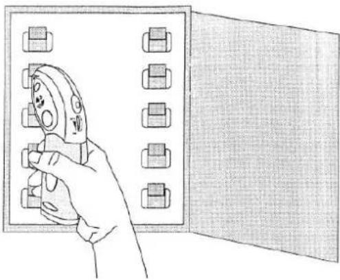
- Go to the distribution panel with the circuit-breakers and hold the receiver vertically by placing the flat surface of its tapered end directly on the circuit-breaker or the fuse (fig. 4).
Slowly move the receiver from the top to the bottom, and from left to right on the row of circuit breakers or fuses. The receiver will emit a sound signal and its green LED will flash when it detects the signal from the emitter.
If required, reduce the sensitivity of the receiver to locate the circuit breaker (or the fuse) that protects the circuits.
16BF01
natural_image
Illustration of a hand holding a power tool inside an open electrical cabinet (no text or symbols visible)Fig.4
-
After having located the circuit breaker (or the fuse), trip the circuit breaker (or remove the fuse). Repeat the detection with the receiver set to its maximum sensitivity for this circuit breaker (or fuse). If the receiver no longer detects a signal, the circuit breaker that you have tripped (or the fuse that you have removed) is the one that protects the circuit selected by the emitter. On the other hand, if the receiver can still detect the signal for the circuit breaker (or fuse), then this circuit breaker (or fuse) is not the one that protects the selected circuit.
-
Disconnect the emitter unit from the mains wall outlet or the light bulb base (and put back the light bulb)
-
Power back on by rearming the circuit breaker or refitting the fuse.
CBF01
17
3.4 Cleaning
Disconnect the cables for the external circuits and power off the appliance. Clean the instrument with a damp cloth and soap. Never use abrasive products or solvents.
Make sure the instrument is dry before reusing it.
3.5 Warranty
This equipment has a warranty for faulty manufacture or materials as per our sales terms and conditions.
During the warranty period (1 year), the instrument must only be repaired by the manufacturer, who reserves the right to either repair it or to totally or partially replace it.
If the equipment is returned to the manufacturer, the shipping costs will be paid by the customer.
The warranty will not apply in the event of:
-
inappropriate use of the equipment or use with incompatible equipment;
-
modifications made to the equipment without the explicit authorisation of the manufacturer's technical service;
-
work carried out on the appliance by a person not approved by the manufacturer;
-
an adaptation to a specific application which is not part of the definition of the equipment or in the operating instructions;
-
damage caused by shocks, falls or immersion.
3.6 Maintenance
Return the instrument to your distributor to have work carried out whether or not under the warranty.
If you must ship the instrument, preferably use its original packaging and indicate as clearly as possible the reasons for the return on a note enclosed with the shipment.
18BF01
4. Technical specifications
4.1 Emitter
- Input voltage: 200 \~ 240 V at 50 \~ 60 Hz
• Size: 80 x 50 x 31 mm
• Weight: approx. 55 g
4.2 Receiver
• Power supply: 9 V battery (6F22 or equivalent)
• Size: 186 x 90 x 38 mm
• Weight: approx. 150 g
4.3 Compliance with European directives
This appliance is compliant with the directive on low voltage 2006/95/EC and EMC 2004/108/EC.
4.4 Environment and storage conditions
Operating conditions: - temperature 0°C \~ 40°C - relative humidity < 80 %
Storage conditions: - temperature -10^ 45^ - relative humidity < 80%
CBF01
19
Inhaltsverzeichnis
natural_image
Three types of electrical connectors and wires, including a power plug, coiled cable, and two bulbous bulbs (no text or symbols visible)natural_image
Illustration of a hand using pliers to adjust or install components on an open electrical panel (no text or symbols)Abb. 4
natural_image
Three types of electrical connectors and wires, including a power plug, a bulb, and a light bulb (no text or symbols visible)natural_image
Line drawings of two electrical connectors: one with a power outlet, the other with a handheld device (no text or symbols)Fig.2
Fig.3
natural_image
Illustration of a hand holding a power tool inside an open electrical panel (no text or symbols visible)Fig.4
natural_image
Three types of electrical connectors and wires, including a power plug, coiled cable, and two bulbs with probes (no text or symbols visible)natural_image
Line drawings of two electrical connectors: one with a power outlet, the other with a handheld device (no text or symbols)Fig.2
Fig.3
natural_image
Illustration of a hand holding a pliers next to an open electrical panel (no text or symbols visible)Fig. 4
200 Foxborough Blvd. - Foxborough - MA 02035
Tel: (508) 698-2115 - Fax: (508) 698-2118