V10 - Air Conditioning HTW - Free user manual and instructions
Find the device manual for free V10 HTW in PDF.

| Product Type | VRF multi-split air conditioning (outdoor unit) |
| Brand | HTW |
| Model | V10 |
| Category | Air Conditioning |
| Refrigerant | R410A |
| Power Supply | Three-phase 380-415V ~ 50Hz |
| Power (HP) | From 8 to 32 HP depending on configuration |
| Maximum Current (MCA) | From 24 A (8HP) to 66.9 A (32HP) |
| Dimensions (H x W x D) | Varies by model; e.g., 1635 mm height for 8-12HP |
| Weight | Not specified in the manual, estimated between 100 and 300 kg depending on power |
| Maximum number of indoor units | Up to 64 units |
| Maximum piping length | 1000 m (total), 175 m (between farthest indoor unit and first distributor) |
| Maximum height difference | 90 m (outdoor above), 110 m (outdoor below) |
| Protections | High pressure, low pressure, overheating, phase reversal, etc. |
| Maintenance | Annual maintenance recommended by a professional |
| Safety | Mandatory grounding, omnipolar cut-off device, etc. |
| Standards | EN/IEC 61000-3-12, EN378 |
Frequently Asked Questions - V10 HTW
User questions about V10 HTW
0 question about this device. Answer the ones you know or ask your own.
Ask a new question about this device
Download the instructions for your Air Conditioning in PDF format for free! Find your manual V10 - HTW and take your electronic device back in hand. On this page are published all the documents necessary for the use of your device. V10 by HTW.
USER MANUAL V10 HTW
natural_image
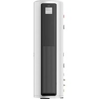
Exterior view of a white HTW air conditioning unit with blue branding and three heat management icons (no readable text beyond logos)OUTDOOR UNIT
V10
HTW-VO252FI13V10 / HTW-VO280FI16V10 / HTW-VO335FI20V10
HTW-VO400FI23V10 / HTW-VO450FI26V10 / HTW-VO500FI29V10
HTW-VO560FI33V10 / HTW-VO670FI39V10 / HTW-VO730FI43V10
HTW-VO785FI46V10 / HTW-VO850FI50V10 / HTW-VO900FI53V10
Please, read carefully before using the product.
HTW-VO252FI13V10 / HTW-VO280FI16V10 / HTW-VO335FI20V10
HTW-VO400FI23V10 / HTW-VO450FI26V10 / HTW-VO500FI29V10
HTW-VO560FI33V10 / HTW-VO670FI39V10 / HTW-VO730FI43V10
HTW-VO785FI46V10 / HTW-VO850FI50V10 / HTW-VO900FI53V10
NOTA
natural_image
Line drawing of three identical air conditioning units with cooling fans and ventilation grilles (no text or symbols)
Correct
Figure 4.4
natural_image
Line drawing of three air conditioning units with cooling fans and a bracket, labeled '× Incorrecto' (no other text or symbols)Figura 4.5
natural_image
Line drawing of three identical air conditioning units with cooling fans and ventilation grilles, mounted on a support base (no text or symbols)√ Correcto
Figura 4.6
natural_image
Line drawing of three industrial HVAC units with cooling fans and ventilation ducts (no text or symbols)× Incorrecto
Figura 4.7

Nota
flowchart
graph TD
    A["A"] -->|a| B["b"]
    B -->|c| C["C"]
Figura 5.2
natural_image
Technical line drawing of a mechanical assembly with pipes and housing (no text or symbols)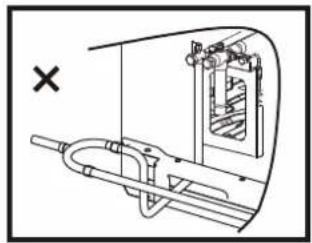
natural_image
Technical diagram of a mechanical assembly with no visible text or symbols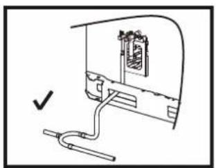
natural_image
Simple line drawing of a device with a cable and connector, no text or symbols present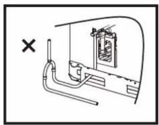
natural_image
Technical line drawing of a mechanical assembly with pipe and housing (no text or symbols)Figura 5.9
5.4.6 Soldadura
Figura 5.13
Figura 5.24
natural_image
Technical line drawing of a computer setup with internal components and a cable, no text or symbols presentFigura 5.28
natural_image
Technical line drawing of a mechanical assembly with bolts and wires (no text or symbols)Figura 5.30
natural_image
Technical line drawing of a mechanical assembly with bolts and tubing (no text or symbols)Figura 5.31
natural_image
Technical line drawing of a multi-panel rack or storage unit (no text or symbols)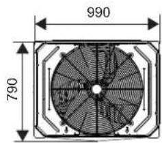
14\~16 HP

natural_image
Technical line drawing of a multi-panel storage unit or rack structure (no text or symbols)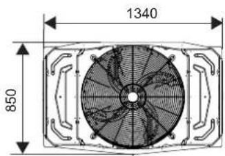
18\~22 HP
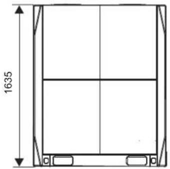
natural_image
Technical line drawing of a rectangular frame with vertical supports and a horizontal centerline, dimensioned as 1635 units (no text or symbols)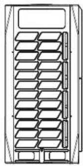
natural_image
Technical line drawing of a multi-tiered storage unit or rack (no text or symbols)
24\~32 HP
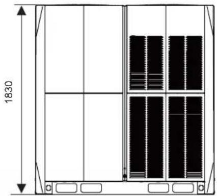
natural_image
Technical line drawing of a multi-panel storage unit with vertical dimensions and internal compartments (no text or symbols)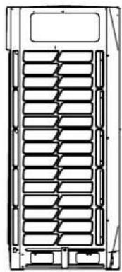
natural_image
Technical line drawing of a multi-layered mechanical component with no visible text or symbols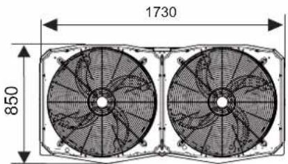
Leyenda:
Leyenda:
Leyenda:
natural_image
Technical line drawing of a mechanical component with internal channels and a dimension label (704), no readable text or symbols beyond the dimension marker.8 × ST3.9
Tornillos autorroscantes
HTW-VO252FI13V10 / HTW-VO280FI16V10 / HTW-VO335FI20V10
HTW-VO400FI23V10 / HTW-VO450FI26V10 / HTW-VO500FI29V10
HTW-VO560FI33V10 / HTW-VO670FI39V10 / HTW-VO730FI43V10
HTW-VO785FI46V10 / HTW-VO850FI50V10 / HTW-VO900FI53V10
Contents
- Overview 1
- About the Packing Box 2
- About the Outdoor Unit Combination .... 3
- Preparations Before Installation 5
- Outdoor Unit Installation....11
- Configuration 21
- Commissioning 25
- Maintenance and Repair 26
- Error codes ......27
- Disposal 27
- Technical Data 28
1 Overview
1.1 Meaning of Various Labels
The precautions and things to note in this document involve very important information. Please read them carefully.
- All the activities described in the installation manual must be performed by an authorized installation personnel.

Warning
A situation that may lead to severe injury or death.

Caution
A situation that may lead to mild or moderate injury.

Note
A situation that may cause damage to the equipment or loss of property.

Information
Indicates a useful hint or additional information.
1.2 What the Installation Operator Must Know
1.2.1 Overview
If you are uncertain on how to install or run the unit, please contact the agent.

Warning
- Make sure the installation, testing and materials used comply with the applicable law.
- Plastic bags should be disposed of properly. Avoid contact by children. Potential risk: Asphyxia.
- Do not touch the refrigerant piping, water piping or internal parts during operations, and when the operation has just been completed. This is because the temperature may be too high or too low. Let them recover to the normal temperature first. Wear protective gloves if you must come in contact with these.
- Do not touch any refrigerant that has accidentally leaked.

Caution
- Please wear the appropriate personal protective tools during installation, maintenance or repair of the system (protective gloves, safety glasses, etc.).
Do not touch the air inlet or aluminium fin of the unit.

Note
- The figure shown in this manual is for reference only and may be slightly different from the actual product.
- Improper installation or connection of equipment and accessories may cause electric shocks, short circuits, leaks, fires, or other damage to the equipment. Use only accessories, equipment and spare parts made or approved by manufacturer.
Take appropriate measures to prevent small animals from entering the unit. Contact between small animals and electrical components may cause system malfunction, leading to smoke or fire. - Do not place any object or equipment on top of the unit.
Do not sit, climb, or stand on the unit. - Operation of this equipment in a residential environment could cause radio interference.
1.2.2 Installation site
- Provide sufficient space around the unit for maintenance and air circulation.
- Make sure the installation site can bear the weight of the unit and vibrations.
• Make sure the area is well ventilated.
• Make sure the unit is stable and level.
Do not install the unit in the following locations:
- An environment where there is a potential risk of explosions.
- Where there are equipment emitting electromagnetic waves. Electromagnetic waves may disrupt the control system, and cause the unit to malfunction.
Where there are existing fire hazards like leakage of flammable gases, - carbon fibres, and combustible dust (such as diluents or gasoline).
Where corrosive gases (such as sulphurous gases) are produced. - Corrosion of copper pipes or welded parts may lead to refrigerant leakage.
1.2.3 Refrigerant

Warning
- During the test, do not exert a force greater than the maximum allowed pressure on the product (as shown on the nameplate).
- Take appropriate precautions to prevent refrigerant leakage. If the refrigerant gas leaks, ventilate the area immediately. Possible risk: An excessively high concentration of refrigerant in an enclosed area can lead to anoxia (oxygen deficiency). The refrigerant gas may produce a toxic gas if it comes in contact with fire.
- Refrigerant must be recovered. Do not release it to the environment. Use the vacuum pump to draw the refrigerant out from the unit.

Note
- Make sure the refrigerant piping is installed in accordance with the applicable law. In Europe, EN378 is the applicable standard.
- Make sure the piping and connections are not placed under pressure.
- After all the piping connections have been completed, check to make sure there is no gas leak. Use nitrogen to conduct the leak check for gas
- Do not charge refrigerant before the wiring layout is completed.
- Only charge the refrigerant after the leak tests and vacuum drying have been completed.
-
When charging the system with refrigerant, do not exceed the allowable charge to prevent liquid strike.
-
Do not charge more than the specified amount of refrigerant. This is to prevent the compressor from malfunctioning.
- The refrigerant type is clearly marked on the nameplate.
- The unit is charged with refrigerant when it is shipped from the factory. But depending on the piping dimensions and length, the system require additional refrigerant.
- Only use tools specific to the type of system refrigerant to make sure the system can withstand the pressure, and prevent foreign objects from entering the system.
- Follow the steps below to charge the liquid refrigerant:
Open the refrigerating cylinder slowly.
Charge the liquid refrigerant. Charging with gas refrigerant may hamper normal operations.

Caution
Once refrigerant charging is completed or suspended, close the refrigerant tank valve immediately. The refrigerant may volatilize if the refrigerant tank valve is not closed in time.
1.2.4 Electricity

Warning
- Make sure you switch off the power of the unit before you open the electric control box, and access any circuit wiring or components inside. At the same time, this prevents the unit from being accidentally powered up during installation or maintenance work.
- Once you open the cover of the electric control box, do not let any liquid spill into the box, and do not touch the components in the box with wet hands.
- Cut off power supply more than 5 minutes prior to access the electrical parts. Measure the voltage of the main circuit capacitor or electrical component terminals to make sure the voltage is less than 36V before you touch any circuit component. Refer to the connections and wiring on the nameplate for the master circuit terminals and connections.
- The installation must be completed by professionals, and must comply with local laws and regulations.
- Make sure the unit is grounded, and the grounding must conform to the local law.
- Use only copper core wires for installation.
- Wiring must be carried out in accordance with what is stated in the nameplate.
- The unit does not include a safety switch device. Make sure a safety switch device that can completely disconnect all polarities is included in the installation, and that the safety device can be completely disconnected when there is excessive voltage (such as during a lightning strike).
- Make sure the wiring ends are not subjected to any external force. Do not pull or squeeze the cables and wires. At the same time, make sure the wiring ends are not in contact with the piping or sharp edges of the sheet metal.
- Do not connect the earth wire to public pipes, telephone earth wires, surge absorbers and other places that are not designed for grounding. A gentle reminder that improper grounding may cause electric shock.
- Use a dedicated power supply cord for the unit. Do not share the same power source with other equipment.
- A fuse or circuit breaker must be installed, and these must conform to the local law.
- Make sure an electric leakage protection device is installed to prevent electric shocks or fire. The model specifications and characteristics (anti-high-frequency noise characteristics) of the electric leakage protection device are compatible with the unit to prevent frequent tripping.
- Make sure all terminals of the components are firmly connected before you close the cover of the electric control box. Before you power on and start the unit, check that the cover of the electric control box is tight and secured properly with screws. Once the box is covered, do not let any liquid spill into the electric control box, and do not touch the components in the box with wet hands.
- Make sure a lightning rod is installed if the unit is placed on the roof or other places that can be easily struck by lightning.
- The appliance shall be installed in accordance with national wiring regulations.
- If the supply cord is damaged, it must be replaced by the manufacturer or its service agent or a similarly qualified person in order to avoid a hazard
- An all-pole disconnection switch having a contact separation of at least 3mm in all poles should be connected in fixed wiring
- The dimensions of the space necessary for correct installation of the appliance including the minimum permissible distances to adjacent structures
- The temperature of refrigerant circuit will be high, please keep the interconnection cable away from the copper tube

Note
- Do not install the power cord near equipment that is susceptible to electromagnetic interference, such as TV, and radios to prevent interference.
- Use a dedicated power supply cord for the unit. Do not share the same power source with other equipment. A fuse or circuit breaker must be installed, and these must conform to the local law.

Information
The installation manual is only a general guide on the wiring and connections, and is not specifically designed to contain all information regarding this unit.
1.3 Important Information for User
- If you are uncertain on how to run the unit, please contact the installation personnel.
- This unit is not suitable for people who lack physical strength, cognitive sense or mental ability, or who lack experience and knowledge (including children). For their own safety, they should not use this unit unless they are supervised or guided by the respective personnel in charge of their safety. Children must be monitored to ensure that they do not play with this product.

Warning
To prevent electric shock or fire:
- Do not wash the electric box of the unit.
- Do not operate the unit with wet hands.
- Do not place any items that contain water on the unit.

Note
- Do not place any object or equipment on top of the unit.
- Do not sit, climb, or stand on the unit.
2 About the Packing Box
2.1 Overview
This chapter mainly introduces the subsequent operations after the outdoor unit has been delivered to site and unpacked.
This specifically includes the following information:
- Unbox and handling the outdoor unit.
• Take out the accessories of the outdoor unit. - Dismantle the transport rack.
Remember the following:
- At the time of delivery, check the unit for any damage. Report any damage immediately to the carrier's claim agent.
- As far as possible, transport the packaged unit to its final installation site to prevent damage during the handling process.
Take note of the following items when transporting the unit:

Fragile. Handle with care.

Keep the unit with its front facing upwards so as not to damage the compressor.
- Select the unit transportation path in advance.
NOTE
Taking into account the company's policy of continuous product improvement, both the aesthetics and dimensions, technical sheets and accessories of this equipment may change without prior notice.
ATTENTION
Read this manual carefully before installing and using your new unit. Be sure to keep this manual for future reference.
- As shown in the following figure, it is better to use a crane and two long belts to lift the unit. Handle the unit carefully to protect it, and note the position of the centre of gravity of the unit.
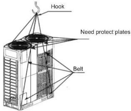

Note
- Use a leather belt that can adequately support the weight of the unit, and has a width ≤ 20 mm.
- Images are for reference only. Please refer to the actual product.
2.2 Unbox the Outdoor Unit
Take the unit out from the packing materials:
- Be careful not to damage the unit when you use a cutting tool to remove the wrapping film.
- Remove the four nuts on the wooden back stand.

Warning
Plastic film should be disposed of properly. Avoid contact by children. Potential risk: Asphyxia.
2.3 Taking Out Accessories of Outdoor Unit
- The accessories for the unit are stored in two parts. Documents like the manual are located at the top of the unit. Accessories like the pipes are located inside the unit, on top of the compressor. The accessories in the unit are as follows:
| Name | Qty Function | Outline | |
| Outdoor unit installation manual | 1 |  | — |
| Outdoor unit operation manual | 1 |  | — |
| Erp information | 1 | [KYYZ] | — |
| Information requirements for heat pumb | 1 | [W7ZA] | — |
| Screw pack | 1 |  | Reserved for maintenance |
| 90° socket elbow | 1 |  | To connect piping |
| Sealing cover | 8 |  | To clean pipes |
| L-shaped pipe connection | 2 | 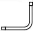 | To connect gas and liquid pipes |
| Build-out resistor | 2 | 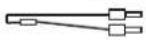 | To improve communication stability |
| Wrench | 1 | 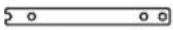 | To remove the side plate screws |
2.4 Pipe Fittings
- The schematic after the L-shaped pipe (from accessories) is properly connected to the unit is shown below:
8-22HP
24-32HP
Unit: mm
| SIZE\HP | 14-168-10 | 18-24 30-32 | 212 26-28 | |||
| A | 12.7 | 15.9 | 15.9 | 19.1 | 22.2 | 22.2 |
| B | 25.4 | 28.6 | 31.8 | 31.8 | 31.8 38.1 |
2.5 Remove the Protect board
Protecting boards are placed around the condenser, please remove the protecting boards when installing the unit; otherwise the capacity of the outdoor unit will be affected.
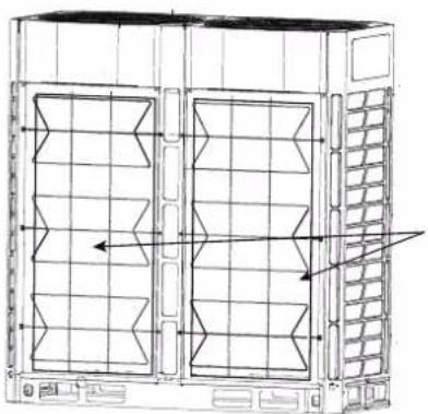
natural_image
Technical line drawing of a server rack unit with ventilation grilles and heat exchangers (no text or symbols)condenser protect board
3 About the Outdoor Unit Combination
3.1 Overview
This chapter contains the following information:
- List of branch joint fittings.
- Recommended combination for outdoor unit.
3.2 Branch joints
| Description | Model Name |
| Outdoor Unit Branch Joint Assembly | FQZHW-02N1E |
| FQZHW-03N1E | |
| Indoor Unit Branch Joint Assembly | FQZHN-01D |
| FQZHN-02D | |
| FQZHN-03D | |
| FQZHN-04D | |
| FQZHN-05D | |
| FQZHN-06D | |
| FQZHN-07D |
On the choice of branch joints, refer to section 4.3.3 on the selection of branch joints for refrigerant piping.
Recommended Outdoor Unit Combination3.3
| HP HP | 8 | 10 | 12 | 14 | 16 | 18 | 20 | 22 | 24 | 26 | 28 | 30 | 32 | Max Qty. of indoor units |
| 8 | ● | 13 | ||||||||||||
| 10 | ● | 16 | ||||||||||||
| 12 | ● | 20 | ||||||||||||
| 14 | ● | 23 | ||||||||||||
| 16 | ● | 26 | ||||||||||||
| 18 | ● | 29 | ||||||||||||
| 20 | ● | 33 | ||||||||||||
| 22 | ● | 36 | ||||||||||||
| 24 | ● | 39 | ||||||||||||
| 26 | ● | 43 | ||||||||||||
| 28 | ● | 46 | ||||||||||||
| 30 | ● | 50 | ||||||||||||
| 32 | ● | 53 | ||||||||||||
| 34 | ● | ● | 56 | |||||||||||
| 36 | ● | ● | 59 | |||||||||||
| 38 | ● | ● | 63 | |||||||||||
| 40 | ● | ● | 64 | |||||||||||
| 42 | ● | ● | 64 | |||||||||||
| 44 | ●● | 64 | ||||||||||||
| 46 | ● | ● | 64 | |||||||||||
| 48 | ● | ● | 64 | |||||||||||
| 50 | ● | ● | 64 | |||||||||||
| 52 | ●● | 64 | ||||||||||||
| 54 | ● | ● | 64 | |||||||||||
| 56 | ●● | 64 | ||||||||||||
| 58 | ● | ● | 64 | |||||||||||
| 60 | ● | ● | 64 | |||||||||||
| 62 | ● | ● | 64 | |||||||||||
| 64 | ●● | 64 | ||||||||||||
| 66 | ● | ● | ● | 64 | ||||||||||
| 68 | ● | ● | ● | 64 | ||||||||||
| 70 | ● | ● | ● | 64 | ||||||||||
| 72 | ● | ● | ● | 64 | ||||||||||
| 74 | ● | ● | ● | 64 | ||||||||||
| 76 | ●● | ● | 64 | |||||||||||
| 78 | ● | ● | ● | 64 | ||||||||||
| 80 | ● | ● | ● | 64 | ||||||||||
| 82 | ● | ● | ● | 64 | ||||||||||
| 84 | ●● | ● | 64 | |||||||||||
| 86 | ● | ● | ● | 64 | ||||||||||
| 88 | ●● | ● | 64 | |||||||||||
| 90 | ● | ● | ● | 64 | ||||||||||
| 92 | ● | ●● | 64 | |||||||||||
| 94 | ● | ●● | 64 | |||||||||||
| 96 | ●●● | 64 |

Caution
- In the system where all indoor units are running at the same time, the total capacity of the indoor units should be less than or equal to the combined capacity of the outdoor unit to prevent overloading in bad working conditions or narrow operating space.
- The total capacity of the indoor units can be up to a maximum of 130% of the combined capacity of the outdoor unit for a system where not all the indoor units are operating at the same time.
- If the system is applied in a cold region (ambient temperature is -10^ and below) or a very hot, heavy loading environment, the total capacity of the indoor units should be less than the combined capacity of the outdoor unit.
4 Preparations Before Installation
4.1 Overview
This chapter mainly describes the precautions and things to note before the unit is installed at the site.
This mainly includes the following information:
- Choose and Prepare the Installation Site
- Select and Prepare the Refrigerant Piping
- Select and Prepare the Electrical Wiring
4.2 Choose and Prepare the Installation Site
4.2.1 Site requirements for installation of outdoor unit
- Provide sufficient space around the unit for maintenance and air circulation.
- Make sure the installation site can bear the weight of the unit and vibrations.
- Make sure the area is well ventilated.
- Make sure the unit is stable and level.
- Choose a place where the rain can be avoided as much as possible.
- The unit should be installed in a location where the noise generated by the unit will not cause any inconveniences to any person.
- Choose a site that will comply with the applicable law.
Do not install the unit in the following locations:
- An environment where there is a potential risk of explosions.
- Where there are equipment emitting electromagnetic waves. Electromagnetic waves may disrupt the control system, and cause the unit to malfunction.
- Where there are existing fire hazards like leakage of flammable gases, carbon fibres, and combustible dust (such as diluents or gasoline).
- Where corrosive gases (such as sulphurous gases) are produced. Corrosion of copper pipes or welded parts may lead to refrigerant leakage.
- Where mineral oil mist, spray, or steam may exist in the atmosphere. Plastic parts may age, fall off or cause water leakage.
- Where there is a high salt content in the air such as places near the sea.

Caution
Electric appliances that should not be used by the general public must be installed in the safety area to prevent others from getting close to these electric appliances.
- Both indoor and outdoor units are suitable for the installation of commercial and light industrial environment.
- An excessively high concentration of refrigerant in an enclosed area can lead to anoxia (oxygen deficiency).

Note
- This is a class A product. This product may cause radio interference in the home environment. The user may need to take the necessary measures if such a situation does arise.
- The unit described in this manual may cause electronic noise generated by radio frequency energy. The unit conforms to the design specifications and provides reasonable protection to prevent such interference. However, there is no guarantee that there will be no interference during a specific installation process.
-
Therefore, it is suggested that you install the units and wires at an appropriate distance from devices like sound equipment and personal computers.
-
Do take into considerations adverse environmental conditions such as strong winds, typhoons or earthquakes as an improper installation may cause the unit to overturn.
Take precautions to make sure the water will not damage the installation space and environment in the event of a water leakage. - If the unit is installed in a small room, refer to section 4.2.3 "Safety measures to prevent refrigerant leak" to make sure the refrigerant concentration does not exceed the permissible safety limit when there is a refrigerant leak.
- Make sure the air inlet of the unit is not directed at the main wind direction. Incoming wind will disrupt the operations of the unit. If necessary, use a deflector as an air baffle.
- Add water discharge piping on the base so that the condensed water will not damage the unit, and prevent the accumulation of water to form pits when the works are in progress.
4.2.2 Site requirements for installation of outdoor unit in cold regions

Note
Snow protection facilities must be installed in areas with snowfall. Refer to the following figure, (malfunctions are more common when there is insufficient snow protection facilities). In order to protect the unit from accumulated snow, increase the height of the rack, and install a snow shield at the air inlets and outlets.
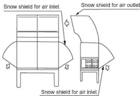
Figure 4.1

Note
Do not obstruct the air flow of the unit when you install the snow shield.
4.2.3 Safety measures to prevent refrigerant leak
Safety measures to prevent refrigerant leak
The installation personnel must make sure the safety measures to prevent leaks comply with local regulations or standards. If the local regulations do not apply, the following criteria can be applied.
The system uses R410A as the refrigerant. R410A itself is a completely non-toxic, and non-combustible refrigerant. However, do ensure that the air conditioning unit is installed in a room with sufficient space. This is so that when there is a serious leak in the system, the maximum concentration of the refrigerant gas in the room will not exceed the stipulated concentration, and is consistent with the relevant local regulations and standards.
About the maximum concentration level
The calculation for the maximum concentration of the refrigerant is directly related to the occupied space that the refrigerant may leak to and the charging amount of the refrigerant.
The measurement unit for concentration is kg/m ^3 (weight of gaseous refrigerant that has a volume of 1 m ^3 in the occupied space).
The highest level of permissible concentration must comply with the relevant local regulations and standards.
Based on the applicable European standards, the maximum permissible concentration level of R410A in the space occupied by humans is limited to 0.44 kg/m^3 .
4.3 Select and Prepare the Refrigerant Piping
4.3.1 Refrigerant piping requirements

Note
The R410A refrigerant pipeline system must be kept strictly clean, dry and sealed.
- Cleaning and drying: prevent foreign objects (including mineral oil or water) from mixing into the system.
- Seal: R410A does not contain fluorine, does not destroy the ozone layer, and does not deplete the ozone layer that protect the earth from harmful ultraviolet radiation. But if it is released, R410A can also cause a slight greenhouse effect. Therefore, you must pay special attention when you check the sealing quality of the installation.
-
The piping and other pressure vessels must comply with the applicable laws and suitable for use with the refrigerant. Use only phosphoric acid deoxidized seamless copper for the refrigerant piping.
-
Foreign objects in the pipes (including lubricant used during pipe bending) must be ≤ 30 mg/10m.
- Calculate all piping lengths and distances.
4.3.2 Allowable length and height difference for refrigerant piping
Refer to the following table and figure (for reference only) to determine the appropriate size.

Note
- The equivalent length of each branch joint is 0.5m.
- As much as possible, install the indoor units such that they are equidistant on both sides of the U-shape branch joint.
- When the outdoor unit is above the indoor unit, and the level difference exceeds 20m , it is recommended that an oil return bend be set up at every 10m interval on the gas pipe of the main piping. The recommended specifications of the oil return bend are as shown in figure 4.3.
- When the outdoor unit is below the indoor unit, and H ≥ 40 m, you need to increase the size of the liquid pipe in the main piping by one size.
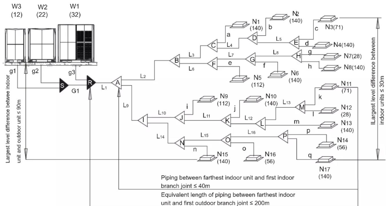
- The allowable length of the farthest indoor unit to the first branch joint in the system should be equal to or less than 40m unless specified conditions are met, in which case the permitted length is up to 90m. Please refer to requirement 2.
- Special-purpose branch joints from manufacturer for all branch joints should be used. Failing to do so may lead to severe system malfunction.
Table 4.1
| Permitted values | Piping | |||
| Piping lengths | Total piping length | ≤ 1000m | L_1 + 2 × _2 to L_16 + to q\ | |
| Piping between farthest indoor unit and first outdoor branch joint | Actual length | ≤ 175m | L_1 + _9 to L_13 + k (Refer to Requirement 1) | |
| Equivalent length | ≤ 200m | |||
| Piping between farthest indoor unit and first indoor branch joint | ≤ 40m / 90m | 9 to L13 + k (Refer to Requirement 2) | ||
| Piping between outdoor unit and outdoor branch joint | Actual length | ≤ 10 | g1+G1≤ 10m; g2+G1≤ 10m g3≤ 10m | |
| Level differences | Largest level difference between indoor unit and outdoor unit | Outdoor unit is above | ≤ 90m | (Refer to Requirement 3) |
| Outdoor unit is below | ≤ 110m | |||
| Largest level difference between indoor units | ≤ 30m | (Refer to Requirement 4) | ||
flowchart
graph TD
    subgraph "Largest level difference between indoor unit and outdoor unit ≤ 90m"
        W3["(W3, 12)"] --> g1["g1"]
        W2["(W2, 22)"] --> g2["g2"]
        W1["(W1, 32)"] --> g3["g3"]
        g1 --> S["S"]
        g2 --> S
        g3 --> R["R"]
        R --> L1["L1"]
        L1 --> A["A"]
        A --> L2["L2"]
        L2 --> B["B"]
        L2 --> F["F"]
        L2 --> G["G"]
        L2 --> H["H"]
        L2 --> N6["N6, 140"]
        L2 --> N5["N5, 112"]
        L2 --> F
        L2 --> e["e"]
        L2 --> F
        L2 --> F
        L2 --> F
    end

    subgraph "Piping between farthest indoor unit and first indoor branch joint ≤ 40m"
        W3 --> g1
        W2 --> g2
        W1 --> g3
    end

    subgraph "Equivalent length of piping between farthest indoor unit and first outdoor branch joint ≤ 200m"
        W3 --> g1
        W3 --> g2
        W3 --> g3
        W2 --> g1
        W2 --> g2
        W2 --> g3
        W1 --> g1
        W1 --> g2
        W1 --> g3
    end

    subgraph "ILargest level difference between indoor units ≤ 30m"
        W3 --> b["N1 (140)"]
        W3 --> d["E"]
        W3 --> h["h"]
        W3 --> k["k"]
        W3 --> M["M"]
        W3 --> p["p"]
        W3 --> q["q"]
        W3 --> N17["N17, 140"]

    subgraph "Piping between farthest indoor unit and first indoor branch joint ≤ 40m"
        W3 --> i["N9 (112)"]
        W3 --> j["L11"]
        W3 --> K["L12"]
        W3 --> L["L16"]
        W3 --> P["P"]
    end

    subgraph "Equivalent length of piping between farthest indoor unit and first outdoor branch joint ≤ 200m"
        W3 --> n["N15 (140)"]
        W3 --> o["N16 (56)"]
    end
Figure 4.2
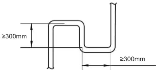
Figure 4.3
The piping length and level difference requirements that apply are summarized in Table 4.1 and are fully described as follows.
- Requirement 1: The piping between the farthest indoor unit (N11) and the first outdoor branch joint (R) should not exceed 175m (actual length) and 200m (equivalent length). (The equivalent length of each branch joint is 0.5m.)
- Requirement 2: The piping between the farthest indoor unit (N11) and first indoor branch joint (A) should not exceed 40m in length ( 9 to L13} + k ≤ 40m) unless the following conditions are met and the following measures are taken, in which case the permitted length is up to 90m.
Conditions:
a) Each indoor auxiliary pipe (from each indoor unit to its nearest branch joint) joint does not exceed 20 m in length (a to m each ≤ 20m).
b) The difference in length between {the piping from first indoor branch joint (A) to the farthest indoor unit (N11)} and {the piping from the first indoor branch joint (A) to the nearest indoor unit (N1)} does not exceed 40m. That is: (9 to L13 + k) - (2 to L3 + a) ≤ 40m .
Measures:
a) Increase the diameter of the indoor main pipes (the piping between the first indoor branch joint and all other indoor branch joints, L2 to L16) as follows, except for indoor main pipes which are already the same size as the main pipe (L1), for which no diameter increases are required.
| φ9.5→φ12.7 | φ12.7→φ15.9 | φ15.9→φ19.1 |
| φ19.1→φ22.2 | φ22.2→φ25.4 | φ25.4→φ28.6 |
| φ28.6→φ31.8 | φ31.8→φ38.1 | φ38.1→φ41.3 |
| φ41.3→φ44.5 | φ44.5→φ54.0 |
3 Requirement 3: The largest level difference between indoor unit and outdoor unit should not exceed 90m (if the outdoor unit is above) or 110m (if the outdoor unit is below). Additionally: (i) If the outdoor unit is above and the level difference is greater than 20m, it is recommended that an oil return bend with dimensions as specified in Figure 4.3 is set every 10m in the gas pipe of the main pipe; and (ii) if the outdoor unit is below and the level difference is more than 40m, the liquid pipe of the main pipe (L1) should be increased one size.
4 Requirement 4: The largest level difference between indoor units should not exceed 30m.
4.3.3 Piping diameter
Table 4.2
| Piping Name | Model |
| Main piping | L1 |
| indoor main piping | L2, L3, L4, L5,... L16 |
| piping of indoor unit | a, b, c, d,... q |
| Indoor Unit Branch Joint Assembly | A, B, C, D, ... P |
| Outdoor Unit Branch Joint Assembly | S, R |
| Connection piping of outdoor unit | g1, g2, g3, G1 |
1) Select the branch joint diameters for the indoor unit
Based on the total capacity of the indoor unit, select the branch joint for the indoor unit from the following table.
Table 4.3
| Total capacity of indoor units A (×100W) | Gas side (mm) | Liquid side (mm) | Branch joint |
| A<168 | Φ15.9 | Φ9.53 | FQZHN-01D |
| 168≤A<224 | Φ19.1 | Φ9.53 | FQZHN-01D |
| 224≤A<330 | Φ22.2 | Φ9.53 | FQZHN-02D |
| 330≤A<470 | Φ28.6 | Φ12.7 | FQZHN-03D |
| 470≤A<710 | Φ28.6 | Φ15.9 | FQZHN-03D |
| 710≤A<1040 | Φ31.8 | Φ19.1 | FQZHN-03D |
| 1040≤A<1540 | Φ38.1 | Φ19.1 | FQZHN-04D |
| 1540≤A<1800 | Φ41.3 | Φ19.1 | FQZHN-05D |
| 1800≤A<2450 | Φ44.5 | Φ22.2 FQZHN-05D | |
| 2450≤A<2690 | Φ54.0 | Φ25.4 FQZHN-06D | |
| 2690≤A | Φ54.0 Φ28 | 6 FQZHN-07D |
2) Select the diameter of the main piping
- The main pipe (L1) and first indoor branch joint (A) should be sized according to whichever of Table 4.3, 4.4 and 4.5 indicates the larger size.
Table 4.4
| HP of ODU | Equivalent length of all liquid piping < 90 m | ||
| Gas side (mm) | Liquid side (mm) | The first indoor branch joint | |
| 8HP | 19.1 | 9.53 | FQZHN-02D |
| 10HP | 22.2 | 9.53 | FQZHN-02D |
| 12~14HP | 25.4 | 12.7 | FQZHN-02D |
| 16HP | 28.6 | 12.7 | FQZHN-03D |
| 18~24HP | 28.6 | 15.9 | FQZHN-03D |
| 26~34HP | 31.8 | 19.1 | FQZHN-03D |
| 36~54HP | 38.1 | 19.1 | FQZHN-04D |
| 56~66HP | 41.3 | 19.1 | FQZHN-05D |
| 68~82HP | 44.5 | 22.2 | FQZHN-05D |
| 84~96HP | 50.8 | 25.4 | FQZHN-05D |
Table 4.5
| Model | Equivalent length of all liquid piping ≥ 90 m | ||
| Gas side (mm) | Liquid side (mm) | First branch joint of the indoor unit | |
| 8HP | 22.2 | 12.7 | FQZHN-02D |
| 10HP | 25.4 | 12.7 | FQZHN-02D |
| 12~14HP | 28.6 | 15.9 | FQZHN-03D |
| 16HP | 31.8 | 15.9 | FQZHN-03D |
| 18~24HP | 31.8 | 19.1 | FQZHN-03D |
| 26~34HP | 38.1 | 22.2 | FQZHN-04D |
| 36~54HP | 41.3 | 22.2 | FQZHN-04D |
| 56~66HP | 44.5 | 22.2 | FQZHN-05D |
| 68~82HP | 54.0 | 25.4 | FQZHN-06D |
| 84~96HP | QZHNΦ67D | 28.6 | |
The pipe thickness of the refrigerant piping shall comply with the applicable legislation.
The minimal pipe thickness for R410A piping must be in accordance with the table below.
Table 4.6
| Piping outer diameter (mm) | Minimum thickness (mm) | Temper grade |
| ø6.4 | 0.80 | M-type |
| ø9.5 | 0.80 | |
| ø12.7 | 1.00 | |
| ø15.9 | 1.00 | |
| ø19.1 | 1.00 | |
| ø22.2 | 1.00 | Y2-type |
| ø25.4 | 1.00 | |
| ø28.6 | 1.00 | |
| ø31.8 | 1.25 | |
| ø34.9 | 1.25 | |
| ø38.1 | 1.50 | |
| ø41.3 | 1.50 | |
| ø44.5 | 1.50 | |
| ø50.8 | 1.80 | |
| ø54.0 | 1.80 |
Material: Only seamless phosphorus-deoxidized copper piping that complies with all applicable legislation should be used.
Thicknesses: Temper grades and minimum thicknesses for different diameters of piping should comply with local regulations.
Design pressure of R410 refrigerant is 4.4MPa (44bar).
Example: A system consisting of three outdoor units (32HP + 22HP + 12HP). The system's equivalent total liquid piping length is in excess of 90m. Refer to Table 4.5, main pipe L1 is 44.5/ 22.2. The total capacity index of all indoor units is 1794, refer to Table 4.3, main pipe L1 is 41.3/ 19.1. Main pipe L1 is the larger of 44.5/ 22.2 and 41.3/ 19.1, hence 44.5/ 22.2.
- If the required pipe size is not available, you can use other diameters by considering the following factors:
- In case the standard size is not available in local market, one size up pipe should be used.
-
In some conditions, the pipe size needs to be one size up than the standard size that is the "Size up Size" (for example: when the equivalent length of all the liquid piping is larger than 90m, the pipe size needs to be one size up; when the piping length from the farthest indoor unit to the first indoor unit is more than 40m, the indoor main pipe size needs to be one size up to allow the piping length up to 90m). In case the "Size up Size" is not available in the local market, the standard size pipe must be used.
-
Pipe sizes bigger than corresponding "Size up Size" cannot be used under any circumstances.
- Calculation for the additional refrigerant must be adjusted according to section 5.9 on the determination of the additional refrigerant volume.
3) Select the branch joint diameters for the outdoor unit
Select the branch joint of the outdoor unit from the table below.
Table 4.7
| Outdoor unit Qty. | Illustration |
| 2 units | 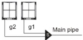 |
| 3 units | 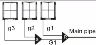 |
Table 4.8
| Outdoor unit Qty. | Outdoor connection pipes diameter | Outdoor branch joint kits |
| 2 units | g1, g2:8~12HP: Φ25.4/Φ12.7;14~22HP: Φ31.8/Φ15.924-32HP:38.1/19.1 | R:FQZHW-02N1E |
| 3 units | g1, g2,g3:8~12HP: Φ25.4/Φ12.7;14~22HP: Φ31.8/Φ15.9;24-32HP:38.1/19.1G1: Φ41.3/Φ22.2 | R+S:FQZHW-03N1E |

Note
- For systems with multiple units, the branch joints of the outdoor unit are sold separately.
4) indoor main piping
Table 4.9
| Indoor unit capacity A(×100W) | Pipe length ≤ 10m Pipe length > 10 m | |||
| Gas side (mm) | Liquid side (mm) | Gas side (mm) | Liquid side (mm) | |
| A≤45 | Φ12.7 Φ6.4 | Φ15.9 Φ9.53 | ||
| A≥56 | Φ15.9 Φ9.53 Φ19.1 | Φ12.7 | ||
5) An Example of Refrigerant Piping Selection
The example below illustrates the piping selection procedure for a system consisting of three outdoor units (32HP + 22HP + 12HP) and 17 indoor units, asa shown in Figure 4.2. The system's equivalent length of all liquid pipes is in excess of 90m; the piping between the farthest indoor unit and the first indoor branch joint is less than 40m in length; and each indoor auxiliary pipe (from each indoor unit to its nearest branch joint) is less than 10m in length.
- Select indoor main piping
Refer to Table 4.10 to select indoor auxiliary pipes (a-q)
- Select indoor main pipes and indoor branch joints B to P The indoor units (N3 and N4) downstream of indoor branch joint E have total capacity of 14 + 7.1 = 21.1kW. Refer to Table 4.3. Indoor main pipe L5 is 19.1 / 9.53. Indoor branch joint E is FQZHN-01D.
- The indoor units (N1 to N8) downstream of indoor branch joint B have total capacity of 14 × 5 + 11.2 + 7.1 + 2.8 = 91.1kW . Refer to Table 4.3. Indoor main pipe L2 is 31.8 / 19.1 . Indoor branch joint B is FQZHN-03D.
- The other indoor main pipes and indoor branch joints are selected in the same fashion.
- Select main pipe and indoor branch joint A The indoor units (N1 to N17) downstream of indoor branch joint A have total capacity of 14 × 9 + 11.2 × 2 + 7.1 × 2 + 5.6 × 2 + 2.8 × 2 = 179.4kW . The system's equivalent length of all liquid pipes is in excess of 90m. The total capacity of the outdoor units is 32 + 22 + 12 = 66HP . Refer to Table 4.3 and 4.5. Main pipe L1 is the larger of 41.3 / 19.1 and 44.5 / 22.2 , hence 44.5 / 22.2 . Indoor branch joint A is FQZHN-05D.
- Select outdoor connection pipes and outdoor branch joints The master unit is 32HP and the slave units are 22HP and 12HP. Refer to Table 4.9. Outdoor connection pipes g1 is 25.4 / 12.7 , g2 is 31.8 / 15.9 and g3 is 38.1 / 19.1 . Outdoor connection pipe G1 is 41.3 / 22.2 . There are three outdoor units in the system. Refer to Table 4.8. Outdoor branch joints S and R are FQZHW-03N1E.
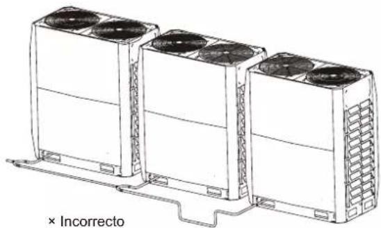
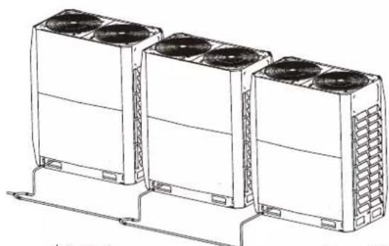
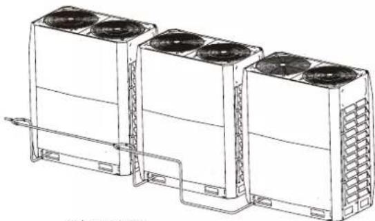
4.3.4 Arrangement and Layout of Multiple Outdoor Units
- The piping between the outdoor units must be level or slightly upwards.
- The piping connecting the outdoor units should be horizontal and must not be higher than the refrigerant outlets. If necessary, to avoid obstacles the piping may be vertically offset below the outlets. When inserting a vertical offset to avoid an obstacle, the whole outdoor piping should be offset, rather than just the section adjacent to the obstacle.
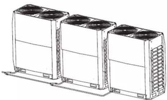
natural_image
Line drawing of three identical air conditioning units with cooling fans and heat sinks (no text or symbols)√ Correct
Figure 4.4
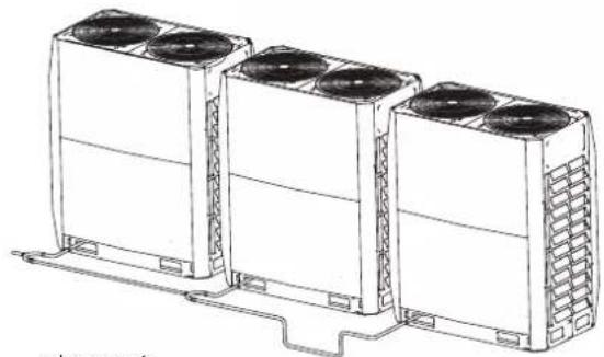
natural_image
Line drawing of three identical air conditioning units with cooling fans and heat sinks, mounted on a support base (no text or symbols)× Incorrect
Figure 4.5
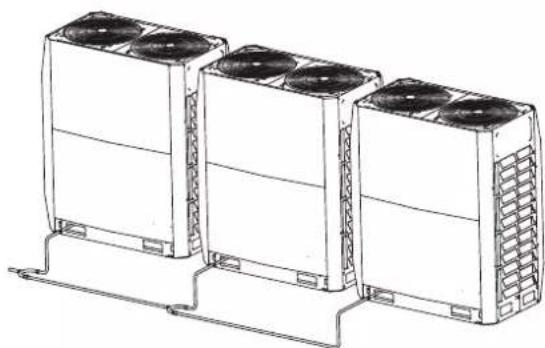
natural_image
Line drawing of three identical air conditioning units with cooling fans and ventilation grilles, mounted on a support base (no text or symbols)√ Correct
Figure 4.6
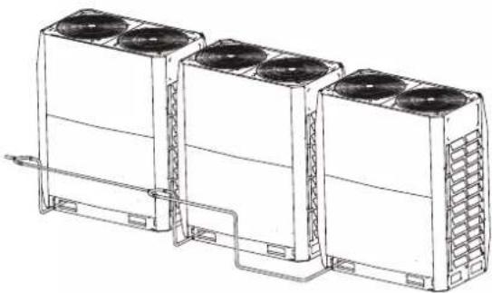
natural_image
Line drawing of three large industrial cooling units with fans and cooling fins, connected by piping (no text or symbols)× Incorrect
Figure 4.7

Note
- In systems with multiple outdoor units, the units should be placed in order from largest capacity unit to smallest capacity unit. The largest capacity unit must be placed on the first branch, and be set as the master unit, while the others should be set as slave units. The capacity of outdoor units A, B and C must meet the following conditions: A ≥ B ≥ C .
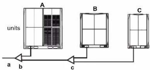
flowchart
graph TD
    A["units A"] -->|a| B["Units B"]
    A -->|b| C["Units C"]
    A -->|c| D["Units C"]
    B --> E["End"]
a To indoor unit
b Outdoor branch joint assembly (first branch joint)
c Outdoor branch joint assembly (second branch joint)
4.4 Select and Prepare the Electrical Wiring
4.4.1 Electrical compliance
This equipment conforms to:
EN/IEC 61000-3-12 specifications which states that the short circuit capacity (of the power supply), Ssc, is greater than or equal to the minimum Ssc value of the interface point between the user's power supply and the public system.
The installation personnel or users have the responsibility to consult the distribution network operators when necessary to ensure that the equipment only connects to a power supply with short circuit capacity, Ssc, greater than or equal to the minimum Ssc value.
Table 4.10
| Minimum Ssc value(kW) | |
| 8HP | 5820 |
| 10HP | 6110 |
| 12HP | 6401 |
| 14HP | 8026 |
| 16HP | 8026 |
Note: The European/international technical standards specified a harmonic current limit for devices connected to a public low-voltage system where the input current of each phase >16A and ≤ 75A .
the national wiring regulation.
- Maximum allowable voltage range variation between phases is 2%.
- Select circuit breaker that having a contact separation in all poles not less than 3 mm providing full disconnection, where MFA is used to select the current circuit breakers and residual current operation breakers:
Table 4.11
| Rated current of appliance (A) | Nominal cross-sectional area ( mm^2 ) | |
| Flexible cords | Cable for fixed wiring | |
| ≤3 | 0.5 and 0.75 | 1 to 2.5 |
| >3 and ≤6 | 0.75 and 1 | 1 to 2.5 |
| >6 and ≤10 | 1 and 1.5 | 1 to 2.5 |
| >10 and ≤16 | 1.5 and 2.5 | 1.5 to 4 |
| >16 and ≤25 | 2.5 and 4 | 2.5 to 6 |
| >25 and ≤32 | 4 and 6 | 4 to 10 |
| >32 and ≤50 | 6 and 10 | 6 to 16 |
| >50 and ≤63 | 10 and 16 | 10 to 25 |
4.4.2 Safety device requirements
- Select the wire diameters( minimum value) individually for each unit based on the table 4.11 and table 4.12, where the rated current in table 4.11 means MCA in table 4.12. In case the MCA exceeds 63A, the wire diameters should be selected according to
Table 4.12
| System | Outdoor Unit Power Current Compressor OFM | ||||||||||
| Voltage (V) | Hz M | In. (V) | Max. (V) | MCA (A) | TOCA (A) | MFA (A) | MSC (A) | RLA (A) | KW FLA | (A) | |
| 8HP | 380-415 | 50 | 342 | 440 | 24 | 30.9 | 32 | - | 10 | 0.56 | 6.3 |
| 10HP | 50 | 440 32 | 320.2 | 35.942 | - | 10.6 | 0.56 | 6.3 | |||
| 12HP | 50 | 440 32380 | 426.8 | 42.5 | - | 15.4 | 0.56 | 6.9 | |||
| 14HP | 50 | 342 | 440 | 33.1 | 40.3 | 40380 | 415 - | 25.8 | 0.92 | 7.3 | |
| 16HP | 50 | 440 40 | 388.4 | 45.342 | - | 25.8 | 0.92 | 7.3 | |||
| 18HP | 50 | 440 50 | 380.8 | 45.342 | - | 14+13 | 0.56+0.56 | 10.1 | |||
| 20HP | 50 | 440 50 | 388.8 | 45.342 | - | 17+16 0.56 | 0.56+0.56 | 10.9 | |||
| 22HP | 50 | 440 63 | 387.9 | 45.342 | - | 19+18 0.56 | 0.56+0.56 | 10.9 | |||
| 24HP | 50 | 440 63 | 388.4 | 415 342.3 | - | 17.4+16.6 | 0.92+0.92 | 13.1 | |||
| 26HP | 380-415 | 50 | 342 | 440 | 52.9 | 62.3 | 63 | - | 20+19.8 | 0.92+0.92 | 13.1 |
| 28HP | 380-415 | 50 | 342 | 440 | 58.7 | 64.1 | 63 | - | 22+21.8 | 0.92+0.92 | 14.9 |
| 30HP | 50 | 440 80 | 380.9 | 75.542 | - | 20+30 | 0.92+0.92 | 14.9 | |||
| 32HP | 50 | 440 80 | 380.9 | 75.542 | - | 22+30 | 0.92+0.92 | 14.9 | |||
i Information
Phase and frequency of power supply system: 3N\~50 Hz
Voltage: 380-415 V
5 Outdoor Unit Installation
5.1 Overview
This chapter includes the following information:
- Open the unit
- Outdoor unit installation
- Welding refrigerant piping
- Refrigerant piping check
- Refrigerant charging
- Power on the unit
5.2 Open the Unit
5.2.1 Open the outdoor unit
To enter the unit, you need to open the front panel, as shown below:
- For 8-22HP, first dismantle the front left and right columns. For 24-32HP, first dismantle the front left, middle, and right columns, where buckles are included in all 3 columns. Remove the screws, rotate and shift upwards by about 2 mm to remove left and right columns. Shift the middle column upwards by about 8 mm to take it out.
- Dismantle upper panel: Each upper panel has 4 screws (8-22HP) or 6 screws (24-32HP). After dismantling, lift it up by about 3 mm to take it out.
Dismantle lower panel: Each lower panel has 4 screws (8-22HP) or 6 screws (24-32HP) and 2 hooks. After dismantling, lift it up by about 3 mm to take it out.
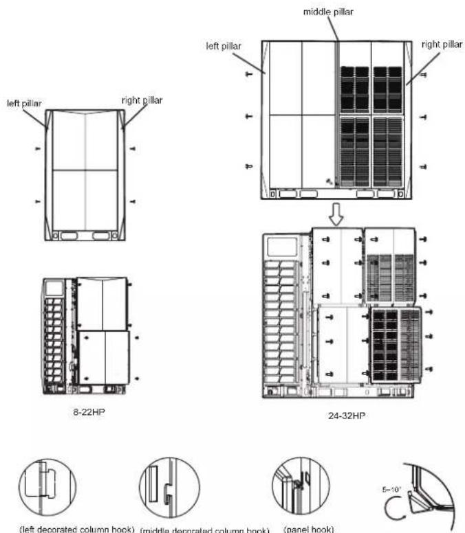
Figure 5.1
Open the electric control box of outdoor unit5.2.2
Once the front panel is opened, you can access the electric control box. Refer to section 5.2.2 on how to open the electric component box of the outdoor unit.
- Remove the cover of electric control box: (1) Loosen the two screws (by turning counter-clockwise for 1 to 3 turns) from the cover of the electric control box; (2) lift the cover upwards for 7 to 8mm , and then turn it outwards for 10 to 20mm ; (3) slide down the cover to remove it.
- Open and rotate the middle partition plate: (1) Loosen the two screws (by turning counter-clockwise for 1 to 3 turns) from the middle partition plate; (2) lift the partition plate upwards for 4 to 6mm , and then turn it outwards to open the partition plate; (3) slide the hinge (which can slide up and down along a sliding slot) at the bottom of the partition plate to the uppermost position to rotate the partition plate completely.

Note
Do not open the cover of electric control box until the preparing of wiring is OK.
The middle partition plate is used for maintaining. Do not open it when installation
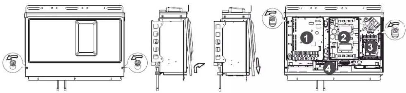
Figure 5.2
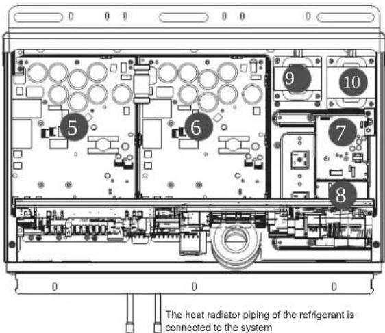
Figure 5.3
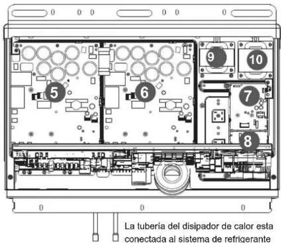
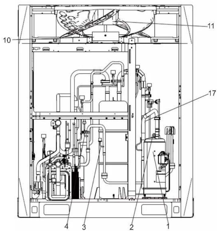
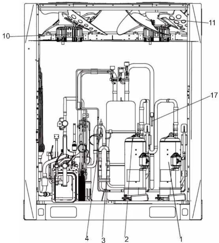
(1) Main board
(2) AC filter board
(3) Terminal block
(4) Comm. board
(5) Compressor drive board
(6) Compressor drive board
(7) DC fan drive board
(8) DC fan drive board
(9) Reactance
(10) Reatance
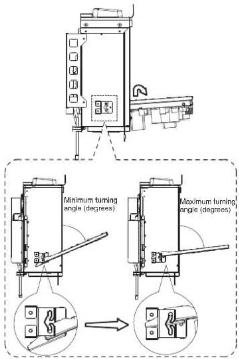
Figure 5.4

Caution
- Make sure the power supply is off before you carry out any electric control installation and maintenance work.
- To remove the entire electric control box, first discharge the refrigerant from the system, disconnect the pipe connecting the refrigerant radiator at the bottom of the electric control box. At the same time, remove all wiring connecting the electric control box and the internal components of the air conditioner.
- The images shown here are for illustrative purposes only and may differ from the actual product due to reasons like model and product upgrade. Please refer to the actual product.
5.3 Outdoor Unit Installation
5.3.1 Prepare structure for installation
Make sure the base where the unit is installed is strong enough to prevent vibrations and noise.
- When there is a need to increase the installation height of the unit, it is recommended that you use the installation structure shown in the following figure. Use a rack to support the four corners of the unit where necessary.
- The unit must be installed on a solid longitudinal base (steel beam frame or concrete). Make sure the base below the unit is larger than the area shaded in grey.
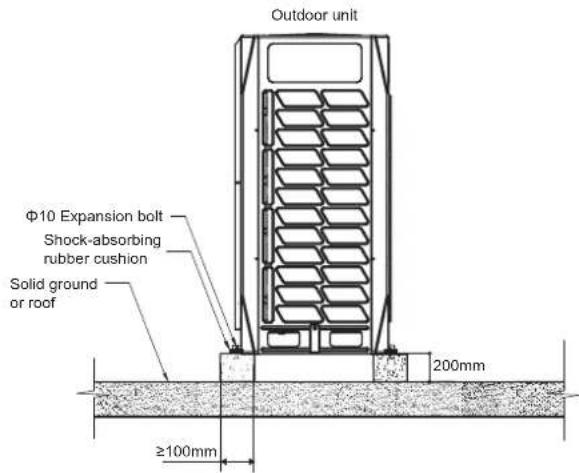
Figure 5.5
Expansion bolt positioning (Unit: mm)
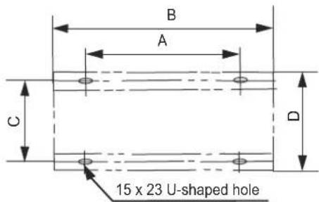
Figure 5.6
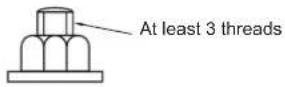
- Use four ground bolts, M12, to secure the unit in place. Best is to screw in the ground bolt until it is embedded in the base surface by at least 3 threads.

Note
- The base of the outdoor unit must use the solid concrete surface as the cement base or the steel beam frame base.
- The base must be completely level to ensure that every point of contact is even.
- During installation, make sure the base supports the vertical folds of the front and back under plates of the chassis directly as the vertical folds of the front and back under plates are Unit where the actual support for the unit load is.
- No gravel layer is required when the base is built on the roof surface, but the sand and cement on the concrete surface must be level, and the base should be chamfered along the edge.
- A water drainage ditch should be set around the base to drain the water around the equipment. Potential risk: slip.
- Check the load-bearing capacity of the roof to make sure it can support the load.
- When you choose to install the piping from the bottom, the base height should be above 200 mm.
Unit: mmTable 5.1
| SIZE\HP | 8,10, 12 14 | 16,18, 20, 22 24,26 | 28, 30, 32 |
| A | 740 | 1090 | 1480 |
| B | 990 | 1340 | 1730 |
| C | 723 | 723 | 723 |
| D | 790 | 790 | 790 |
5.4 Pipe Welding
5.4.1 Things to note when connecting the refrigerant piping

Caution
- During the test, do not exert a force greater than the maximum allowed pressure on the product (as shown on the nameplate).
- Take appropriate precautions to prevent refrigerant leakage. Ventilate the area immediately if the refrigerant leaks. Possible risk (An excessively high concentration of refrigerant in an enclosed area can lead to anoxia (oxygen deficiency); the refrigerant gas may produce a toxic gas if it comes in contact with fire.)
- Refrigerant must be recovered. Do not release it to the environment. Use professional fluorine extraction equipment to extract the refrigerant from the unit.

Note
- Make sure the refrigerant piping is installed in accordance with the applicable law.
- Make sure the piping and connections are not placed under pressure.
- After all the piping connections have been completed, check to make sure there is no gas leak. Use nitrogen to conduct the leak check for gas.
5.4.2 Connect refrigerant piping
Before the refrigerant piping is connected, make sure both the indoor and outdoor units are installed properly.
Connecting refrigerant piping includes:
- Connect refrigerant piping to outdoor unit
- Connect refrigerant piping to indoor unit (refer to the installation manual of the indoor unit)
- Connecting VRF piping assembly
- Assembly for connecting refrigerant piping branch joint
- Bear in mind the following guidelines:
- Braze
- Stop valve is used correctly
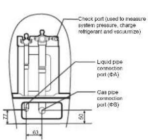
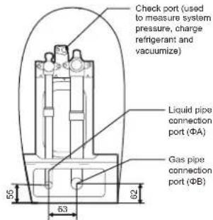
5.4.3 Outdoor refrigerant connecting pipe position
The outdoor refrigerant connecting pipe position is shown in the following figure.
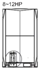
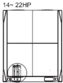
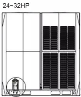
Figure 5.7
5.4.4 Connecting refrigerant piping to outdoor unit

Note
- Note the precautions when connecting the field piping for the refrigerant. Add brazing material.
- Use the attached piping fittings when working on the pipeline engineering on site.
- After installation, make sure the piping does not come in contact with each other, or the chassis.
The fittings provided as accessories can be used to complete the connection from the stop valve to the field piping
5.4.5 Connecting VRF piping assembly

Caution
- The wrong installation will cause the unit to malfunction.
The branch joints should be as level as possible, and the angular error does not exceed 10^ .
U type branch joint
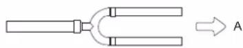
A-direction view
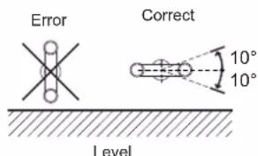
Figure 5.8
When there are multiple outdoor units, the branch joints must not be higher than the refrigerant piping as shown below:
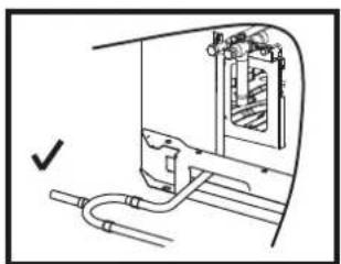
natural_image
Technical line drawing of a mechanical assembly with pipes and housing (no text or symbols)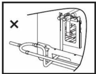
natural_image
Technical line drawing of a mechanical assembly with no visible text or symbols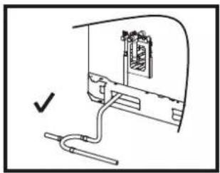
natural_image
Diagram of a mechanical assembly with a bracket and pipe connection (no text or symbols)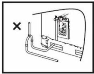
natural_image
Diagram of a mechanical or electrical component with pipes and a central chamber, marked with an 'X' symbol (no text or labels present)Figure 5.9
5.4.6 Brazing
- During brazing, use nitrogen as protection to prevent the formation of a large amount of oxide film in the pipes. This oxide film will have adverse effects on the valves and compressors in the cooling system, and may hamper normal operations.
- Use the reducing valve to set the nitrogen pressure to 0.02\~0.03 Mpa (a pressure that can be felt by the skin).
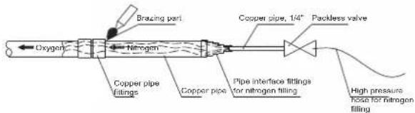
Figure 5.10
- Do not use antioxidants when brazing the pipe joints.
- Use copper-phosphorus alloys (BCuP) when brazing copper and copper, and no flux is required. When brazing copper and other alloy, flux is required.
Flux produces an extremely harmful effect on the refrigerant piping system. For example, using a chlorine-based flux is used may corrode the pipes, and when the flux contains fluorine, it will degrade the frozen oil.
5.4.7 Connect stop valves
The stop valve
- The following figure shows the names of all parts required for the installation of the stop valves.
- Stop valves are closed when unit is shipped from the factory.
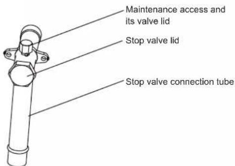
Figure 5.11
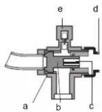
a Sealing component
b Axis
c Hexagonal hole
d Stop valve lid
e Maintenance access
Figure 5.12
Using of stop valve
- Remove the stop valve lid.
- Insert the hex wrench into the stop valve, and rotate the stop valve counter-clockwise.
- Stop turning when the stop valve cannot be rotated further.
Result: Valve is now open.
The fastening torque of the stop value is shown in table 5.2. Insufficient torque may cause the refrigerant to leak.
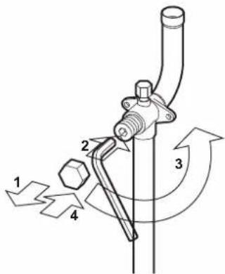
Figure 5.13
Close stop valve
- Remove the stop valve lid.
- Insert the hex wrench into the stop valve, and rotate the stop valve clockwise.
- Stop turning when the stop valve cannot be rotated further.
Result: Valve is now closed.
Direction to close:
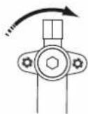
Figure 5.14
Table 5.2 Fastening torque
| Stop valve size (mm) | Tightening torque/N.m (turn clockwise to close) |
| Axis | |
| Valve body | |
| ∅12.7 | 9~30 |
| ∅19.1 | 12~30 |
| ∅22.2 | 16~30 |
| ∅25.4 | 24~30 |
| ∅28.6 | |
| ∅31.8 | 25.0~35 |
| ∅35.0 |
5.5 Pipe Flushing
To remove dust, other particles and moisture, which could cause compressor malfunction if not flushed out before the system is run, the refrigerant piping should be flushed using nitrogen. Pipe flushing should be performed once the piping connections have been completed with the exception of the final connections to the indoor units. That is, flushing should be performed once the outdoor units have been connected but before the indoor units are connected.

Caution
- Only use nitrogen for flushing. Using carbon dioxide risks leaving condensation in the piping. Oxygen, air, refrigerant, flammable gases and toxic gases must not be used for flushing. Use of such gases may result in fire or explosion.
The liquid and gas sides can be flushed simultaneously; alternatively, one side can be flushed first and then Steps 1 to 8 repeated, for the other side. The flushing procedure is as follows:
- Cover the inlets and outlets of the indoor units to prevent dirt getting blown in during pipe flushing. (Pipe flushing should be carried out before connecting the indoor units to the piping system.)
- Attach a pressure reducing valve to a nitrogen cylinder.
- Connect the pressure reducing valve outlet to the inlet on the liquid (or gas) side of the outdoor unit.
- Use blind plugs to block all liquid (gas) side openings, except for the opening at the indoor unit which is furthest from the outdoor units ("Indoor unit A" in Figure 5.15).
- Start to open the nitrogen cylinder valve and gradually increase the pressure to 0.5Mpa.
-
Allow time for nitrogen to flow as far as the opening at indoor unit A.
-
Flush the first opening:
a) Using suitable material, such as a bag or cloth, press firmly against the opening at indoor unit A.
b) When the pressure becomes too high to block with your hand, suddenly remove your hand allowing gas to rush out.
c) Repeatedly flush in this manner until no further dirt or moisture is emitted from the piping. Use a clean cloth to check for dirt or moisture being emitted. Seal the opening once it has been flushed.
-
Flush the other openings in the same manner, working in sequence from indoor unit A towards the outdoor units. Refer to Figure 5.16.
-
Once flushing is complete, seal all openings to prevent dust and moisture from entering.
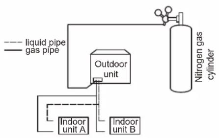
flowchart
graph TD
    A["liquid pipe"] --> B["Outdoor unit"]
    C["gas pipe"] --> B
    B --> D["Nitrogen gas cylinder"]
    E["Indoor unit A"] --> B
    F["Indoor unit B"] --> B
Figure 5.15
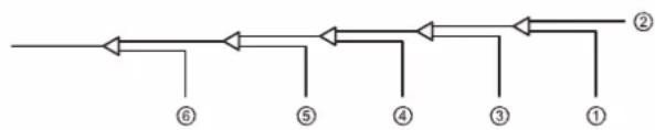
flowchart
graph LR
    A["Start"] --> B["Step ⑥"]
    B --> C["Step ⑤"]
    C --> D["Step ④"]
    D --> E["Step ③"]
    E --> F["Step ②"]
    F --> G["Step ①"]
Figure 5.16
5.6 Gastightness Test
To prevent faults caused by refrigerant leakage, a gastightness test should be performed before system commissioning.

Caution
- Only dry nitrogen should be used for gastightness testing. Oxygen, air, flammable gases and toxic gases must not be used for gastightness testing. Use of such gases may result in fire or explosion.
- Make sure that all the outdoor unit stop valves are firmly closed.
The gastightness test procedure is as follows:
- Once the piping system is complete and the indoor and outdoor units have been connected, vacuum the piping to -0.1Mpa.
- Charge the indoor piping with nitrogen at 0.3Mpa through the needle valves on the liquid and gas stop valves and leave for at least 3 minutes (do not open the liquid or gas stop valves). Observe the pressure gauge to check for large leakages. If there is a large leakage, the pressure gauge will drop quickly.
- If there are no large leakages, charge the piping with nitrogen at 1.5Mpa and leave for at least 3 minutes. Observe the pressure gauge to check for small leakages. If there is a small leakage, the pressure gauge will drop distinctly.
- If there are no small leakages, charge the piping with nitrogen at 4.2 MPa and leave for at least 24 hours to check for micro leakages. Micro leakages are difficult to detect. To check for micro leakages, allow for any change in ambient temperature over the test period by adjusting the reference pressure by 0.01Mpa per 1°C of temperature difference. Adjusted reference pressure = Pressure at pressurization + (temperature at observation – temperature at pressurization) x 0.01Mpa. Compare the observed pressure with the adjusted reference pressure. If they are the same, the piping has passed the gastightness test. If the observed pressure is lower than the adjusted reference pressure, the piping has a micro leakage.
- If the leakage is detected, refer to following part "Leak detection". Once the leak has been found and fixed, the gastightness test should be repeated.
- If not continuing straight to vacuum drying once the gastightness test is complete, reduce the system pressure to 0.5-0.8Mpa and leave the system pressurized until ready to carry out the vacuum drying procedure
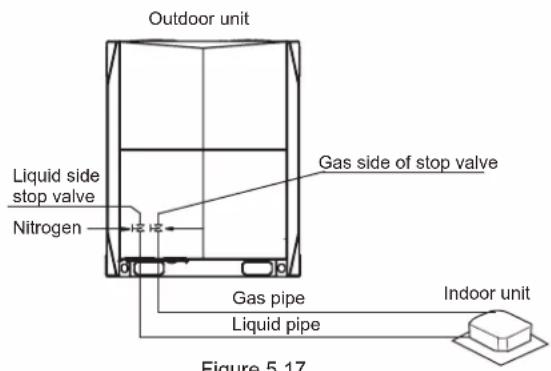
Figure 5.17
Leak detection
The general methods for identifying the source of a leak are as follows:
- Audio detection: relatively large leaks are audible.
- Touch detection: place your hand at joints to feel for escaping gas.
- Soapy water detection: small leaks can be detected by the formation of bubbles when soapy water is applied to a joint.
5.7 Vacuum Drying
Vacuum drying should be performed in order to remove moisture and non-condensable gases from the system. Removing moisture prevents ice formation and oxidization of copper piping or other internal components. The presence of ice particles in the system would cause abnormal operation, whilst particles of oxidized copper can cause compressor damage. The presence of non-condensable gases in the system would lead to pressure fluctuations and poor heat exchange performance.
Vacuum drying also provides additional leak detection (in addition to the gastightness test).

Caution
- Before performing vacuum drying, make sure that all the outdoor unit stop valves are firmly closed.
- Once the vacuum drying is complete and the vacuum pump is stopped, the low pressure in the piping could suck vacuum pump lubricant into the air conditioning system. The same could happen if the vacuum pump stops unexpectedly during the vacuum drying procedure. Mixing of pump lubricant with compressor oil could cause compressor malfunction and a one-way valve should therefore be used to prevent vacuum pump lubricant seeping into the piping system.
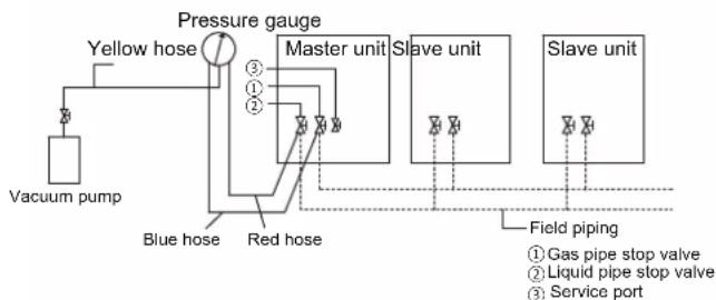
During vacuum drying, a vacuum pump is used to lower the pressure in the piping to the extent that any moisture present evaporates. At 5mmHg (755mmHg below typical atmospheric pressure) the boiling point of water is 0°C. Therefore a vacuum pump capable of maintaining a pressure of -756mmHg or lower should be used. Using a vacuum pump with a discharge in excess of 4L/s and a precision level of 0.02mmHg is recommended. The vacuum drying procedure is as follows:
- Connect the blue (low pressure side) hose of a pressure gauge to the master unit gas pipe stop valve, the red (high pressure side) hose to the master unit liquid pipe stop valve and the yellow hose to the vacuum pump.
- Start the vacuum pump and then open the pressure gauge valves to start vacuum the system.
- After 30 minutes, close the pressure gauge valves.
- After a further 5 to 10 minutes check the pressure gauge. If the gauge has returned to zero, check for leakages in the refrigerant piping.
- Re-open the pressure gauge valves and continue vacuum drying for at least 2 hours and until a pressure difference of 0.1Mpa or more has been achieved. Once the pressure difference of at least 0.1Mpa has been achieved, continue vacuum drying for 2 hours.
- Close the pressure gauge valves and then stop the vacuum pump.
- After 1 hour, check the pressure gauge. If the pressure in the piping has not increased, the procedure is finished. If the pressure has increased, check for leakages.
- After vacuum drying, keep the blue and red hoses connected to the pressure gauge and to the master unit stop valves, in preparation for refrigerant charging.
flowchart
graph TD
    A["Vacuum pump"] --> B["Yellow hose"]
    B --> C["Pressure gauge"]
    C --> D["Master unit"]
    D --> E["Slave unit"]
    E --> F["Slave unit"]
    C --> G["Blue hose"]
    C --> H["Red hose"]
    G --> I["Field piping"]
    H --> I
    style A fill:#f9f,stroke:#333
    style B fill:#ccf,stroke:#333
    style C fill:#cfc,stroke:#333
    style D fill:#fcc,stroke:#333
    style E fill:#cff,stroke:#333
    style F fill:#ffc,stroke:#333
    style G fill:#cfc,stroke:#333
    style H fill:#cfc,stroke:#333
    style I fill:#fcc,stroke:#333
Figure 5.18
5.8 Piping Insulation
After the leak test and the vacuum drying are completed, the pipe must be insulated. Considerations:
- Make sure the refrigerant piping and branch joints are completely insulated.
- Make sure the liquid and gas pipes (for all units) are insulated.
- Use heat-resistant polyethylene foam for the liquid pipes (able to withstand temperature of 70^ ), and polyethylene foam for the gas pipes (able to withstand temperature of 120^ ).
- Reinforce the insulation layer of the refrigerant piping based on the installation environment.
Condensed water may form on the surface of the insulation layer.
| Piping size | Humidity<80%RH Thickness | Humidity≥80%RH Thickness |
| Φ6.4~38.1mm ≥15mm | ≥20mm | |
| Φ41.3~54.0mm | ≥20mm | ≥25mm |
5.9 Refrigerant Charging

Warning
- Use only R410A as the refrigerant. Other substances may cause explosions and accidents.
- R410A contains fluorinated greenhouse gases, and the GWP value is 2088. Do not discharge the gas into the atmosphere.
- When charging the refrigerant, make sure you wear protective gloves and safety glasses. Be careful when you open the refrigerant piping.

Note
- If the power supply of some units is off, the charging program cannot be completed normally.
- If this is a multi-unit outdoor system, the power supply for all outdoor units should be turned on.
- Make sure the power supply is turned on 12 hours before operations so that the crankcase heater is properly energized. This is also to protect the compressor.
- Make sure all connected indoor units have been identified.
- Charge the refrigerant only after the system has not failed the gas tightness tests and vacuum drying.
- Volume of refrigerant charged must not exceed the designed amount.
Calculating additional refrigerant charge
The additional refrigerant charge required depends on the lengths and diameters of the outdoor and indoor liquid pipes. Table below shows the additional refrigerant charge required per meter of equivalent pipe length for different diameters of pipe. The total additional refrigerant charge is obtained by summing the additional charge requirements for each of the outdoor and indoor liquid pipes, as in the following formula, where T1 to T8 represent the equivalent lengths of the pipes of different diameters. Assume 0.5m for the equivalent pipe length of each branch joint.
| Liquid side piping (mm) | Additional refrigerant charge per meter of equivalent length of piping (kg) |
| Φ6.4 | 0.022kg |
| Φ9.53 | 0.057kg |
| Φ12.7 | 0.110kg |
| Φ15.9 | 0.170kg |
| Φ19.1 | 0.260kg |
| Φ22.2 | 0.360kg |
| Φ25.4 | 0.520kg |
| Φ28.6 | 0.680kg |
Additional refrigerant charge R (kg) = (T1@Φ6.4) × 0.022 + (T2@Φ9.53) × 0.057 + (T3@Φ12.7) × 0.110 + (T4@Φ15.9) × 0.170 + (T5@Φ19.1) × 0.260 + (T6@Φ22.2) × 0.360 + (T7@Φ25.4) × 0.520 + (T8@Φ28.6) × 0.680
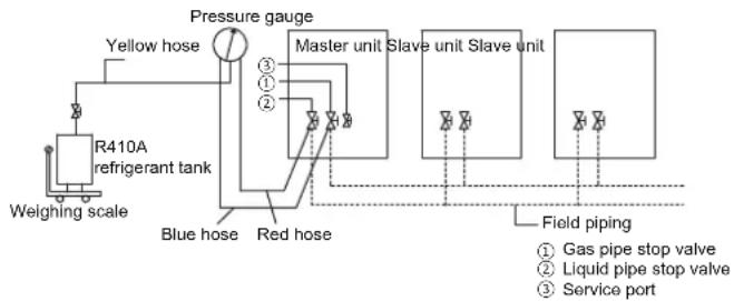
The procedure for adding refrigerant is as follows:
- Calculate additional refrigerant charge R (kg).
- Place a tank of R410A refrigerant on a weighing scale. Turn the tank upside down to ensure refrigerant is charged in a liquid state. (R410A is a blend of two different chemicals compounds. Charging gaseous R410A into the system could mean that the refrigerant charged is not of the correct composition).
- After vacuum drying, the blue and red pressure gauge hoses should still be connected to the pressure gauge and to the master unit stop valves.
- Connect the yellow hose from the pressure gauge to the R410A refrigerant tank.
- Open the valve where the yellow hose meets the pressure gauge, and open the refrigerant tank slightly to let the refrigerant eliminate the air. Caution: open the tank slowly to avoid freezing your hand.
- Set the weighing scale to zero.
- Open the three valves on the pressure gauge to begin charging refrigerant.
- When the amount charged reaches R (kg), close the three valves. If the amount charged has not reached R (kg) but no additional refrigerant can be charged, close the three valves on the pressure gauge, run the outdoor units in cooling mode, and then open the yellow and blue valves. Continue charging until the full R (kg) of refrigerant has been charged, then close the yellow and blue valves. Note: Before running the system, be sure to complete all the pre-commissioning checks and be sure to open all stop valves as running the system with the stop valves closed would damage the compressor.
flowchart
graph TD
    A["Weighing scale"] --> B["R410A refrigerant tank"]
    B --> C["Yellow hose"]
    C --> D["Pressure gauge"]
    D --> E["Master unit"]
    E --> F["Slave unit Slave unit"]
    F --> G["Field piping"]
    G --> H["Service port"]
    I["Blue hose"] --> J["Red hose"]
    K["Gas pipe stop valve"] --> L["①"]
    M["Liquid pipe stop valve"] --> N["②"]
    O["③"] --> P["④"]
    Q["⑤"] --> R["⑥"]
Figure 5.19
5.10 Electrical Wiring
5.10.1 Electrical wiring precautions

Warning
- Take note of the risk of electric shocks during installation.
- All the electric wires and components must be installed by an installation personnel with the proper electrician certification, and the installation process must comply with the applicable regulations.
- Use only wires with copper cores for the connections.
- A main switch or safety device that can disconnect all polarities must be installed, and the switching device can be completely disconnected when the corresponding excessive voltage situation arises.
- Wiring must be carried out in strict accordance with what is stated in the product nameplate.
- Do not squeeze or pull the unit connection, and make sure the wiring is not in contact with the sharp edges of the sheet metal.
- Make sure the grounding connection is safe and reliable. Do not connect the earth wire to public pipes, telephone earth wires, surge absorbers and other places that are not designed for grounding. Improper grounding may cause electric shock.
- Make sure the fuses and circuit breakers installed meet the corresponding specifications.
- Make sure an electric leakage protection device is installed to prevent electric shocks or fires.
- The model specifications and characteristics (anti high-frequency noise characteristics) of the electric leakage protection device are compatible with the unit to prevent frequent tripping.
- Before power on, make sure the connections between the power cord and terminals of the components are secure, and the metallic cover of the electric control box is closed tightly.

Note
- If the power supply lacks N phase or there is an error in the N phase, the device will malfunction.
- This product comes with a three-phase detection circuit that is used to check if the wiring is reversed when the unit is power on.
- The three-phase detection circuit only works when the product is in standby status. It cannot conduct the reverse phase checking when the product is operating normally.
- If the reverse-phase protection is triggered, you only need to replace any two of the three phases (A, B, C).
- Some power equipment may have an inverted phase or intermittent phase (such as a generator). For this type of power sources, a reverse-phase protection circuit should be installed locally in the unit, as operating in the inverted phase may damage the unit.
- Do not share the same power supply line with other devices.
- The power cord may produce electromagnetic interference so you should maintain a certain distance from equipment that may be susceptible to such interference.
- Indoor units in the same system must be powered by the same power supply, in order not to damage the system.
- Separate power supply for the indoor and outdoor units.
- For systems with multiple units, make sure a different address is set for each outdoor unit.
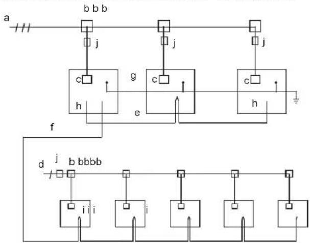
Wiring layout comprises of the power cords and communication wiring between the indoor and outdoor units. These include the earth lines, and the shielded layer of the earth lines of the indoor units in the P,Q,E communication line. See below for an example of a wiring layout.
flowchart
graph TD
    a --> b["Switch b"]
    b --> j1["j"]
    b --> j2["j"]
    b --> j3["j"]
    b --> j4["j"]
    b --> j5["j"]
    b --> j6["j"]
    b --> j7["j"]
    b --> j8["j"]
    b --> j9["j"]
    b --> j10["j"]
    b --> j11["j"]
    b --> j12["j"]
    b --> j13["j"]
    b --> j14["j"]
    b --> j15["j"]
    b --> j16["j"]
    b --> j17["j"]
    b --> j18["j"]
    b --> j19["j"]
    b --> j20["j"]
    b --> j21["j"]
    b --> j22["j"]
    b --> j23["j"]
    b --> j24["j"]
    b --> j25["j"]
    b --> j26["j"]
    b --> j27["j"]
    b --> j28["j"]
    b --> j29["j"]
    b --> j30["j"]
    b --> j31["j"]
    b --> j32["j"]
    b --> j33["j"]
    b --> j34["j"]
    b --> j35["j"]
    b --> j36["j"]
    b --> j37["j"]
    b --> j38["j"]
    b --> j39["j"]
    b --> j40["j"]
    b --> j41["j"]
    b --> j42["j"]
    b --> j43["j"]
    b --> j44["j"]
    b --> j45["j"]
    b --> j46["j"]
    b --> j47["j"]
    b --> j48["j"]
    b --> j49["j"]
    b --> j50["j"]
    b --> j51["j"]
    b --> j52["j"]
    b --> j53["j"]
    b --> j54["j"]
    b --> j55["j"]
    b --> j56["j"]
    b --> j57["j"]
    b --> j58["j"]
    b --> j59["j"]
    b --> j60["j"]
    b --> j61["j"]
    b --> j62["j"]
    b --> j63["j"]
    b --> j64["j"]
    b --> j65["j"]
    b --> j66["j"]
    b --> j67["j"]
    b --> j68["j"]
    b --> j69["j"]
    b --> j70["j"]
    b --> j71["j"]
    b --> j72["j"]
    b --> j73["j"]
    b --> j74["j"]
    b --> j75["j"]
    b --> j76["j"]
    b --> j77["j"]
    b --> j78["j"]
    b --> j79["j"]
    b --> j80["j"]
    b --> j81["j"]
    b --> j82["j"]
    b --> j83["j"]
    b --> j84["j"]
    b --> j85["j"]
    b --> j86["j"]
    b --> j87["j"]
    b --> j88["j"]
    b --> j89["j"]
    b --> j90["j"]
    b --> j91["j"]
    b --> j92["j"]
    b --> j93["j"]
    b --> j94["j"]
    b --> j95["j"]
    b --> j96["j"]
    b --> j97["j"]
    b --> j98["j"]
    b --> j99["j"]
a. Three-phase power supply (with earth lines and leakage protection)
b. Power distribution box
c. Power supply terminal of outdoor unit
d. Single phase power supply (with earth lines and leakage protection)
e. H1, H2 and E communication wire(with shielded layer)
f. P, Q and E communication wire(with shielded layer)
g. Earth line
h. Outdoor unit
i. Indoor unit
j. Main switch (with leakage protection)
Figure 5.20
5.10.3 About wiring layout

Note
- Power cords and communication wiring must be laid out separately, they cannot be placed in the same conduit. Use a power supply conduit to isolate if the current of the power supply is less than 10 A. If the current is greater than 10 A but less than 50 A, the spacing must exceed 500 mm at all times; otherwise; it may lead to electromagnetic interference.
- Arrange the refrigerant piping, power cords and communication wiring in parallel, but do not tie the communication lines together with the refrigerant piping or power cords.
- Power cords and communication wiring should not come in contact with the internal piping so as to prevent the high temperature piping from damaging the wires.
- Once the wiring layout is completed, close the lid tightly to prevent the wiring and terminals from being exposed when the lid is loose.
5.10.4 Communication wiring layout
Communication wiring of indoor unit: The P,Q,E communication line should be connected in a chain starting from the outdoor unit to each indoor unit one by one up to the last indoor unit. In the last indoor unit, connect a resistor of 120 ohms between the P and Q terminals. The correct and wrong connection methods are demonstrated below:

flowchart
graph TD
    A["Master unit"] -->|PQE| B["Indoor unit"]
    B --> C["PQE"]
    C --> D["Indoor unit"]
    D --> E["PQE"]
    E --> F["Indoor unit"]
    F --> G["PQE"]
    G -.-> H["Indoor unit"]
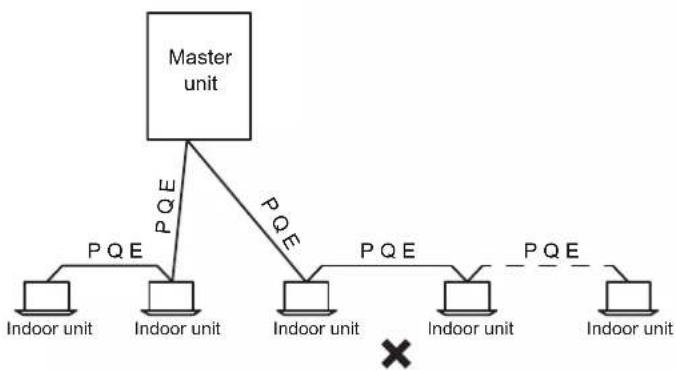
flowchart
graph TD
    A["Master unit"] -->|PQE| B["Indoor unit"]
    A -->|PQE| C["Indoor unit"]
    A -->|PQE| D["Indoor unit"]
    A -->|PQE| E["Indoor unit"]
    A -->|PQE| F["Indoor unit"]
    B --> G["×"]
    C --> G
    D --> G
    E --> G
    F --> G
Do not connect two chains from one outdoor unit.
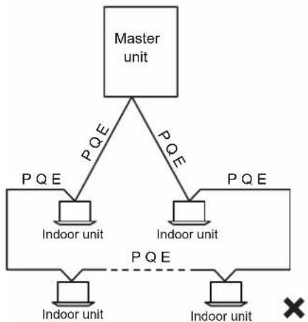
flowchart
graph TD
    A["Master unit"] -->|PQE| B["Indoor unit"]
    A -->|PQE| C["Indoor unit"]
    A -->|PQE| D["Indoor unit"]
    B --> E["PQE"]
    C --> F["PQE"]
    D --> G["PQE"]
    style A fill:#f9f,stroke:#333
    style B fill:#ccf,stroke:#333
    style C fill:#ccf,stroke:#333
    style D fill:#ccf,stroke:#333
    style E fill:#dfd,stroke:#333
    style F fill:#dfd,stroke:#333
    style G fill:#dfd,stroke:#333
Figure 5.21
After the last indoor unit, the communication wiring should not route back to the outdoor unit as this will form a closed loop.
Communication wiring of outdoor unit: The H1H2E communication lines of the outdoor unit should be connected in a chain starting from the master unit to the last slave unit. As shown below.
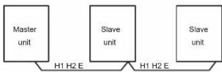
flowchart
graph LR
    A["Master unit"] -->|H1 H2 E| B["Slave unit"]
    B -->|H1 H2 E| C["Slave unit"]
Figure 5.22

Note
- Three-core shielded cable should be used for communication wiring. The cross-sectional area of each core of the communication wiring is not less than 0.75 ~mm^2 , and the length must not exceed 1200 ~m . A communication error may result when the communication wiring exceeds these limitations.
5.10.4.2 Place and fix communication wiring
Place the communication wiring along the front of the unit, and secured with a corresponding tie.
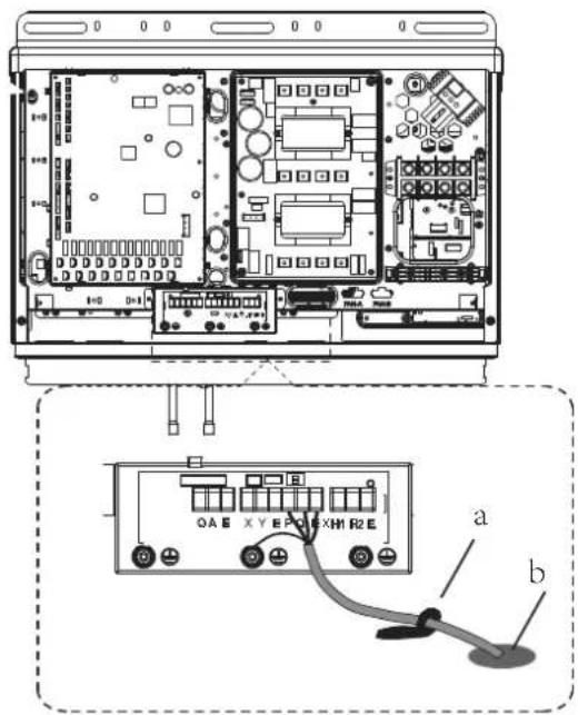
a. Wire clamp
b. Via for communication wiring
Figure 5.23
5.10.4.3 Communications wiring
The communication wiring of the indoor unit must be connected to the P,Q,E terminal on the PCB of the communication terminals block of the outdoor unit. The communication wiring between outdoor units must be connected to the H1,H2,E terminals on the PCB of the communication terminals block of the outdoor unit.
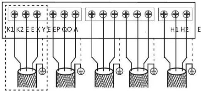
Figure 5.24
communication connections
| Terminals | Connection |
| K1 K2 E | Connect to outdoor unit centralized monitor (Suitable for some models) |
| O A E | Connect to digital energy meter |
| X Y E | Connect to indoor unit centralized controller |
| P Q E | Connect between indoor units and master outdoor unit |
| H1 H2 E | Connect between outdoor units |
When fixing the communication wiring, the height on both sides of the clamp should be the same so as to avoid any height difference when all are placed together on one side or both sides. as shown below:
● : Communication wire
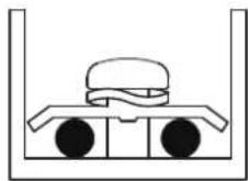
Proper communication wiring connections
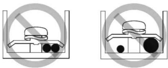
natural_image
Two identical diagrams showing a container with a bag and two circular objects inside, enclosed by a prohibition symbol (no text or labels)Improper communication wiring connections
Figure 5.25
Installation of a single outdoor unit is as below:
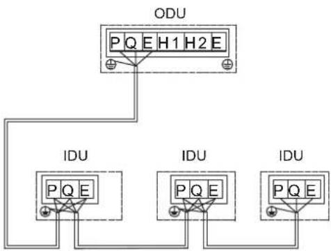
flowchart
graph TD
    A["ODU"] --> B["IDU"]
    A --> C["IDU"]
    A --> D["IDU"]
    B --> E["PQ E"]
    C --> F["PQ E"]
    D --> G["PQ E"]
Figure 5.26
Installation of multiple outdoor units is as below:
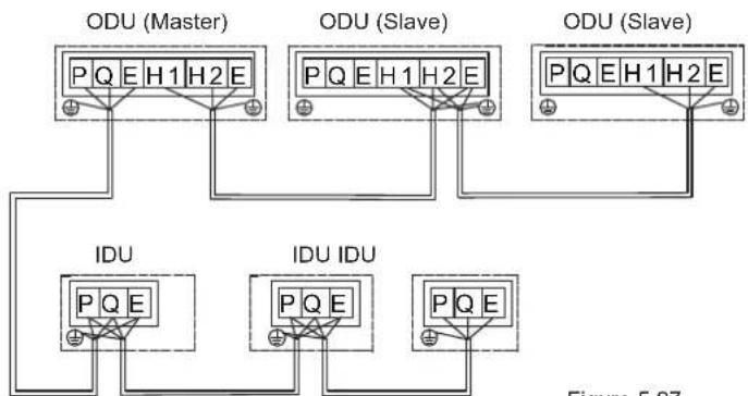
flowchart
graph TD
    subgraph ODU (Master)
        A["ODU (Master)"] --> B["PQ E H1 H2 E"]
        C["ODU (Slave)"] --> D["PQ E H1 H2 E"]
        E["ODU (Slave)"] --> F["PQ E H1 H2 E"]
    end
    subgraph IDU
        G["IDU"] --> H["PQ E"]
        I["IDU IDU"] --> J["PQ E"]
        K["Figure 5.37"]
Figure 5.27
The recommend tightening torque for the communication terminals block is as follows:
| Screw Specification | Tightening torque, N.m |
| M3 | 0.5~0.6 |

Note
When there are multiple outdoor units in the same system,
- the H1,H2,E of one unit must be connected to the H1,H2,E of another unit. Connection to the P,Q,E will cause a system malfunction.
In systems with multiple outdoor units, each outdoor unit
- should be set address. Only the master outdoor unit can communicate with indoor units.
Before the performance test, set the number of the indoor unit, the address of the outdoor unit and so on. After the test
- run is completed, you cannot randomly change these DIP switches.
5.10.5 Connecting the power cord
5.10.5.1 Fixing the power cord
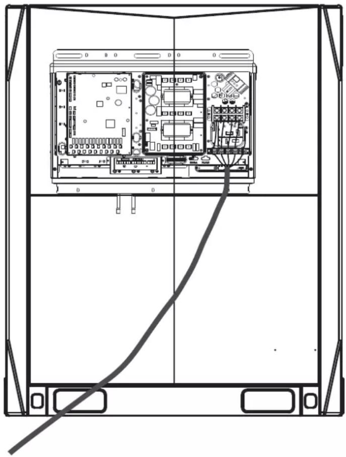
natural_image
Technical line drawing of a server rack with internal circuit board and cable (no text or symbols)Figure 5.28
5.10.5.2 Power cord connections

Note
- Do not connect the power supply to the terminal box of the communication box. Otherwise, the whole system may fail.
- You must first connect the earth line (note that you should use only the yellow-green wire to connect to earth, and you must turn off the power supply when you are connecting the earth line) before you connect the power cord. Before you install the screws, you must first comb through the path along the wiring to prevent any part of the wiring from becoming exceptionally loose or tight because the lengths of the power cord and earth line are not consistent.
- The wire diameter must comply with the specified specification, and make sure the terminal is screwed tight. At the same time, do not subject the terminal to any external force.
- Do tighten the terminal with an appropriate screwdriver. Screwdrivers that are too small may damage the terminal head, and cannot tighten it.
- Excessive tightening of the terminal may cause the screw thread to deform and slip, making it impossible to connect the components securely.
- Only use a ring terminal to connect the power cord. Non-standard cable connection will lead to poor contact which may in turn cause exceptional heating and burning. The figure below demonstrates both the correct and wrong connections.
Power supply
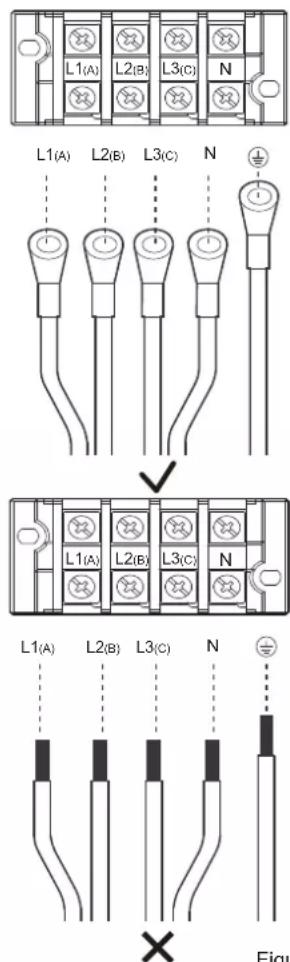
Figure 5.29
The size of the screws (power supply terminal specifications) and recommended torque are as follows:
| Screw Specification | Tightening torque, N.m |
| M8 | 5.5~7.0 |
Steps to fix the power cord:
- First, peel part of the skin of the outermost insulating layer (refer to the third point below for the specific length). Connect the power cable to the terminal, and install the screws.
- Position the wire clip. Be careful not to reverse the first step, or it will be difficult to install the screws.
- The wire clip has been fixed at a position on the sheet metal near the terminal of the electric control box. Put the power cable in the corresponding slot between the base and upper cover. Select the appropriate slot based on the specific diameter of the cable. When the cross-sectional area of the power cable is less than 10 mm², place the entire power cord inside the slot. At this time, make sure both the length of the peel and the length of the terminal are less than 70 mm, as shown below.
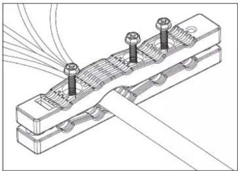
natural_image
Technical line drawing of a mechanical assembly with bolts and wires (no text or symbols)Figure 5.30
When the cross sectional area of the power cable exceeds 10 mm^2 , place the power cables separately in the slot. When the skin is peeled, make sure the sum of the length of the peel and the length of the terminal is between 100 mm and 200 mm, as shown below.
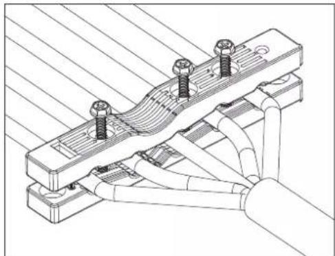
natural_image
Technical line drawing of a mechanical assembly with bolts and tubing (no text or symbols)Then, use 3 pieces of M4*30mm screws to secure the upper cover. At the same time, be careful not to screw it too tight. If you use excessive force to twist to the end, you may destroy the protection layer of the power cable.
Figure 5.31

Note
- Do not connect the power cables of multiple outdoor units in series. The power cable of each outdoor unit must be drawn out by the power supply control box.
6 Configuration
6.1 Overview
This chapter describes how the system configuration can be implemented once the installation is complete, and other relevant information.
It contains the following information:
- Implement field settings
- Energy-saving and optimized operation
- Using the Leak Check function

Information
The installation personnel should read this chapter.
6.2 Dial Switch Settings
Dial code definitions:

means 0

means 1
| S4 |  | 000 | Standard static pressure (default) |
| 001 | Low static pressure mode (reserved) | ||
| 010 | Medium static pressure mode (reserved) | ||
| 011 | High static pressure mode (reserved) | ||
| 100 | Super high static pressure mode (reserved) | ||
| S5 |  | 000 | Auto priority (default) |
| 001 | Cooling priority | ||
| 010 | VIP priority or voting priority | ||
| 011 | Heating only | ||
| 100 | Cooling only | ||
| 111 | Set priority mode via centralized controller | ||
| S6-1 |  | 0 | Reserved |
| S6-2 |  | 0 | No action (default) |
| 1 | Clear indoor unit addresses | ||
| S6-3 |  | 0 | Auto addressing (default) |
| 1 | Manual addressing | ||
| S8-1 |  | 0 | Reserved |
| S8-2 |  | 0 | Start-up time is 12 minutes (default) |
| 1 | Start-up time is 7 minutes | ||
| S8-3 |  | 0 | Reserved |
| S7 |  | 0 | Reserved |
| S13 |  | 0 | Use the new centralized controller (default) |
| 1 | Use the old centralized controller | ||
| ENC1 | [ASXV] | 0-2 | Outdoor unit address setting, Only 0, 1, 2 should be selected(default is 0)0 is for master unit; 1, 2 are for slave units. |
| ENC2 | [DSAH] | 0-C | Outdoor unit capacity setting, Only 0 to C should be selected 0 to C are for 8HP to 32HP. |
| ENC4 | [TCCZ] | 0-7 | Outdoor unit network address setting, Only 0 to 7 should be selected (default is 0). |
| ENC3 &S12 | [YYKA] | 0-F | The number of indoor units is in the range 0-150-9 on ENC3 indicate 0-9 indoor units;A-F on ENC3 indicate 10-15 indoor units |
| [6CAZ] | 000 | ||
| [TTXK] | 0-F | The number of indoor units is in the range 16-310-9 on ENC3 indicate 16-25 indoor units;A-F on ENC3 indicate 26-31 indoor units | |
| [OX3T] | 001 | ||
| [WZTW] | 0-F | The number of indoor units is in the range 32-470-9 on ENC3 indicate 32-41 indoor units;A-F on ENC3 indicate 42-47 indoor units | |
| [WCZS] | 010 | ||
 | 0-F | The number of indoor units is in the range 48-630-9 on ENC3 indicate 48-57 indoor units;A-F on ENC3 indicate 58-63 indoor units | |
| [5CHI] | 011 | ||
| ENC5 | [KBW8] | 0 | Night silent time is 6h/10h (default) |
| 1 | Night silent time is 6h/12h | ||
| 2 | Night silent time is 8h/10h | ||
| 3 | Night silent time is 8h/12h | ||
| 4 | No silent mode | ||
| 5 | Silent mode 1 (only limit max. fan speed) | ||
| 6 | Silent mode 2 (only limit max. fan speed) | ||
| 7 | Silent mode 3 (only limit max. fan speed) | ||
| 8 | Super silent mode 1 (limit max. fan speed and compressor frequency) | ||
| 9 | Super silent mode 2 (limit max. fan speed and compressor frequency) | ||
| A | Super silent mode 3 (limit max. fan speed and compressor frequency) | ||
| B | Super silent mode 4 (limit max. fan speed and compressor frequency) | ||
| F | Set silent mode via centralized controller |
6.3 Digital Display and Button Settings
DSP1 DSP2
SW5 SW4 SW3 SW6
MENU DOWN UP OK
6.3.1 Digital display output
| Outdoor unit state | Parameters displayed on DSP1 | Parameters displayed on DSP2 | |
| Standby | Unit's address | The number of indoor units in communication with the outdoor units | |
| Normal operation | For single compressor units | -- | Running speed of the compressor in rotations per second |
| For dual compressor units | Running speed of compressor B in rotations per second | Running speed of compressor A in rotations per second | |
| Error or protection | -- or placeholder | Error or protection code | |
| In menu mode | Display menu mode code | ||
| System check | Display system check code | ||
6.3.2 Function of buttons SW3 to SW6
| Button Function | |
| SW3 (UP) | In menu mode: previous and next buttons for menu modes. |
| SW4 (DOWN) | Not in menu mode: previous and next buttons for system check information. |
| SW5 (MENU) | Enter / exit menu mode. |
| SW6 (OK) | Confirm to enter specified menu mode. |

Note
- Operate the switches and push buttons with an insulated stick (such as a closed ball-point pen) to avoid touching of live parts.
6.3.3 Menu mode
Only master unit has the full menu functions, slaves units only have error codes check and cleaning functions.
- Long press SW5 "MENU" button for 5 seconds to enter menu mode, and the digital display displays "n1";
- Press SW3 / SW4 "UP / DOWN" button to select the first level menu "n1", "n2", "n3", "n4" or "nb";
- Press SW6 "OK" button to enter specified first level menu, for example, enter "n4" mode;
- Press SW3 / SW4 "UP / DOWN" button to select the second level menu from "n41" to "n47";
- Press SW6 "OK" button to enter specified second level menu, for example, enter "n43" mode;
Menu mode selection flowchart:
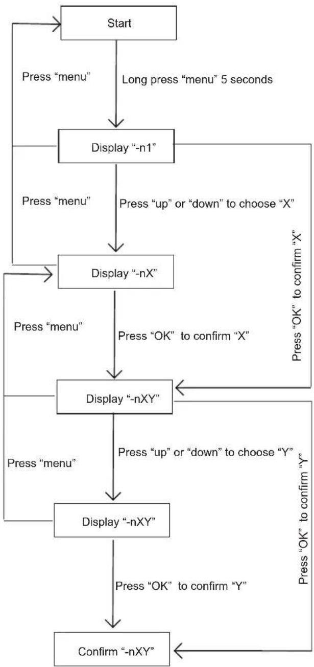
flowchart
graph TD
    A["Start"] --> B["Press "menu""]
    B --> C["Display "-n1""]
    C --> D["Press "up" or "down" to choose "X""]
    D --> E["Display "-nX""]
    E --> F["Press "OK" to confirm "X""]
    F --> G["Display "-nXY""]
    G --> H["Press "up" or "down" to choose "Y""]
    H --> I["Display "-nXY""]
    I --> J["Press "OK" to confirm "Y""]
    J --> K["Confirm "-nXY""]
    K --> L["Press "menu""]
    L --> M["Display "-nX""]
    M --> N["Press "up" or "down" to choose "X""]
    N --> O["Display "-nX""]
    O --> P["Press "OK" to confirm "X""]
    P --> Q["Display "-nXY""]
    Q --> R["Press "OK" to confirm "Y""]
    R --> S["Confirm "-nXY""]
    S --> T["Press "OK" to confirm "Y""]
| DescriptionMENU | Note | |
| n14 | Debug mode 1 | 1 |
| n15 | Debug mode 2 | 2 |
| n16 | Maintenance mode | 3 |
| n24 | Reserved | |
| n25 | Reserved | |
| n26 | Backup run | 4 |
| n27 | Vacuum mode | Display“R006” |
| n31 | History codes | |
| n32 | Cleaning history error | |
| n33 | Reserved | |
| n34 | Restore factory settings | 5 |
| n41 | Power limitation mode 1 | 6 |
| n42 | Power limitation mode 2 | 7 |
| n43 | Power limitation mode 3 | 8 |
| n44 | Power limitation mode 4 | 9 |
| n45 | Power limitation mode 5 | 10 |
| n46 | Power limitation mode 6 | 11 |
| n47 | Power limitation mode 7 | 12 |
| nb1 | Fahrenheit degree (°F) | Only available for master unit |
| nb2 | Celsius degree (°C) | Only available for master unit |
| nb3 | Exit auto energy saving mode | Only available for master unit |
| nb4 | Enter auto energy saving mode | Only available for master unit |
| nb5 | Auto snow-blowing mode 1 | |
| nb6 | Auto snow-blowing mode 2 | |
| nb7 | Exit auto snow-blowing mode | |
| nb8 | VIP address setting | |
| nF1 | Reserved | |
| nF2 | Reserved |
① Only available for master unit(all indoor units running in cooling mode)
② Only available for master unit(if all the indoor unit in the system are the 2nd generation indoor units, all the indoor units will run in heating mode. Once there is one or more old indoor unit in the system, all the indoor units will run in force cooling mode)
3 Only available for the master unit, the system does not check the indoor units' number.
4 Only available for outdoor unit with two compressors. If one of the two compressors is fail, the other compressor will keep running for up to 4 days and then stop automatically.
⑤ Only available for the master unit
6 Only available for the master unit, 100% capacity output
⑦ Only available for the master unit, 90% capacity output
8 Only available for the master unit, 80% capacity output
9 Only available for the master unit, 70% capacity output
10 Only available for the master unit, 60% capacity output
11 Only available for the master unit, 50% capacity output
12 Only available for the master unit, 40% capacity output
6.3.4 UP / DOWN system check button
Before pressing UP or DOWN button, allow the system to operate steadily for more than an hour. On pressing UP or DOWN button, the parameters listed in below table will be displayed in sequence.
| DSP1 content | Parameters displayed on DSP2 Remarks | |
| 0 | Unit address | 0-2 |
| 1 | Unit capacity | 8-32HP |
| 2 | Number of outdoor units | 1 |
| 3 | Number of indoor units as set on PCB | 1 |
| 4 | Total capacity of outdoor unit | 2 |
| 5 | Total capacity requirement of indoor units | 1 |
| 6 | Total capacity requirement correction of master unit | 1 |
| 7 | Operating mode | 3 |
| 8 | Outdoor unit actual operating capacity | |
| 9 | Fan A speed index | |
| 10 | Fan B speed index | |
| 11 | T2/T2B average Temp (°C) | |
| 12 | Main heat exchanger pipe(T3) temperature (°C) | |
| 13 | Outdoor ambient(T4) temperature (°C) | |
| 14 | Plate heat exchanger cooling refrigerant inlet (T6A) temperature (°C) | |
| 15 | Plate heat exchanger cooling refrigerant outlet (T6B) temperature (°C) | |
| 16 | Discharge Temp. of compressor A (°C) | |
| 17 | Discharge Temp. of compressor B (°C) | |
| 18 | Inverter-module heatsink Temp. A (°C) | |
| 19 | Inverter-module heatsink Temp. B (°C) | |
| 20 | Plate exchanger degree of superheat (°C) | |
| 21 | Discharge superheat degree | |
| 22 | Inverter compressor A current (A) | |
| 23 | Inverter compressor B current (A) | |
| 24 | EEVA position | 4 |
| 25 | EEVB position | 4 |
| 26 | EEVC position | 5 |
| 27 | Compressor discharge pressure (Mpa) | 6 |
| 28 | Reserved | Reserved |
| 29 | Number of indoor units currently in communication with master unit | |
| 30 | Number of indoor units currently operating | 1 |
| 31 | Priority mode | 7 |
| 32 | Silent mode | 8 |
| 33 | Static pressure mode | 9 |
| 34 | Reserved | |
| 35 | Reserved | |
| 36 | DC bus voltage A | 10 |
| 37 | DC bus voltage B | 10 |
| 38 | Reserved | |
| 39 | Address of VIP indoor unit | |
| 40 | Reserved | |
| 41 | Reserved | |
| 42 | Refrigerant state | 11 |
| 43 | Reserved | |
| 44 | Power mode | 12 |
| 45 | Most recent error or protection code | |
| -- | -- | Check end |
① Available for master unit
2 Only available for master unit, displayed on slave units has no sense;
③ Operation mode: 0-OFF; 2-Cooling; 3-Heating; 4-Forced cooling
4 Opening angle of EEV: Actual value=Display value*4(480P) or Actual value=Display value*24(3000P)
⑤ Opening angle of EEV: Actual value=Display value*4(480P)
6 High pressure: Actual value=Display value*0.1Mpa
7 Priority mode: 0-Auto priority, 1-cooling priority, 2-VIP priority or voting priority, 3-Heating only, 4-Cooling only
8 Silent mode: 0-Night silent time is 6h/8h, 1-Night silent time is 6h/12h, 2-Night silent time is 8h/10h, 3-Night silent time is 8h/12h, 7-Silent mode 3,8-Super silent mode 1, 9-Super silent mode 2, 10-Super silent mode 3, 11-Super silent mode 4;
9 Static pressure mode: 0-Standard static pressure, 1-Low Static pressure, 2-Medium static pressure, 3-High static pressure, 4-Super high static pressure;
10 DC bus voltage: Actual value=Display value*10 V
11 Refrigerant quantity: 0-Normal, 1-Slightly excessive, 2-Significantly excessive, 11-Slightly insufficient, 12-Significantly insufficient, 13-Critically insufficient.
12 0-100% capacity output, 1-90% capacity output, 2-80% capacity output, 3-70% capacity output, 4-60% capacity output, 5-50% capacity output, 6-40% capacity output. 10-Auto power save mode, 100% capacity output. 11-Auto power save mode, 90% capacity output, 12-Auto power save mode, 80% capacity output, 13-Auto power save mode, 70% capacity output, 14-Auto power save mode, 60% capacity output, 15-Auto power save mode, 50% capacity output, 16-Auto power save mode, 40% capacity output.
7 Commissioning
7.1 Overview
After installation, and once the field settings have been defined, the installation personnel is obliged to verify the correctness of the operations. Hence, you must follow the steps below to perform the test run.
This chapter describes how the test run can be carried out once the installation is complete, and other relevant information.
The test run usually includes the following stages:
- Review the "Checklist Before Test Run".
- Implement the test run.
- If necessary, correct the errors before the test run completes with exceptions.
- Run the system
7.2 Things to Note During Test Run

Warning
During the test run, the outdoor unit operates at the same time with the indoor units connected to it. It is very dangerous to debug the indoor unit during the test run.
Do not insert fingers, sticks, or other items into the air inlet or outlet. Do not remove the fan mesh cover. When the fan rotates at a high speed, it may cause bodily injury.

Note
Note that the required input power may be higher when this unit is run for the first time. This phenomenon is due to the compressor which needs to run for 50 hours before it can achieve a stable operating and power consumption state.
Make sure the power supply is turned on 12 hours before operations so that the crankcase heater is properly energized. This is also to protect the compressor.

Information
The test run can be carried out when the ambient temperature is between -20°C and 35°C.
During the test run, the outdoor and indoor units will start at the same time. Make sure all the preparations for the indoor unit have been completed. Please refer to the installation manual of the indoor unit for the relevant details.
7.3 Checklist Before Test Run
Once this unit is installed, check the following items first. After all the following checks have been completed, you must shut down the unit. This is the only way to start the unit again.
| InstallationCheck if the unit is installed correctly to prevent strange noises and vibrations when the unit starts. | |
| Field wiringBased on the wiring schematic and the relevant regulations, make sure the field wiring is based on the instructions described in section 5.10 on connecting wires. | |
| Power voltageCheck the power voltage on the local power supply board. The voltage must correspond to the voltage on the identification label of this unit. | |
| Earth lineMake sure the earth line is connected correctly, and the grounding terminal is tight. | |
| Insulation test of main circuitUse the megameter of 500V, apply a voltage of 500V DC between the power terminal and the earth terminal. Check that the insulation resistance is above 2 MΩ. Do not use the megameter on the transmission line. | |
| Fuses, circuit breakers, or protection devicesCheck that the fuses, circuit breakers, or locally installed protection devices comply with the size and type specified in section 4.4.2 on the requirements for safety devices. Make sure you use fuses and protection devices. | |
| Internal wiringVisually inspect if the connections between the electrical component box and the interior of the unit is loose, or if the electrical components are damaged. | |
| Piping dimensions and insulationMake sure the installation piping dimensions are correct, and the insulation work can be carried out normally. | |
| Stop valveMake sure the stop valve is open on both the liquid and gas sides. | |
| Equipment damageCheck for damaged components and extruded piping inside the unit. | |
| Refrigerant leakCheck for refrigerant leaks inside the unit. If there is a refrigerant leak, try to repair the leak. If the repair is not successful, please call the local agent. Do not come in contact with the refrigerant leaking from the refrigerant piping connections. It may cause frostbite. | |
| Oil leakCheck if there is oil leaking from the compressor. If there is an oil leak, try to repair the leak. If the repair is not successful, please call the local agent. | |
| Air inlet/outletCheck for paper, cardboard or any other material that may obstruct the air inlet and outlet of the equipment. | |
| Add additional refrigerantThe amount of refrigerant to be added to this unit should be marked on the "Confirmation Table" which is placed at electrical control box front cover. | |
| Installation date and field settingsMake sure the installation date is recorded on the label of the electric control box cover, and the field settings are recorded as well. |
7.4 About Test Run
The following procedures describe the test run of the whole system. This operation checks and determines the following items:
- Check if there is a wiring error (with the communication check of the indoor unit).
- Check if the stop valve is open.
- Determine the length of the pipe.

Information
- Before you start the compressor, it may take 10 minutes to achieve a uniform cooling state.
- During the test run, the sound of the cooling mode in operation or the solenoid valve may become louder, and there may be changes in the displayed indicators. This is not a malfunction.
7.5 Test Run Implementation
1 Make sure all the settings you need to configure are completed. See section 6.2 on the implementation of the field settings.
2 Turn on the power supply of the outdoor unit and the indoor units.

Information
Make sure the power supply is turned on 12 hours before operations so that the crankcase heater is properly energized. This is also to protect the compressor.
7.6 Rectifications after Test Run is Completed with Exceptions
The test run is considered complete when there is no error code on the user interface or the outdoor unit display. When an error code is displayed, rectify the operation based on the description in the error code table. Try to conduct the test run again to check that the exception has been corrected.

Information
Refer to the installation manual of the indoor unit for details on other error codes related to the indoor unit.
7.7 Operating this Unit
Once the installation of this unit is completed, and the test run of the outdoor and indoor units is done, you can start to run the system.
The indoor unit user interface should be connected to facilitate the operations of the indoor unit. Please refer to the installation manual of the indoor unit for more details.
8 Maintenance and Repair

Information
Arrange for the installation personnel or service agent to carry out one maintenance every year.
8.1 Overview
This chapter contains the following information:
- Take electrical hazards preventive measures during system maintenance and repair.
- Recovery operation for refrigerant
8.2 Safety Precautions for Maintenance

Note
Before you carry out any maintenance or repair work, touch the metal parts of the unit to dissipate static electricity and protect the PCB.
8.2.1 Prevent electrical hazards
When maintaining and repairing the inverter:
1 Do not open the cover of the electrical component box within 5 minutes after the power is switched off.
2 Verify that the power supply is switched off before you use the measuring instrument to measure the voltage between the main capacitor and the main terminal ensure that the capacitor voltage in the main circuit is less than 36 VDC. the position of main terminal have been shown in the Wiring nameplate.
3 Before you come in any contact with the circuit board or components (including the terminals), make sure that static electricity in your own body is eliminated. You can touch the sheet metal of the outdoor unit to achieve this. If conditions permit, please wear anti-static bracelet.
4 During maintenance, pull out the plug connecting to the power cord of the fan to prevent the fan from rotating when it is windy outside. The strong winds will cause the fan to rotate and generate electricity which can charge the capacitor or terminals, leading to an electric shock. At the same time, do take note of any mechanical damage. The blades of a high speed rotating fan are very dangerous and cannot be operated by one person alone.
5 Once the maintenance is completed, remember to reconnect the plug to the terminal; otherwise, a fault will be reported for the main control board.
6. When the unit is power on, the fan of the unit with auto snow-blowing function will run periodically, so make sure the power supply is off before touching the unit.
Please refer to the wiring schematic on the back of the box cover of the electrical component box for the relevant details.
9 Error codes
| Error code | Error description | Remarks |
| E0 | Communication error between outdoor units | Only displayed on the slave unit with the error |
| E1 | Phase sequence error | |
| E2 | Communication error between indoor and master unit | Only displayed on the master unit with the error |
| E4 | T3/T4 Temp. sensor error | |
| E5 | Abnormal power supply voltage | |
| E6 | Reserved | Reserved |
| E7 | Discharge Temp. sensor error | |
| E8 | Outdoor unit address error | |
| xE9 | EEPROM mismatch of compressor | |
| xF1 | DC bus voltage error | |
| F3 | T6B Temp. sensor error | |
| F5 | T6A Temp. sensor error | |
| F6 | Electronic expansion valve connection error | |
| xH0 | Communication error between main board and compressor drive board | |
| H2 | Qty. of outdoor unit decreases error | Only displayed on the master unit with the error |
| H3 | Qty. of outdoor unit increases error | Only displayed on the master unit with the error |
| xH4 | Inverter-module protection | |
| H5 | 3 times of P2 protection in 60 minutes | |
| H6 | 3 times of P4 protection in 100 minutes | |
| H7 | Qty. of indoor units mismatching | Only displayed on the master unit with the error |
| H8 | High pressure sensor error | |
| H9 | 10 times of P9 protection in 120 minutes | |
| yHd | Slave unit malfunction(y=1,2 . e.g ,1Hd stands for slave unit 1 error) | Only displayed on the master unit with the error |
| C7 | 3 times of PL protection in 100 minutes | |
| P1 | High pressure protection or discharge Temp. switch protection | |
| P2 | Low pressure protection | |
| xP3 | Compressor current protection | |
| P4 | Discharge Temp. protection | |
| P5 | High Temp. protection of condenser | |
| xP9 | Fan module protection | |
| xPL | Inverter module Temp. protection | |
| PP | Compressor discharge insufficient superheat protection | |
| xL0 | Inverter compressor module error | |
| xL1 | DC bus low voltage protection | |
| xL2 | DC bus high voltage protection | |
| xL4 | MCE error | |
| xL5 | Zero speed protection | |
| xL7 | Phase sequence protection | |
| xL8 | Compressor frequency variation greater than 15Hz within one second protection | |
| xL9 | Actual compressor frequency differs from target frequency by more than 15Hz protection |
The troubleshooting for each error code, please refer to the service manual.
10 Disposal
The dismantling of the unit, and treatment of the refrigerant, lubricating oil and other components must be carried out in accordance with the applicable law.
11 Technical Data
11.1 Dimensions
Unit: mm
8\~12 HP
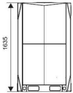
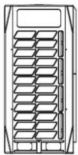
natural_image
Technical line drawing of a multi-panel rack or storage unit (no text or symbols)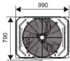
14\~16 HP
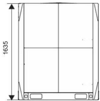
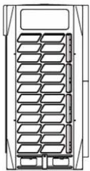
natural_image
Technical line drawing of a multi-panel storage unit or rack system (no text or symbols)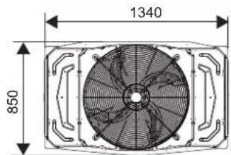
18\~22 HP
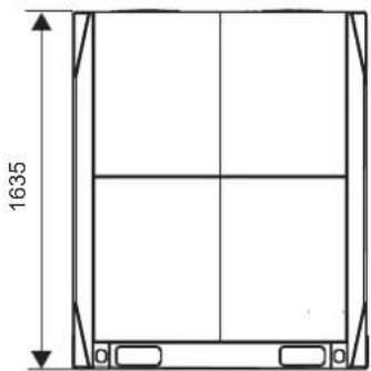
natural_image
Technical line drawing of a rectangular frame with vertical and horizontal divisions, showing dimension 1635 (no text or symbols)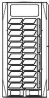
natural_image
Technical line drawing of a mechanical component with multiple slots and a top panel (no text or symbols)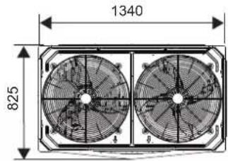
24\~32 HP
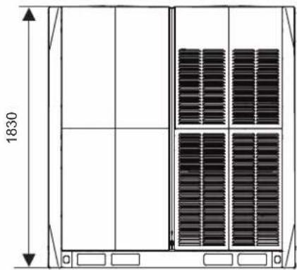
natural_image
Technical line drawing of a rectangular enclosure with vertical supports and internal grating (no text or symbols)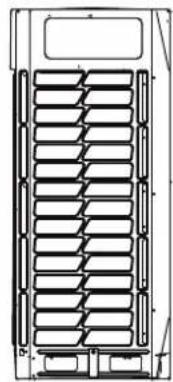
natural_image
Technical line drawing of a mechanical component with multiple parallel grooves and mounting brackets (no text or symbols)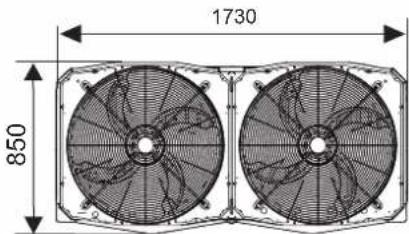
11.2 Maintenance Space: Outdoor Unit
Make sure there is sufficient space around the unit for maintenance work, and the minimum space for air inlet and air outlet is reserved (see below to select a feasible method).

Note
- Ensure enough space for maintenance. The units in the same system must be at the same height.
- Outdoor units must be spaced such that sufficient air may flow through each unit. Sufficient airflow across heat exchangers is essential for outdoor units to function properly.
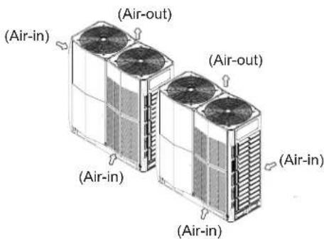
• For single row installation
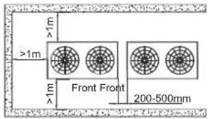
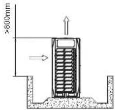
• For multi-row installation
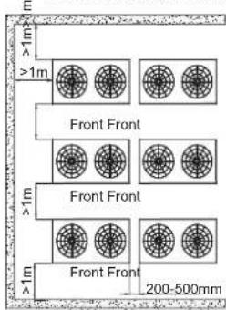
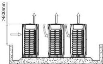
If obstacles are around the outdoor unit, they must be 800mm below the top of the outdoor unit. Otherwise, an mechanical exhaust device must be added.
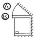
Front view
(one outdoor unit) (one outdoor unit)
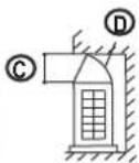
Side view
(one outdoor unit) (one outdoor unit)
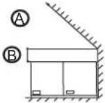
Front view
(two outdoor units
combined)
Front view
(three outdoor
units combined)

45°

300 mm

1000 mm

Airflow deflector
If the particular circumstances of an installation require a unit to be placed closer to a wall. Depending on the height of adjacent walls relative to the height of the units, ducting may be required to ensure proper air discharge. In the situation depicted, the vertical section of ducting should be at least H-h high. If the outdoor unit needs ducting and the static pressure is more than 20Pa, the units should be customized for the corresponding static pressure.
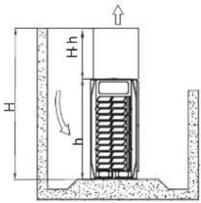
11.3 Component Layout and Refrigerant Circuits
8-12HP
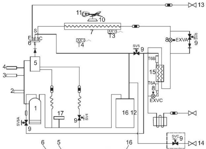
flowchart
graph TD
    A["1"] --> B["2"]
    B --> C["3"]
    C --> D["4"]
    D --> E["5"]
    E --> F["S"]
    F --> G["6"]
    G --> H["7"]
    H --> I["T4"]
    I --> J["8"]
    J --> K["9"]
    K --> L["10"]
    L --> M["11"]
    M --> N["12"]
    N --> O["13"]
    O --> P["14"]
    P --> Q["15"]
    Q --> R["16"]
    R --> S["17"]
    S --> T["18"]
    T --> U["19"]
    U --> V["20"]
    V --> W["21"]
    W --> X["22"]
    X --> Y["23"]
    Y --> Z["24"]
    Z --> AA["25"]
    AA --> AB["26"]
    AB --> AC["27"]
    AC --> AD["28"]
    AD --> AE["29"]
    AE --> AF["30"]
    AF --> AG["31"]
    AG --> AH["32"]
    AH --> AI["33"]
    AI --> AJ["34"]
    AJ --> AK["35"]
    AK --> AL["36"]
    AL --> AM["37"]
    AM --> AN["38"]
    AN --> AO["39"]
    AO --> AP["40"]
    AP --> AQ["41"]
    AQ --> AR["42"]
    AR --> AS["43"]
    AS --> AT["44"]
    AT --> AU["45"]
    AU --> AV["46"]
    AV --> AW["47"]
    AW --> AX["48"]
    AX --> AY["49"]
    AY --> AZ["50"]
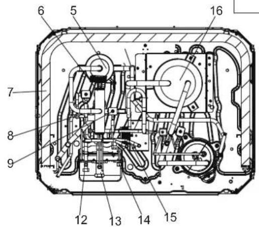

Legend:
-
Compressor
-
Temperature sensor for discharge gas
-
High pressure switch
-
Pressure sensor
-
Oil separator
-
Four-way valve
-
Heat exchanger
-
Electronic Expansion Valve
-
Solenoid valve
-
Motor
-
Fan Blade
-
Stop valve (liquid side)
-
Stop valve (gas side)
-
Detection needle valve
-
Plate heat exchanger
-
Gas-liquid separator
-
Low pressure switch
T3 Condenser temperature sensor
T4 Outdoor temperature sensor
T6A Temperature sensor at plate heat exchanger inlet
T6B Temperature sensor at plate heat exchanger outlet
SV4 Fast oil return value
SV5 Low pressure bypass value
SV6 Liquid bypass value
SV7 Pressure value
SV8 Injection valve value
SVC Refrigerant charging valve (customization option)
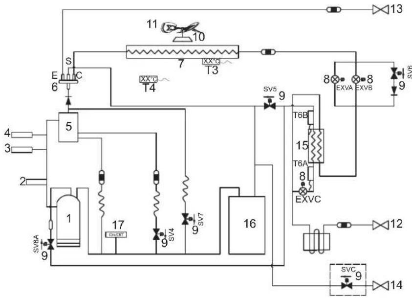
flowchart
graph TD
    A["1"] --> B["2"]
    B --> C["3"]
    C --> D["4"]
    D --> E["5"]
    E --> F["6"]
    F --> G["S"]
    G --> H["C"]
    H --> I["7"]
    I --> J["T3"]
    J --> K["8"]
    K --> L["9"]
    L --> M["10"]
    M --> N["11"]
    N --> O["12"]
    O --> P["13"]
    P --> Q["14"]
    Q --> R["15"]
    R --> S["T6A"]
    S --> T["8"]
    T --> U["EXVC"]
    U --> V["9"]
    V --> W["16"]
    W --> X["T6B"]
    X --> Y["T6C"]
    Y --> Z["SV5"]
    Z --> AA["9"]
    AA --> AB["16"]
    AB --> AC["17"]
    AC --> AD["16"]
    AD --> AE["SV7A"]
    AE --> AF["9"]
    AF --> AG["16"]
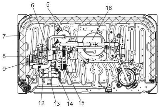
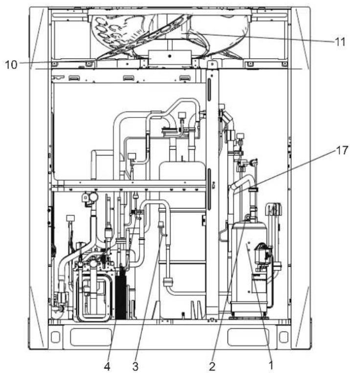
Legend:
-
Compressor
-
Temperature sensor for discharge gas
-
High pressure switch
-
Pressure sensor
-
Oil separator
-
Four-way valve
-
Heat exchanger
-
Electronic Expansion Valve
-
Solenoid valve
-
Motor
-
Fan Blade
-
Stop valve (liquid side)
-
Stop valve (gas side)
-
Detection needle valve
-
Plate heat exchanger
-
Gas-liquid separator
-
Low pressure switch
T3 Condenser temperature sensor
T4 Outdoor temperature sensor
T6A Temperature sensor at plate heat exchanger inlet
T6B Temperature sensor at plate heat exchanger outlet
SV4 Fast oil return value
SV5 Low pressure bypass
SV6 Liquid bypass value
SV7 Pressure value
SV8 Injection valve
SVC Refrigerant charging valve (customization option)
18-22HP
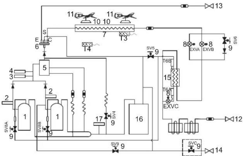
flowchart
graph TD
    A["1"] --> B["2"]
    B --> C["3"]
    C --> D["4"]
    D --> E["5"]
    E --> F["6"]
    F --> G["7"]
    G --> H["8"]
    H --> I["9"]
    I --> J["10"]
    J --> K["11"]
    K --> L["12"]
    L --> M["13"]
    M --> N["14"]
    N --> O["15"]
    O --> P["16"]
    P --> Q["17"]
    Q --> R["T6B"]
    R --> S["T6A"]
    S --> T["EXVC"]
    T --> U["T6C"]
    U --> V["SVC"]
    V --> W["SVC9"]
    W --> X["T6B"]
    X --> Y["T6A"]
    Y --> Z["EXVC"]
    Z --> AA["T6C"]
    AA --> AB["SVC9"]
    AB --> AC["T6B"]
    AC --> AD["T6A"]
    AD --> AE["EXVC"]
    AE --> AF["T6C"]
    AF --> AG["SVC9"]
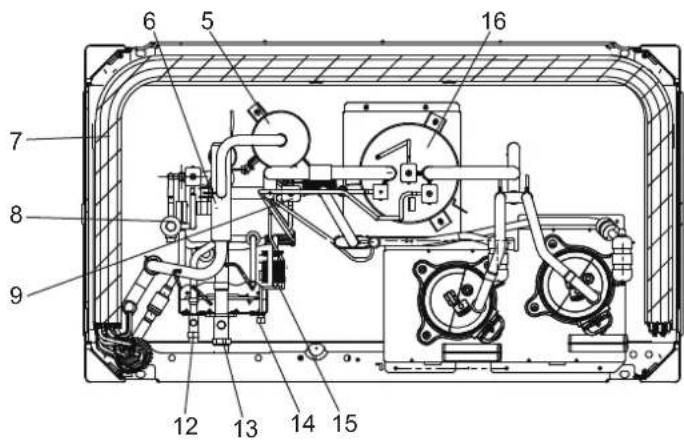
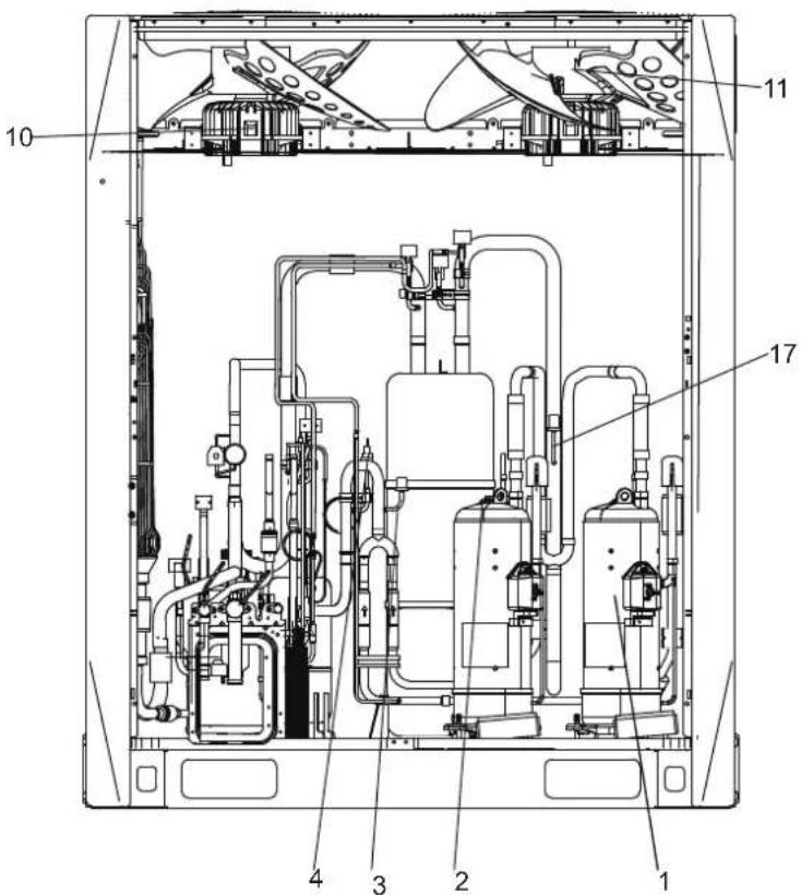
Legend:
- Compressor
- Temperature sensor for discharge gas
- High pressure switch
- Pressure sensor
- Oil separator
- Four-way valve
- Heat exchanger
- Electronic Expansion Valve
- Solenoid valve
- Motor
- Fan Blade
- Stop valve (liquid side)
- Stop valve (gas side)
- Detection needle valve
- Plate heat exchanger
- Gas-liquid separator
- Low pressure switch
T3 Condenser temperature sensor
T4 Outdoor temperature sensor
T6A Temperature sensor at plate heat exchanger inlet
T6B Temperature sensor at plate heat exchanger outlet
SV4 Fast oil return value
SV5 Low Pressure bypass
SV6 Liquid bypass value
SV7 Pressure bypassvalue
SV8A Injection valve A
SV8B Injection valve B
SV9 Pressure unloading valve
SVC Refrigerant charging valve (customization option)
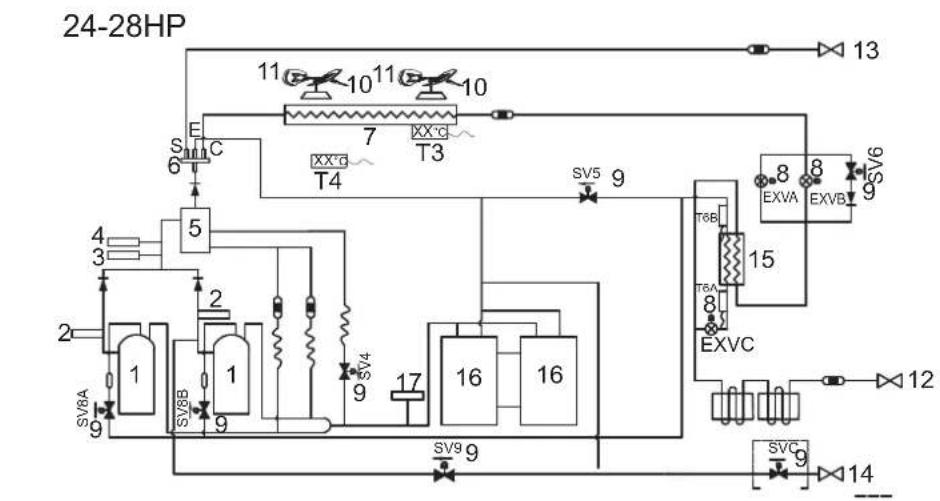
flowchart
graph TD
    A["24-28HP"] --> B["1"]
    A --> C["2"]
    A --> D["3"]
    A --> E["4"]
    A --> F["5"]
    A --> G["6"]
    A --> H["7"]
    A --> I["8"]
    A --> J["9"]
    A --> K["10"]
    A --> L["11"]
    A --> M["12"]
    A --> N["13"]
    A --> O["14"]
    A --> P["15"]
    A --> Q["16"]
    A --> R["17"]
    A --> S["18"]
    A --> T["19"]
    A --> U["20"]
    A --> V["21"]
    A --> W["22"]
    A --> X["23"]
    A --> Y["24"]
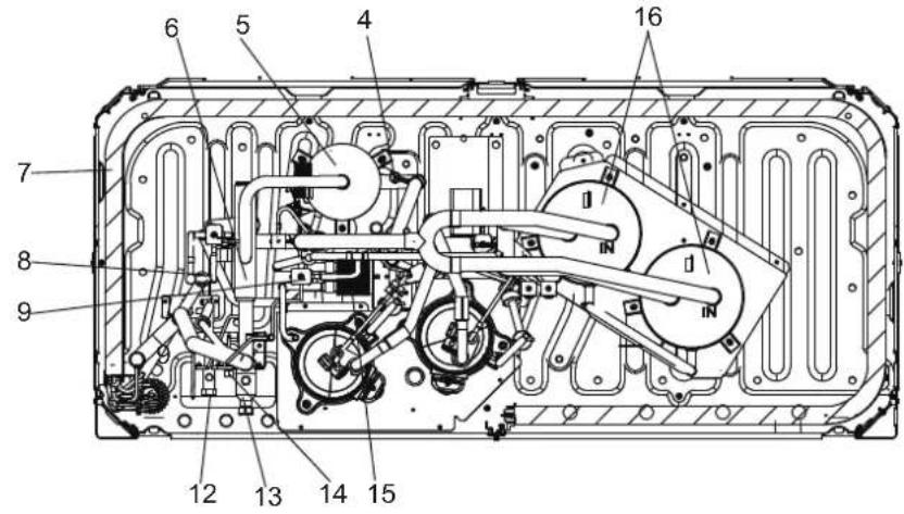
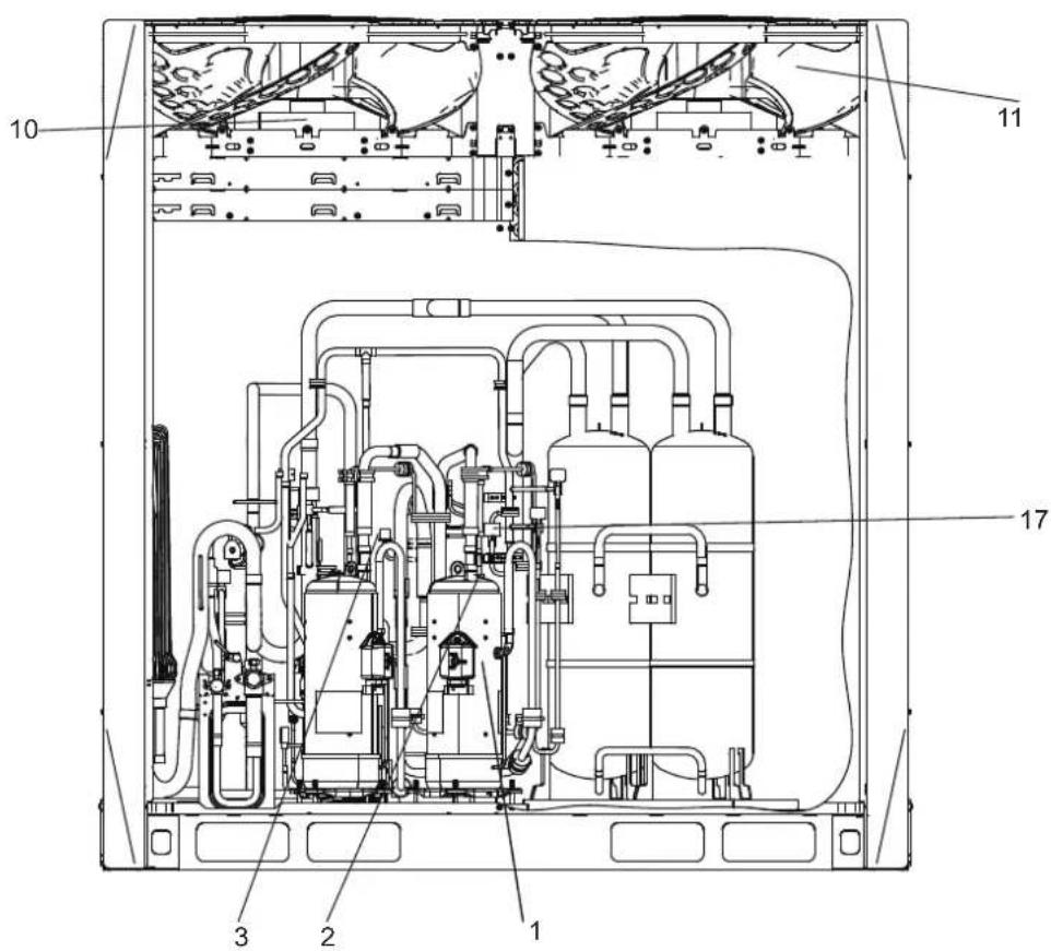
Legend:
- Compressor
- Temperature sensor for discharge gas
- High pressure switch
- Pressure sensor
- Oil separator
- Four-way valve
- Heat exchanger
- Electronic Expansion Valve
- Solenoid valve
- Motor
- Fan Blade
- Stop valve (liquid side)
- Stop valve (gas side)
- Detection needle valve
- Plate heat exchanger
- Gas-liquid separator
- Low pressure switch
T3 Condenser temperature sensor
T4 Outdoor temperature sensor
T6A Temperature sensor at plate heat exchanger inlet
T6B Temperature sensor at plate heat exchanger outlet
SV4 Fast oil returnvalue
SV5 Low pressure bypass
SV6 Liquid bypass value
SV7 Pressure value
SV8A Injection valve A
SV8B Injection valve B
SV9 Pressure unloading valve
SVC Refrigerant charging valve (customization option)
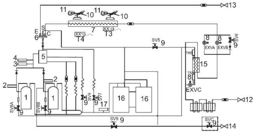
flowchart
graph TD
    A["1"] --> B["2"]
    B --> C["3"]
    C --> D["4"]
    D --> E["5"]
    E --> F["6"]
    F --> G["7"]
    G --> H["8"]
    H --> I["9"]
    I --> J["10"]
    J --> K["11"]
    K --> L["12"]
    L --> M["13"]
    M --> N["14"]
    N --> O["15"]
    O --> P["16"]
    P --> Q["17"]
    Q --> R["18"]
    R --> S["19"]
    S --> T["20"]
    T --> U["21"]
    U --> V["22"]
    V --> W["23"]
    W --> X["24"]
    X --> Y["25"]
    Y --> Z["26"]
    Z --> AA["27"]
    AA --> AB["28"]
    AB --> AC["29"]
    AC --> AD["30"]
    AD --> AE["31"]
    AE --> AF["32"]
    AF --> AG["33"]
    AG --> AH["34"]
    AH --> AI["35"]
    AI --> AJ["36"]
    AJ --> AK["37"]
    AK --> AL["38"]
    AL --> AM["39"]
    AM --> AN["40"]
    AN --> AO["41"]
    AO --> AP["42"]
    AP --> AQ["43"]
    AQ --> AR["44"]
    AR --> AS["45"]
    AS --> AT["46"]
    AT --> AU["47"]
    AU --> AV["48"]
    AV --> AW["49"]
    AW --> AX["50"]
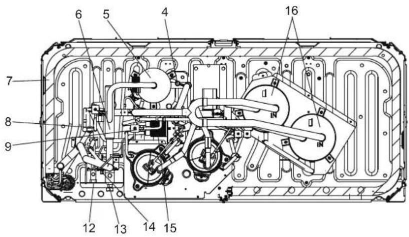

Legend:
- Compressor
- Temperature sensor for discharge gas
- High pressure switch
- Pressure sensor
- Oil separator
- Four-way valve
- Heat exchanger
- Electronic Expansion Valve
-
Solenoid valve
-
Motor
-
Fan Blade
-
Stop valve (liquid side)
-
Stop valve (gas side)
-
Detection needle valve
-
Plate heat exchanger
-
Gas-liquid separator
-
Low pressure switch
T3 Condenser temperature sensor
T4 Outdoor temperature sensor
T6A Temperature sensor at plate heat exchanger inlet
T6B Temperature sensor at plate heat exchanger outlet
SV4 Fast oil return value
SV5 Low pressure bypass
SV6 Liquid bypass value
SV7 Pressure value
SV8A Injection valve A
SV8B Injection valve B
SV9 Pressure unloading valve
SVC Refrigerant charging valve (customization option)
11.4 Fan Performance
The default external static pressure of outdoor units' air outlets is zero. With the steel mesh cover removed the external static pressure is 20Pa.
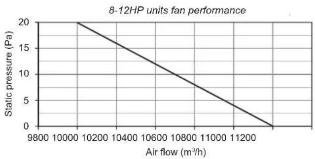
line
| Air flow (m³/h) | Static pressure (Pa) | | --------------- | -------------------- | | 9800 | 20 | | 10000 | 15 | | 10200 | 10 | | 10400 | 5 | | 10600 | 0 | | 10800 | -5 | | 11000 | -10 | | 11200 | -15 | | 11400 | -20 |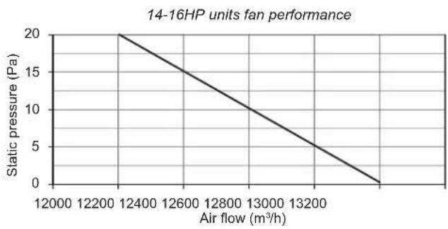
line
| Air flow (m³/h) | Static pressure (Pa) | | --------------- | -------------------- | | 12400 | 20 | | 12600 | 15 | | 12800 | 10 | | 13000 | 5 | | 13200 | 0 |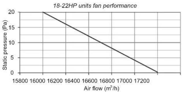
line
| Air flow (m³/h) | Static pressure (Pa) | | --------------- | -------------------- | | 15800 | 20 | | 16000 | 15 | | 16200 | 10 | | 16400 | 5 | | 16600 | 0 | | 16800 | -5 | | 17000 | -10 | | 17200 | -15 | | 17400 | -20 |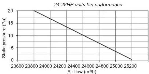
line
| Air flow (m³/h) | Static pressure (Pa) | | --------------- | -------------------- | | 23600 | 20 | | 23800 | 18 | | 24000 | 16 | | 24200 | 14 | | 24400 | 12 | | 24600 | 10 | | 24800 | 8 | | 25000 | 6 | | 25200 | 4 | | 25400 | 2 | | 25600 | 0 |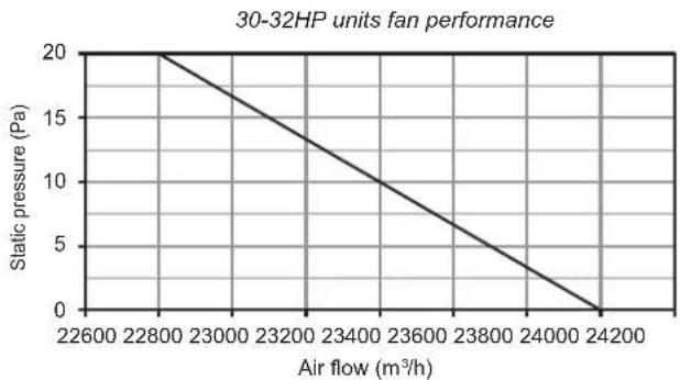
line
| Air flow (m³/h) | Static pressure (Pa) | | --------------- | -------------------- | | 22600 | 20 | | 22800 | 15 | | 23000 | 10 | | 23200 | 5 | | 23400 | 0 | | 23600 | -5 | | 23800 | -10 | | 24000 | -15 | | 24200 | -20 |11.5 Outdoor Unit Ducting
Ducting for 8-12HP
Option A – Transverse ducting
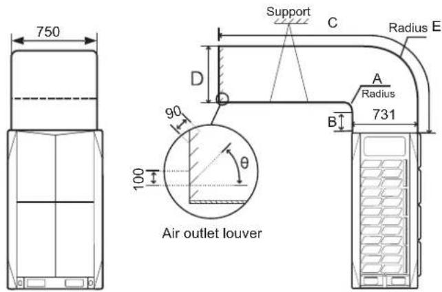
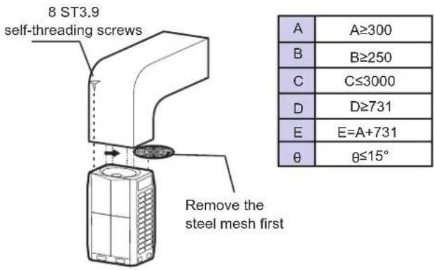
Option B – Longitudinal ducting
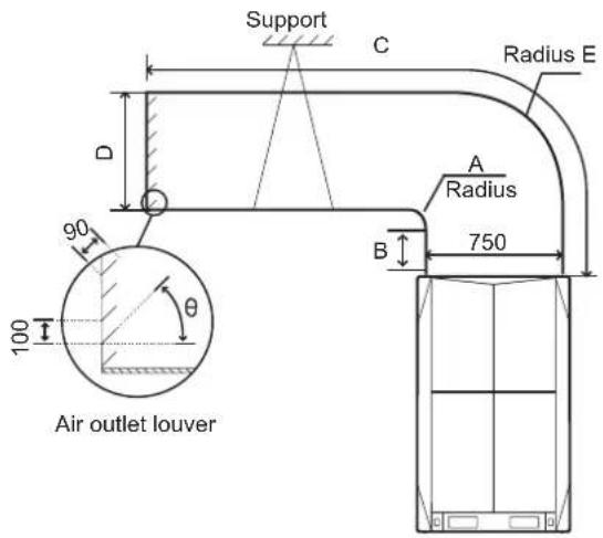
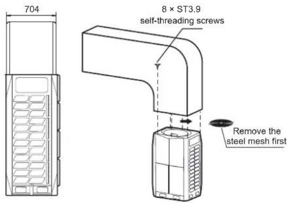
| A | A≥300 |
| B | B≥250 |
| C | C≤3000 |
| D | D≥750 |
| E | E=A+750 |
| θ | θ≤15° |
| Static pressure | Remark |
| 0 Pa | Factory default |
| 0-20 Pa | Remove steel mesh and connect to duct < 3m long |
| Above 20 Pa | Customization option |
Option B – Longitudinal ducting
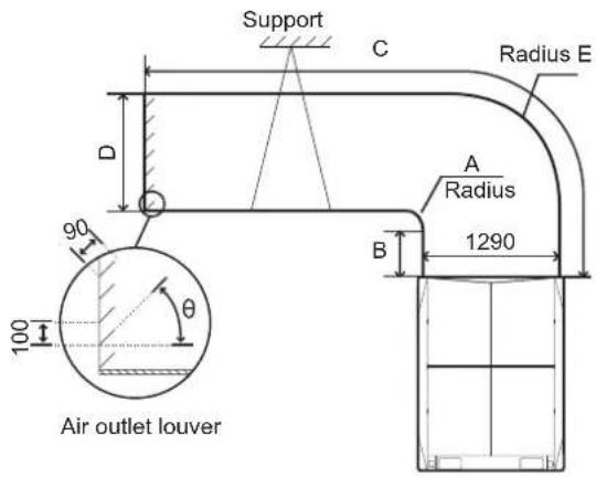
Ducting for 14-16HP
Option A – Transverse ducting
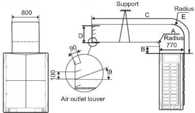
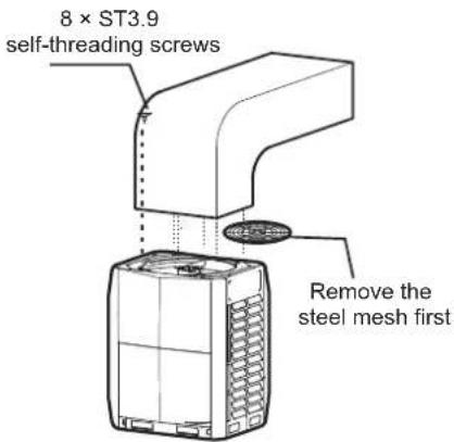
| A | A≥300 |
| B | B≥250 |
| C | C≤3000 |
| D | D≥770 |
| E | E=A+770 |
| θ | θ≤15° |
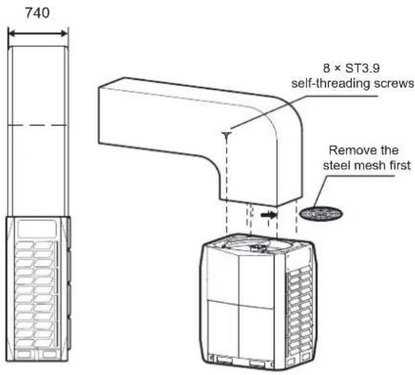
| A | A≥300 |
| B | B≥250 |
| C | C≤3000 |
| D | D≥1290 |
| E | E=A+1290 |
| θ | θ≤15° |
| Static pressure | Remark |
| 0 Pa | Factory default |
| 0-20 Pa | Remove steel mesh and connect to duct < 3m long |
| Above 20 Pa | Customization option |
Ducting for 18-22HP
Option A – Transverse ducting
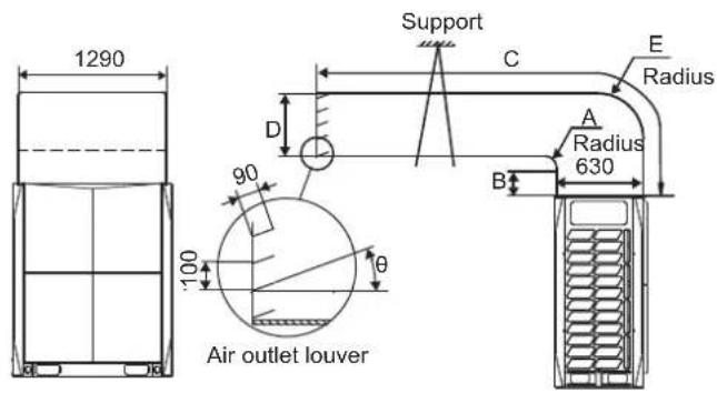
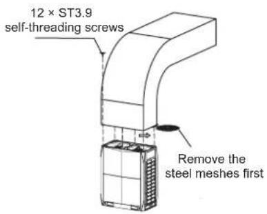
| A | A≥300 |
| B | B≥250 |
| C | C≤3000 |
| D | D≥630 |
| E | E=A+630 |
| θ | θ≤15° |
Option B - Longitudinal ducting
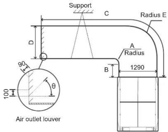
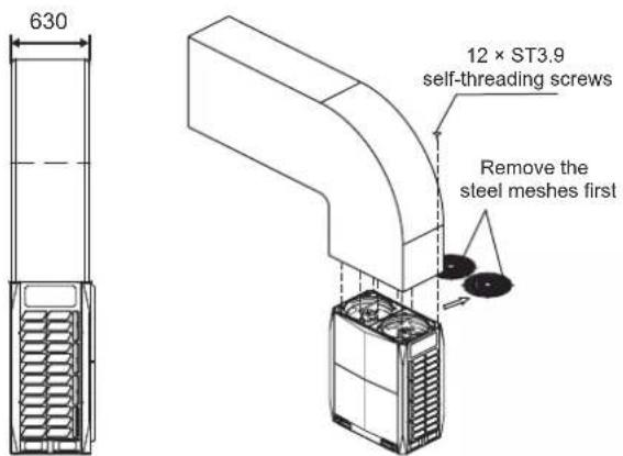
| A | A≥300 |
| B | B≥250 |
| C | C≤3000 |
| D | D≥1290 |
| E | E=A+1290 |
| θ | θ≤15° |
| Static pressure | Remark |
| 0 Pa | Factory default |
| 0-20 Pa | Remove steel mesh and connect to duct < 3m long |
| Above 20 Pa | Customization option |
Ducting for 24-32HP
Transverse ducting only
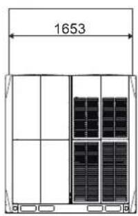
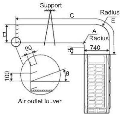
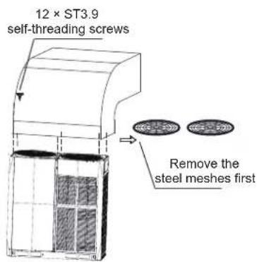
| A | A≥300 |
| B | B≥250 |
| C | C≤3000 |
| D | D≥740 |
| E | E=A+740 |
| θ | θ≤15° |
| Static pressure | Remark |
| 0 Pa | Factory default |
| 0-20 Pa | Remove steel mesh and connect to duct < 3m long |
| Above 20 Pa | Customization option |
HTW
QUALITY COMFORT EVERYWHERE
UNITÉ EXTÉRIEURE
V10
FRANÇAIS
HTW-VO252FI13V10 / HTW-VO280FI16V10 / HTW-VO335FI20V10
HTW-VO400FI23V10 / HTW-VO450FI26V10 / HTW-VO500FI29V10
HTW-VO560FI33V10 / HTW-VO670FI39V10 / HTW-VO730FI43V10
HTW-VO785FI46V10 / HTW-VO850FI50V10 / HTW-VO900FI53V10
NOTE
natural_image
Technical line drawing of a server rack unit with ventilation grilles and doorways (no text or symbols)flowchart
graph TD
    subgraph W3
        A1["Grid (12)"] -->|g1| S
        B1["Grid (22)"] -->|g2| S
        C1["Grid (32)"] -->|g3| S
    end
    subgraph W2
        D1["Grid (140)"] -->|a| E1["L4"]
        F1["Grid (140)"] -->|b| E2["L5"]
        G1["Grid (140)"] -->|c| H1["E"]
        I1["Grid (140)"] -->|d| H2["H"]
        J1["Grid (140)"] -->|e| H3["G"]
        K1["Grid (140)"] -->|f| H4["N5"]
        L1["Grid (140)"] -->|g| H5["N6"]
        M1["Grid (140)"] -->|h| H6["N7"]
        N1["Grid (140)"] -->|i| H7["N9"]
        O1["Grid (140)"] -->|j| H8["N10"]
        P1["Grid (140)"] -->|k| H9["M"]
        Q1["Grid (140)"] -->|l| H10["N11"]
        R1["Grid (140)"] -->|m| H11["N12"]
        S1["Grid (140)"] -->|n| H12["N13"]
        T1["Grid (140)"] -->|o| H13["N14"]
        U1["Grid (140)"] -->|p| H14["N15"]
        V1["Grid (140)"] -->|q| H15["N16"]
        W1["Grid (140)"] -->|r| H16["N17"]
    end
    subgraph W1
        X["Grid (22)"]
        Y["Grid (32)"]
    end
    subgraph W2
        Z["Grid (22)"]
        AA["Grid (32)"]
    end
    subgraph W3
        AB["Grid (22)"]
        AC["Grid (32)"]
    end
    subgraph W3
        AD["Grid (22)"]
        AE["Grid (32)"]
    end
    subgraph W3
        AF["Grid (22)"]
        AG["Grid (32)"]
    end
    subgraph W3
        AH["Grid (22)"]
        AI["Grid (32)"]
    end
    subgraph W3
        AJ["Grid (22)"]
        AK["Grid (32)"]
    end
    subgraph W3
        AL["Grid (22)"]
        AM["Grid (32)"]
    end
    subgraph W3
        AN["Grid (22)"]
        AO["Grid (32)"]
    end
    subgraph W3
        AP["Grid (22)"]
        AQ["Grid (32)"]
    end
    subgraph W3
        AR["Grid (22)"]
        AS["Grid (32)"]
    end
    subgraph W3
        AT["Grid (22)"]
        AU["Grid (32)"]
    end
    subgraph W3
        AV["Grid (22)"]
        AW["Grid (32)"]
    end
    subgraph W3
        AX["Grid (22)"]
        AY["Grid (32)"]
    end
    subgraph W3
        AZ["Grid (22)"]
        BA["Grid (32)"]
    end
    subgraph W3
        BB["Grid (22)"]
        BC["Grid (32)"]
    end
    subgraph W3
        BD["Grid (22)"]
        BE["Grid (32)"]
    end
    subgraph W3
        BF["Grid (22)"]
        BG["Grid (32)"]
    end
    subgraph W3
        BH["Grid (22)"]
        BI["Grid (32)"]
    end
    subgraph W3
        BJ["Grid (22)"]
        BK["Grid (32)"]
    end
    subgraph W3
        BL["Grid (22)"]
        BM["Grid (32)"]
    end
    subgraph W3
        BN["Grid (22)"]
        BO["Grid (32)"]
    end
    subgraph W3
        BP["Grid (22)"]
        BQ["Grid (32)"]
    end
    subgraph W3
        BR["Grid (22)"]
        BS["Grid (32)"]
    end
    subgraph W3
        BT["Grid (22)"]
        BU["Grid (32)"]
    end
    subgraph W3
        BV["Grid (22)"]
        BW["Grid (32)"]
    end
    subgraph W3
        BX["Grid (22)"]
        BY["Grid (32)"]
    end
    subgraph W3
        BZ["Grid (22)"]
        CA["Grid (32)"]
    end
    subgraph W3
        CB["Grid (22)"]
        CD["Grid (32)"]
    end
    subgraph W3
        CE["Grid (22)"]
        CF["Grid (32)"]
    end
    subgraph W3
        GD["Grid (22)"]
        DH["Grid (32)"]
    end
    subgraph W3
        DI["Grid (22)"]
        DJ["Grid (32)"]
    end
    subgraph W3
        DK["Grid (22)"]
        DL["Grid (32)"]
    end
    subgraph W3
        DV["Grid (22)"]
        DW["Grid (32)"]
    end
    subgraph W3
        DX["Grid (22)"]
        DXB["Grid (32)"]
    end
Illustr. 4.2
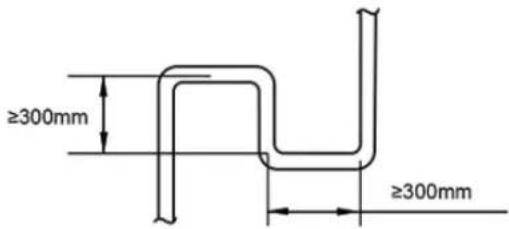
Illustr. 4.3
natural_image
Line drawing of three identical air conditioning units with heat sinks and ventilation grilles (no text or symbols)√ Correct
Illustr. 4.4
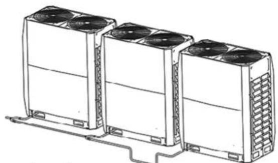
natural_image
Line drawing of three identical air conditioning units with cooling fans and ventilation grilles, connected by a cable (no text or symbols)× Incorrect
Illustr. 4.5
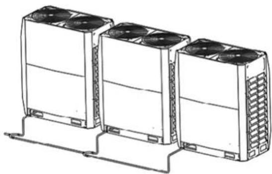
natural_image
Line drawing of three industrial air conditioning units with cooling fans and ventilation grilles (no text or symbols)√ Correct
Illustr. 4.6
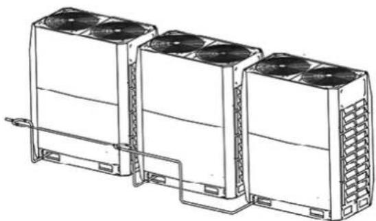
natural_image
Line drawing of three industrial cooling units with fans and cooling fins, connected by piping (no text or symbols)× Incorrect
Illustr. 4.7

Remarque
Illustr. 5.2
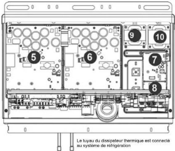
natural_image
Diagram of a mechanical or electrical component with tubing and a valve, no visible text or symbols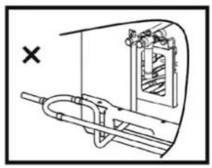
natural_image
Technical diagram of a mechanical device with internal components and directional arrows (no text or labels)
natural_image
Simple line drawing of a mechanical assembly with a bracket and connecting rod (no text or symbols)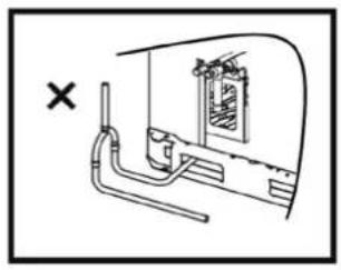
natural_image
Diagram of a pipe system with a window and a cross mark, no text or symbols presentIllustr. 5.9
5.4.6 Soudure
Illustr. 5.13
flowchart
graph LR
    A --> B
    B --> C
    C --> D
    D --> E
    E --> F
    F --> G
    G --> H
    H --> I
    I --> J
    J --> K
    K --> L
    L --> M
    M --> N
    N --> O
    O --> P
    P --> Q
    Q --> R
    R --> S
    S --> T
    T --> U
    U --> V
    V --> W
    W --> X
    X --> Y
    Y --> Z
    Z --> A
Illustr. 5.16
Illustr. 5.23
Illustr. 5.24
Connexions de communication
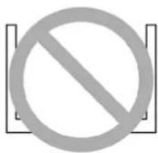
flowchart
graph TD
    A["ODU"] --> B["IDU"]
    A --> C["IDU"]
    A --> D["IDU"]
Illustr. 5.26
natural_image
Diagram of an electronic device rear panel with internal circuit board and cable, no text or symbols presentIllustr. 5.28
natural_image
Technical line drawing of a mechanical assembly with bolts and wires (no text or symbols)Illustr. 5.30
natural_image
Technical line drawing of a mechanical assembly with bolts and tubing (no text or symbols)Illustr. 5.31
natural_image
Technical line drawing of a multi-panel rack or storage unit (no text or symbols)
14\~16 HP
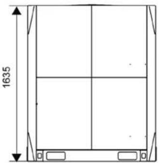
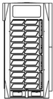
natural_image
Technical line drawing of a multi-panel storage unit or rack structure (no text or symbols)
18\~22 HP
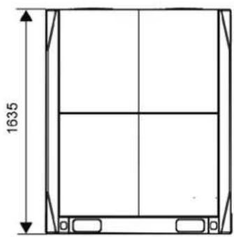
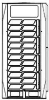
natural_image
Technical line drawing of a multi-panel rack or storage unit (no text or symbols)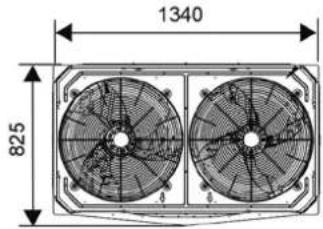
24\~32 HP
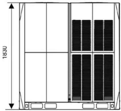
natural_image
Technical line drawing of a multi-panel storage unit with vertical dimensions (1830 and height), no text or symbols present.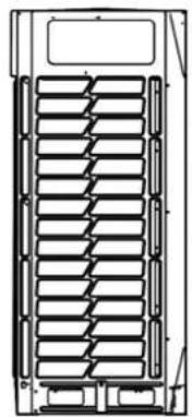
natural_image
Technical line drawing of a mechanical component with internal grid structure (no text or symbols)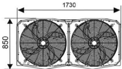
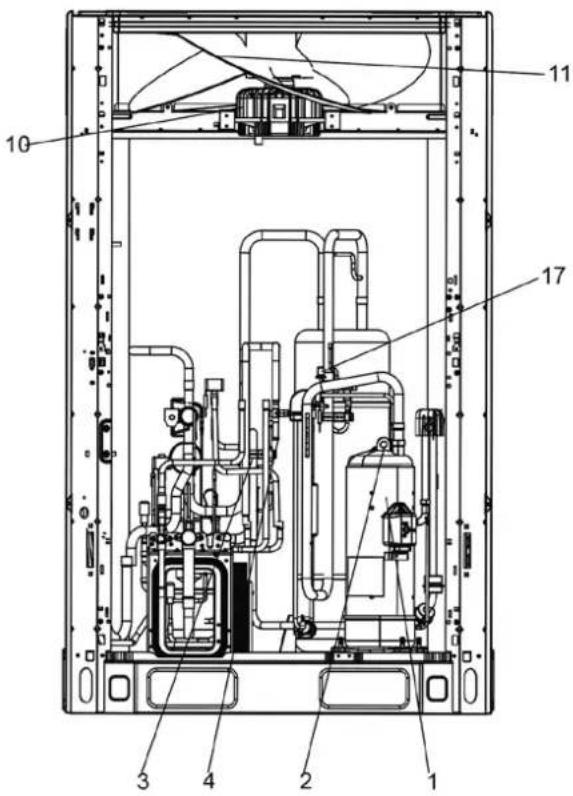
Légende:
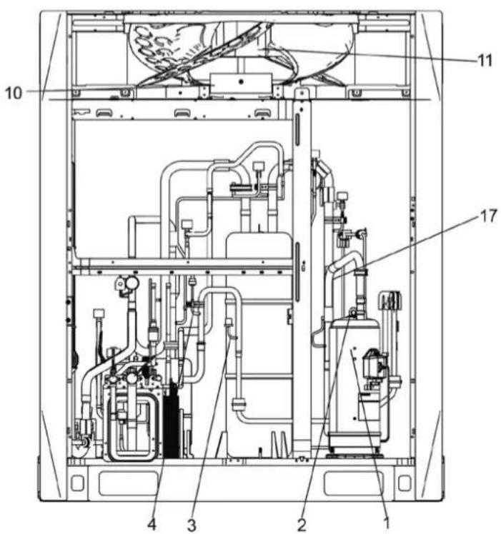
Légende:

Légende:
Légende:
30-32HP
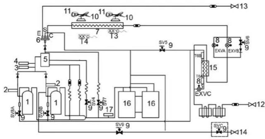
flowchart
graph TD
    A["1"] --> B["2"]
    B --> C["3"]
    C --> D["4"]
    D --> E["5"]
    E --> F["6"]
    F --> G["7"]
    G --> H["8"]
    H --> I["9"]
    I --> J["10"]
    J --> K["11"]
    K --> L["12"]
    L --> M["13"]
    M --> N["14"]
    N --> O["15"]
    O --> P["16"]
    P --> Q["17"]
    Q --> R["18"]
    R --> S["19"]
    S --> T["20"]
    T --> U["21"]
    U --> V["22"]
    V --> W["23"]
    W --> X["24"]
    X --> Y["25"]
    Y --> Z["26"]
    Z --> AA["27"]
    AA --> AB["28"]
    AB --> AC["29"]
    AC --> AD["30"]
    AD --> AE["31"]
    AE --> AF["32"]
    AF --> AG["33"]
    AG --> AH["34"]
    AH --> AI["35"]
    AI --> AJ["36"]
    AJ --> AK["37"]
    AK --> AL["38"]
    AL --> AM["39"]
    AM --> AN["40"]
    AN --> AO["41"]
    AO --> AP["42"]
    AP --> AQ["43"]
    AQ --> AR["44"]
    AR --> AS["45"]
    AS --> AT["46"]
    AT --> AU["47"]
    AU --> AV["48"]
    AV --> AW["49"]
    AW --> AX["50"]
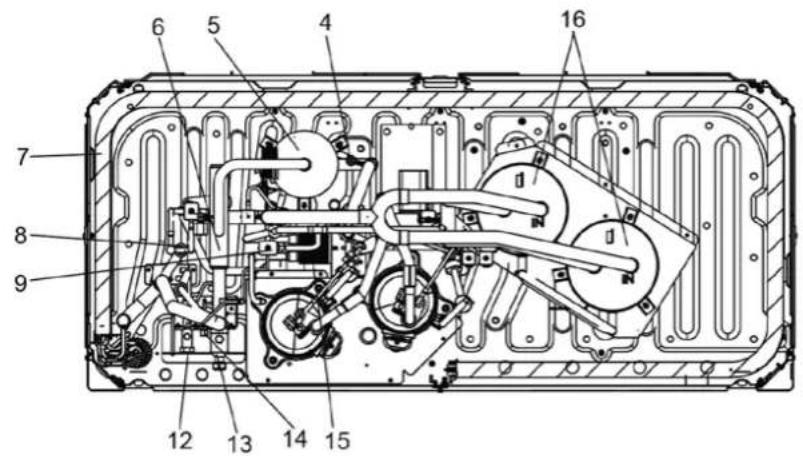
Légende:
1. Compresseur
| A | A≥300 |
| B | B≥250 |
| C | C≤3000 |
| D | D≥731 |
| E | E=A+731 |
| θθ≤15° | |
HTW-VO252FI13V10 / HTW-VO280FI16V10 / HTW-VO335FI20V10
HTW-VO400FI23V10 / HTW-VO450FI26V10 / HTW-VO500FI29V10
HTW-VO560FI33V10 / HTW-VO670FI39V10 / HTW-VO730FI43V10
HTW-VO785FI46V10 / HTW-VO850FI50V10 / HTW-VO900FI53V10
NOTA
natural_image
Technical line drawing of a multi-chamber HVAC unit with grid patterns and ventilation slots (no text or symbols)Figura 4.3
natural_image
Line drawing of three identical air conditioning units with heat sinks and ventilation grilles (no text or symbols)√ Correto
Figura 4.4
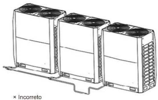
natural_image
Line drawing of three air conditioning units with cooling fans, mounted on a base (no text or symbols)Figura 4.5
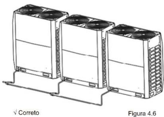
natural_image
Line drawing of three identical air conditioning units with cooling fans, labeled 'Correto' and 'Figura 4.6' (no text on devices)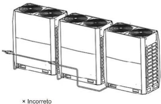
natural_image
Line drawing of three identical air conditioning units with cooling fans, connected by a piping line (no text or symbols on the devices themselves)Figura 4.7

Nota
Figura 5.2

natural_image
Diagram of a mechanical or electrical component with tubing and a valve, no text or symbols present
natural_image
Technical diagram of a mechanical device with internal components and directional arrows (no text or labels)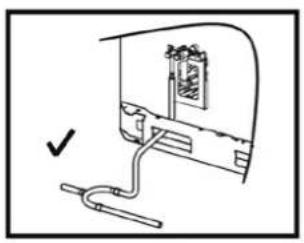
natural_image
Simple line drawing of a device with a cable and a bracket, no text or symbols present
natural_image
Diagram of a vehicle interior with pipes and a window, no text or symbols presentFigura 5.9
5.4.6 Soldagem
Figura 5.13
Figura 5.23
flowchart
graph TD
    subgraph K1
        K1 --> K2
        K2 --> E
        E --> O
        O --> A
        A --> E
    end
    subgraph K2
        K2 --> X
        X --> Y
        Y --> E
        E --> P
        P --> Q
        Q --> E
    end
    subgraph K3
        K3 --> H1
        H1 --> H2
        H2 --> E
    end
    subgraph K4
        K4 --> H1
        H1 --> H2
        H2 --> E
    end
Figura 5.24

natural_image
Diagram of an internal network device with ports and connectors, showing a cable routing from the top panel (no text or labels)Figura 5.28
natural_image
Technical line drawing of a mechanical assembly with bolts and wires (no text or symbols)Figura 5.30
natural_image
Technical diagram of a mechanical assembly with bolts and tubing (no text or symbols)Figura 5.31
natural_image
Technical line drawing of a multi-panel rack or storage unit (no text or symbols)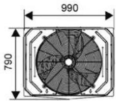
14\~16 HP


natural_image
Technical line drawing of a multi-panel rack or storage unit (no text or symbols)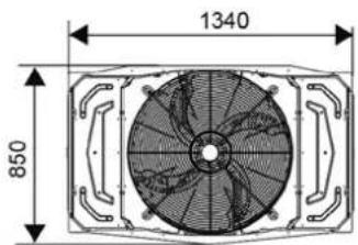
18\~22 CV

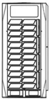
natural_image
Technical line drawing of a multi-panel rack or storage unit (no text or symbols)
24\~32 HP
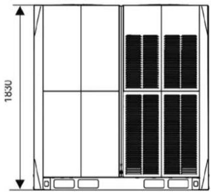
natural_image
Technical line drawing of a cabinet or storage unit with vertical panel layout and dimension label (1830), no readable text or symbols beyond measurement markers.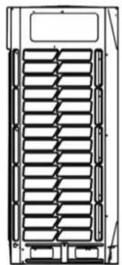
natural_image
Technical line drawing of a mechanical component with internal ribs and mounting brackets (no text or symbols)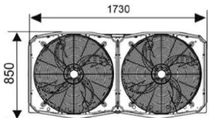
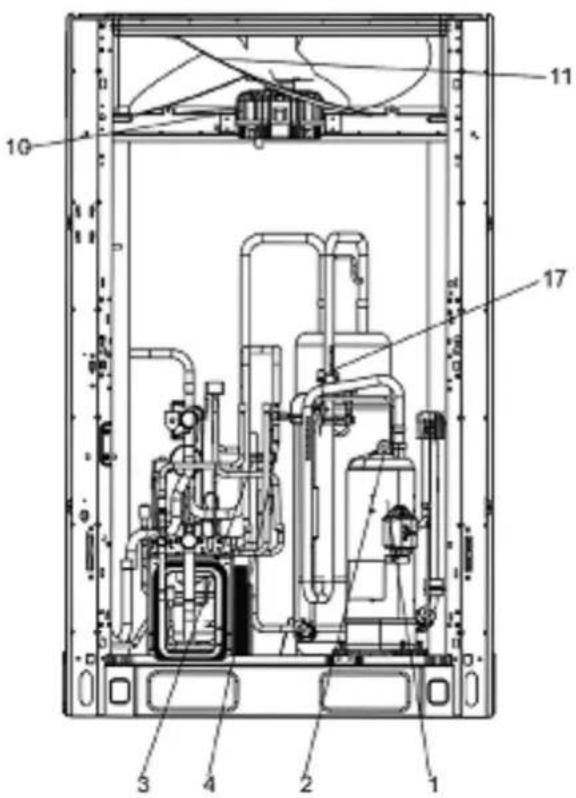
Legenda:
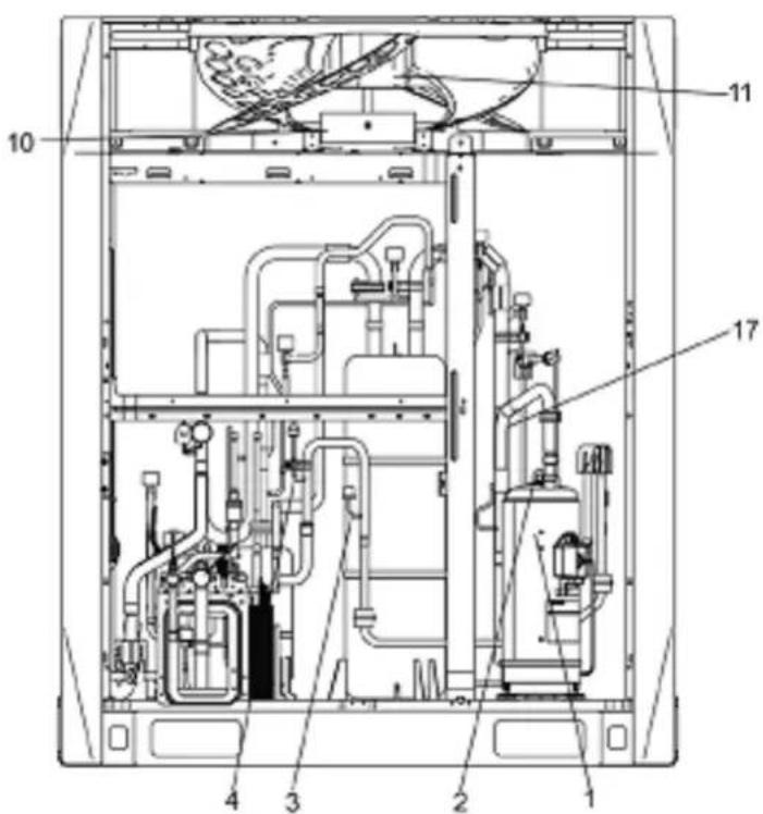
Legenda:
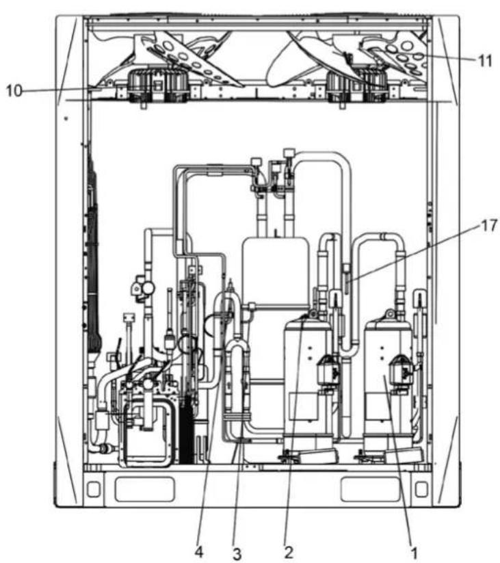
Legenda:
Legenda:
30-32CV
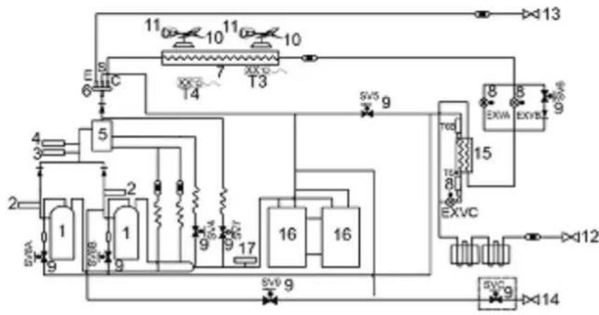
flowchart
graph TD
    A["1"] --> B["2"]
    B --> C["3"]
    C --> D["4"]
    D --> E["5"]
    E --> F["6"]
    F --> G["7"]
    G --> H["8"]
    H --> I["9"]
    I --> J["10"]
    J --> K["11"]
    K --> L["12"]
    L --> M["13"]
    M --> N["14"]
    N --> O["15"]
    O --> P["16"]
    P --> Q["17"]
    Q --> R["18"]
    R --> S["19"]
    S --> T["20"]
    T --> U["21"]
    U --> V["22"]
    V --> W["23"]
    W --> X["24"]
    X --> Y["25"]
    Y --> Z["26"]
    Z --> AA["27"]
    AA --> AB["28"]
    AB --> AC["29"]
    AC --> AD["30"]
    AD --> AE["31"]
    AE --> AF["32"]
    AF --> AG["33"]
    AG --> AH["34"]
    AH --> AI["35"]
    AI --> AJ["36"]
    AJ --> AK["37"]
    AK --> AL["38"]
    AL --> AM["39"]
    AM --> AN["40"]
    AN --> AO["41"]
    AO --> AP["42"]
    AP --> AQ["43"]
    AQ --> AR["44"]
    AR --> AS["45"]
    AS --> AT["46"]
    AT --> AU["47"]
    AU --> AV["48"]
    AV --> AW["49"]
    AW --> AX["50"]
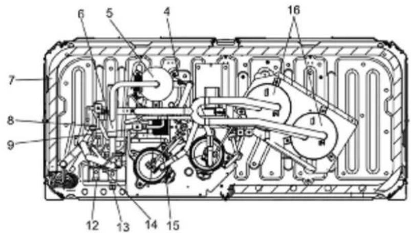
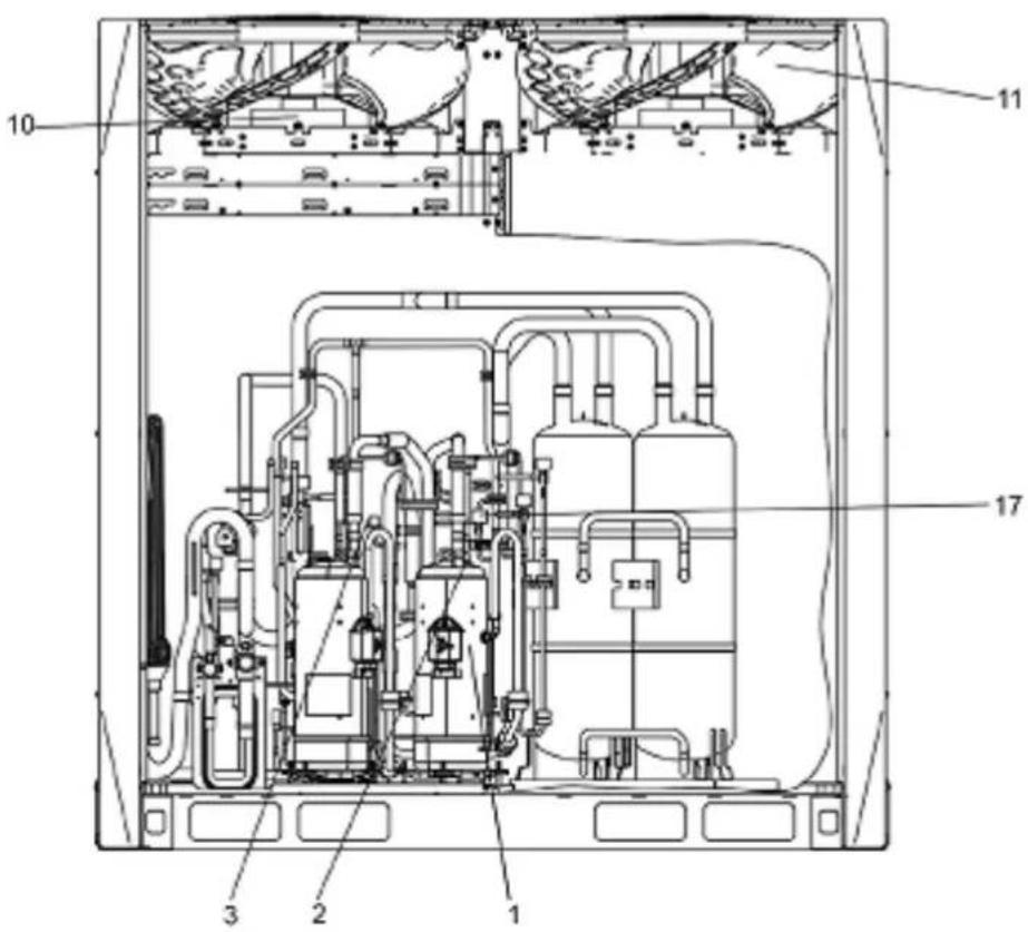
Legenda:
HTW-VO252FI13V10 / HTW-VO280FI16V10 / HTW-VO335FI20V10
HTW-VO400FI23V10 / HTW-VO450FI26V10 / HTW-VO500FI29V10
HTW-VO560FI33V10 / HTW-VO670FI39V10 / HTW-VO730FI43V10
HTW-VO785FI46V10 / HTW-VO850FI50V10 / HTW-VO900FI53V10
NOTA
- The appliance shall be installed in accordance with national wiring regulations.
- If the supply cord is damaged, it must be replaced by the manufacturer or its service agent or a similarly qualified person in order to avoid a hazard.
- An all-pole disconnection switch having a contact separation of at least 3mm in all poles should be connected in fixed wiring.
- The dimensions of the space necessary for correct installation of the appliance including the minimum permissible distances to adjacent structures.
- The temperature of refrigerant circuit will be high, please keep the interconnection cable away from the copper tube

Nota
natural_image
Technical line drawing of a server rack unit with grid patterns and ventilation slots (no text or symbols)Fig. 4.3
natural_image
Line drawing of three identical air conditioning units with cooling fans and ventilation grilles, labeled 'Corretto' at the bottom (no other text or symbols)Fig. 4.4
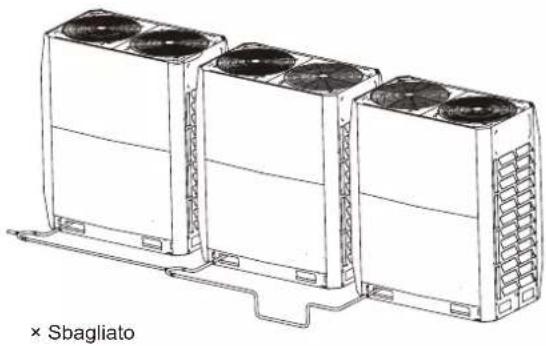
natural_image
Line drawing of three identical air conditioning units with cooling fans and ventilation slots, connected by a support structure (no text or symbols)Fig. 4.5
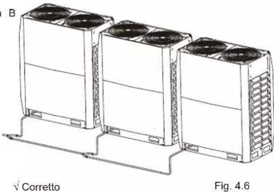
natural_image
Technical line drawing of three air conditioning units with cooling fans, mounted on a base frame (no text or symbols)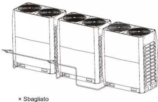
natural_image
Line drawing of three industrial air conditioning units connected by tubing, labeled '× Sbagliato' (no other text or symbols)Fig. 4.7
Nota
Fig. 5.2
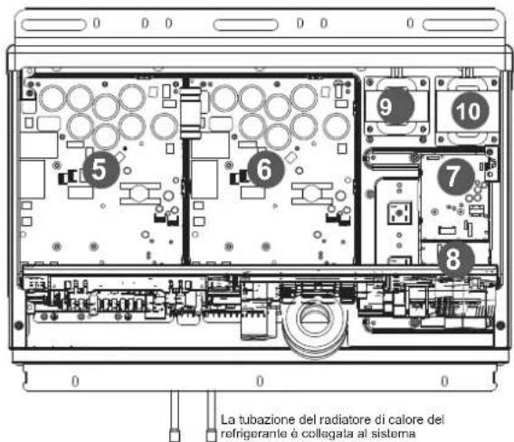
natural_image
Technical diagram showing a mechanical assembly with pipes and a housing component (no text or symbols)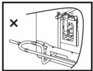
natural_image
Technical diagram of a mechanical assembly with no visible text or symbols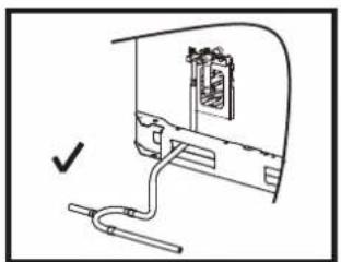
natural_image
Simple line drawing of a device with a cable and connector, no text or symbols present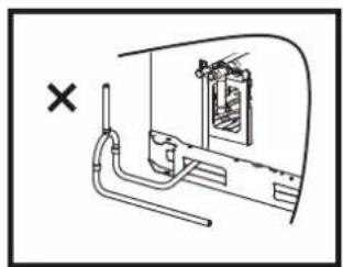
natural_image
Diagram of a piping system with a cross mark and a window, no text or symbols presentFig. 5.9
5.4.6 Brasatura
Fig. 5.13
Result: Valve is now closed.
Direction to close:
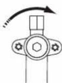
Fig. 5.14
To remove dust, other particles and moisture, which could cause compressor malfunction if not flushed out before the system is run, the refrigerant piping should be flushed using nitrogen. Pipe flushing should be performed once the piping connections have been completed with the exception of the final connections to the indoor units. That is, flushing should be performed once the outdoor units have been connected but before the indoor units are connected.

Attenzione
Fig. 5.24
flowchart
graph TD
    subgraph ODU (Master)
        A["PQ E H1 H2 E"]
    end
    subgraph ODU (Schiava)
        B["PQ E H1 H2 E"]
    end
    subgraph IDU
        C["PQ E"]
    end
    subgraph IDU IDU
        D["PQ E"]
        E["PQ E"]
    end
    A --> F["⊕"]
    B --> G["⊕"]
    C --> H["⊕"]
    D --> I["⊕"]
    E --> J["⊕"]
    F --> K["⊕"]
    G --> L["⊕"]
    H --> M["⊕"]
    I --> N["⊕"]
    J --> O["⊕"]
    K --> P["⊕"]
    L --> Q["⊕"]
    M --> R["⊕"]
    N --> S["⊕"]
    O --> T["⊕"]
    P --> U["⊕"]
    Q --> V["⊕"]
    R --> W["⊕"]
    S --> X["⊕"]
    T --> Y["⊕"]
    U --> Z["⊕"]
    V --> AA["⊕"]
    W --> AB["⊕"]
    X --> AC["⊕"]
    Y --> AD["⊕"]
    Z --> AE["⊕"]
natural_image
Technical line drawing of a computer setup with an open rear panel and cable, showing internal components and connectors (no text or labels)Fig. 5.28
natural_image
Technical line drawing of a mechanical assembly with bolts and wires (no text or symbols)Fig. 5.30
natural_image
Technical line drawing of a mechanical assembly with bolts and tubing (no text or symbols)Fig. 5.31
Then, use 3 pieces of M4*30mm screws to secure the upper cover. At the same time, be careful not to screw it too tight. If you use excessive force to twist to the end, you may destroy the protection layer of the power cable.

Nota
natural_image
Technical line drawing of a rectangular frame with vertical dimensions labeled 1635 (no text or symbols beyond measurement)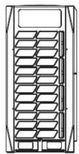
natural_image
Technical line drawing of a multi-panel rack or storage unit (no text or symbols)
18\~22 HP
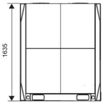
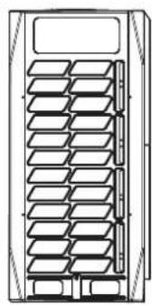
natural_image
Technical line drawing of a multi-tiered storage unit or rack system (no text or symbols)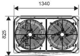
14\~16 HP
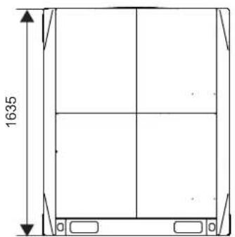
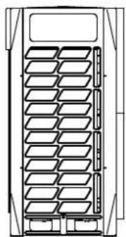
natural_image
Technical line drawing of a multi-level storage or rack system (no text or symbols)24\~32 HP
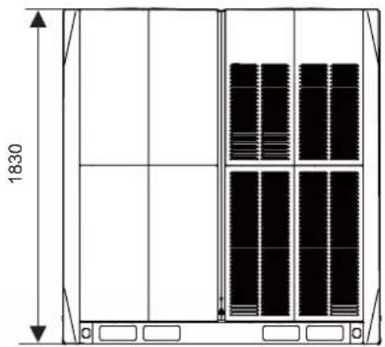
natural_image
Technical line drawing of a cabinet or enclosure with vertical panel layout and dimension label (1830), no readable text or symbols present.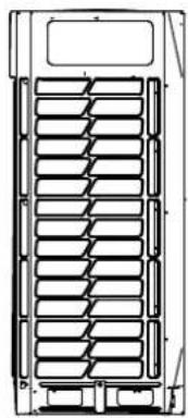
natural_image
Technical line drawing of a multi-layered storage or rack system (no text or symbols)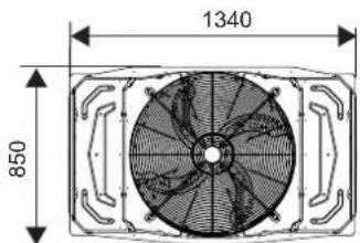
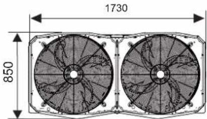

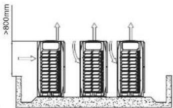
Leggenda:

Leggenda:
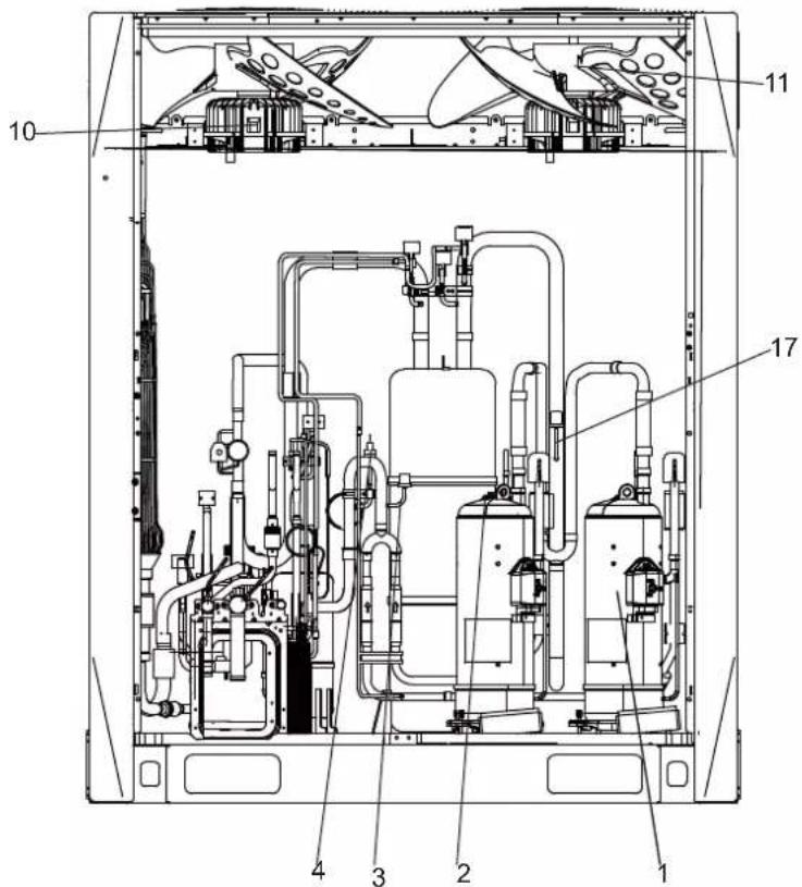
Leggenda:
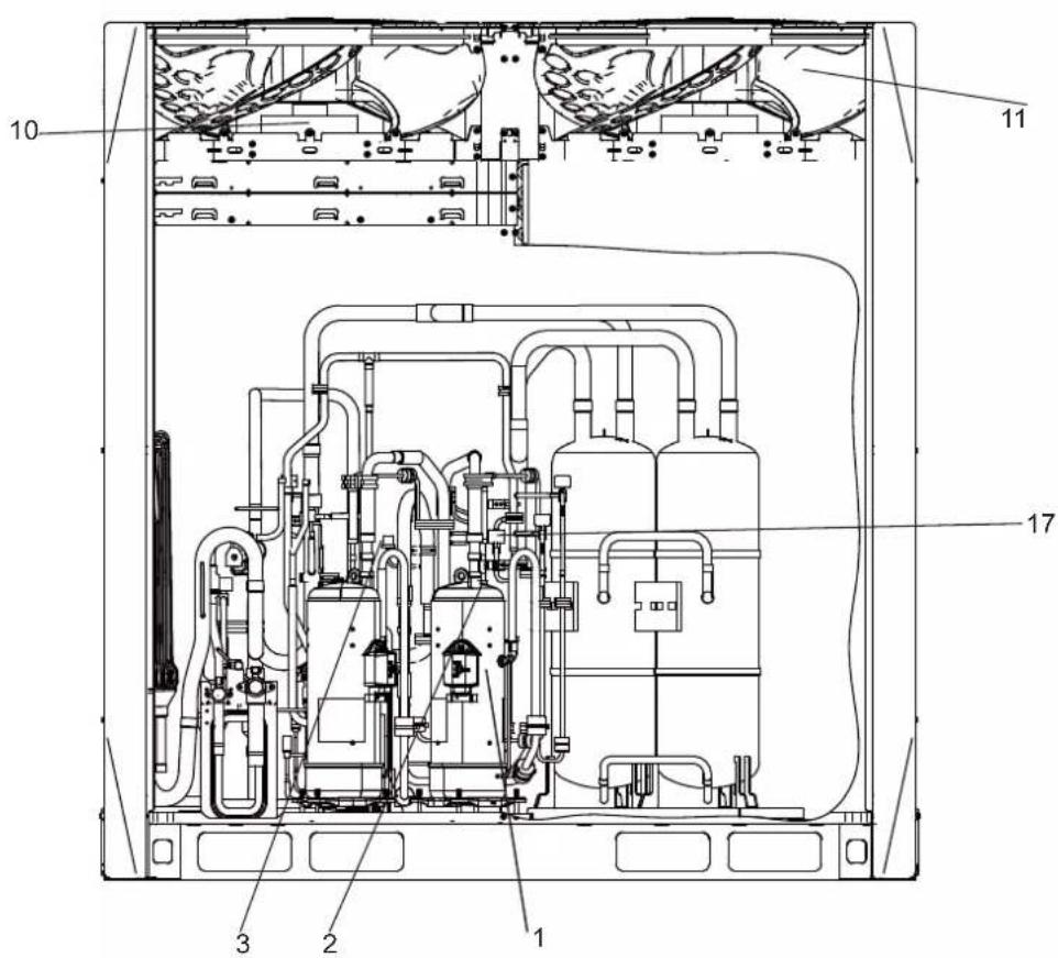
Leggenda:

Leggenda:
info@htwspain.com - www.htwspain.com
FRANCE
info@htwfrance.com
PORTUGAL
info@htw.pt
ITALIA
info.it@htwspain.com
IMPORTANT INFORMATION FOR CORRECT DISPOSAL OF THE PRODUCT IN ACCORDANCE WITH EC DIRECTIVE 2002/96/EC. At the end of its working life, the product must not be disposed of as urban waste. It must be taken to a special local authority deifferentiated waste collection centre or to a dealer providing this service. Disposing of a household appliance separately avoids possible negative consequences for the environment and health deriving from inappropriate disposal and enables the constituent materials to be recovered to obtain significant savings in energy and resources. As a reminder of the need to dispose of household appliances separately, the product is marked with a crossed-outwheeled dustbin.
AVERTISSEMENTS POUR L'ÉLIMINATION CORRECTE DU PRODUIT AUX TERMES DE LA DIRECTIVE 2002/96 / CE.