DigiFlex MA4000D - Multimeter CHAUVIN ARNOUX - Free user manual and instructions
Find the device manual for free DigiFlex MA4000D CHAUVIN ARNOUX in PDF.


User questions about DigiFlex MA4000D CHAUVIN ARNOUX
0 question about this device. Answer the ones you know or ask your own.
Ask a new question about this device
Download the instructions for your Multimeter in PDF format for free! Find your manual DigiFlex MA4000D - CHAUVIN ARNOUX and take your electronic device back in hand. On this page are published all the documents necessary for the use of your device. DigiFlex MA4000D by CHAUVIN ARNOUX.
USER MANUAL DigiFlex MA4000D CHAUVIN ARNOUX
■ MESUREUR FLEXIBLE DE COURANT
■ FLEXIBLE CURRENT METER
■ FLEXIBLE STROMwANDLER
■ MISURATORE FLESSIBILE DI CORRENTE
■ MEDIDOR DE CORRIENTE FLExIBLE
DigiFlex
MA4000D
text_image
4000A MAX 3999A DigiFlex AC-9000 MA 4000D CURRENT METER HOLD MAX (>25)FRANÇAIS
ENGLISH
DEUTSCH
ITALIANO
ESPAÑOL
natural_image
Line drawing of a medical or laboratory device with no visible text, numbers, or symbols.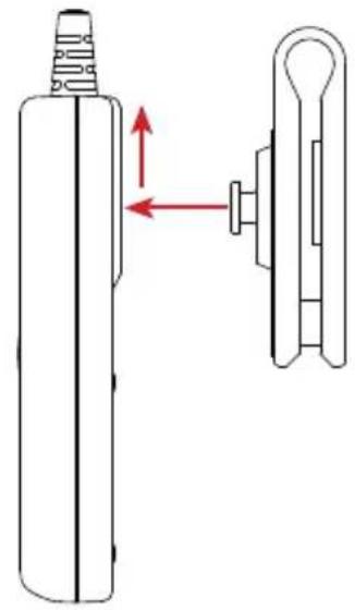
natural_image
Technical line drawing of a mechanical component with a cylindrical body and attached bracket, showing directional arrows (no text or symbols)natural_image
Illustration of a wall-mounted device connected to a circular knob and a ring, with no visible text or symbols.natural_image
Diagram of a mechanical device with a red ring attached to a gray beam, labeled 'à' (no text or symbols on the device itself)2. MESURE DE COURANT
2.1. PRINCIPE DE MESURE
text_image
Diagram illustrating a hand pointing to a medical device with a red circular component, followed by a transformation arrow.natural_image
Simple line drawing of a bone joint with a curved ring and connecting rod (no text or symbols)text_image
HOLD 23.5 I_Atext_image
MAX 26.89AThank you for purchasing a DigiFLEX MA4000D current meter with flexible sensor. For best results from your instrument:
- read this user's manual carefully,
■ comply with the precautions for use.

WARNING, risk of DANGER! The operator must refer to these instructions whenever this danger symbol appears.

Equipment protected by double insulation.

Must not be applied to or removed from bare conductors at dangerous voltages. Type B current sensor as per IEC 61010-2-032.

Battery.

The CE marking indicates conformity with European directives, in particular LVD and EMC.

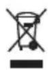
The rubbish bin with a line through it indicates that, in the European Union, the product must undergo selective disposal in compliance with Directive WEEE 2002/96/EC. This equipment must not be treated as household waste.
Definition of measurement categories:
■ Measurement category IV corresponds to measurements taken at the source of low-voltage installations.
■ Measurement category III corresponds to measurements on building installations.
■ Measurement category II corresponds to measurements taken on circuits directly connected to low-voltage installations.
PRECAUTIONS FOR USE
This instrument is protected against voltages of not more than 1000V with respect to ground in measurement category III or 600V in CAT IV between the sensor and the conductor of which it measures the current.
The protection provided by the instrument may be impaired if the instrument is used other than as specified by the manufacturer.
■ Do not exceed the rated maximum voltage and current or the measurement category.
- Observe the conditions of use, namely the temperature, the relative humidity, the altitude, the level of pollution, and the place.
■ Before each use, check the integrity of the insulation on the coil, the cords and the housing. Do not use the instrument if it is open, damaged, or poorly reassembled, or its accessories if they appear damaged.
■ The sensor must not be applied to or removed from uninsulated conductors at dangerous voltages.
■ Use personal protection equipment systematically.
■ All troubleshooting and metrological checks must be performed by competent and accredited personnel.
CONTENTS
-
PRESENTATION......18
-
CURRENT MEASUREMENT ......20
2.1. Measurement principle ....20
2.2. Use....20
- CHARACTERISTICS ......23
3.1. Reference conditions....23
3.2. Electrical characteristics....23
3.3. Variations in range of use .....24
3.4. Typical frequency response curves......24
3.5. Power supply.....25
3.8. Environmental conditions .....25
3.7. Characteristics of construction....26
3.8. Compliance with international standards ....26
3.9. Electromagnetic compatibility....26
- MAINTENANCE....27
4.1. Cleaning....27
4.2. Replacement of the batteries .....27
4.3. Metrological check....27
4.4. Repair ......27
-
wARRANTy....28
-
TO ORDER....28
6.1. Accessories....28
6.2. Replacement parts....28
1. PRESENTATION
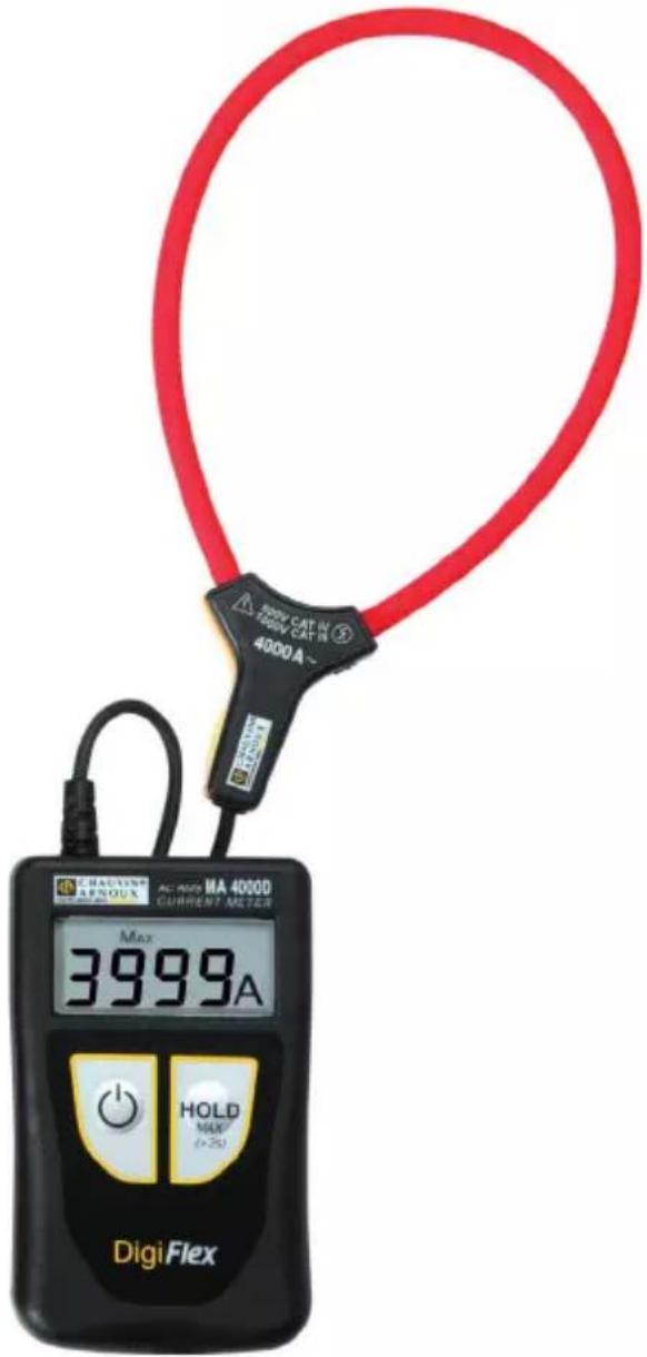
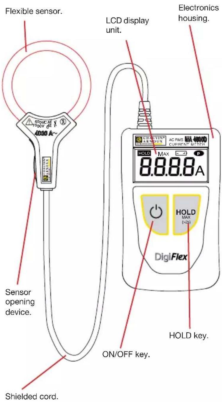
The DigiFLEX is used for RMS measurements of current, from 200 mA to 4000 A.
The sensor takes the form of a flexible coil 35 cm long, connected by a shielded cord to a small housing containing the signal processing electronics, supplied by a battery.
The flexibility of the sensors makes it easier to wrap them round the conductor to be measured, whatever its type (cable, bar, strand, etc.) and its accessibility. The design of the snap-action coil opening and closing device allows it to be handled while wearing protective gloves.
text_image
Flexible sensor. 500VCA AT 1000V CT 4000 A~ Sensor opening device. Shielded cord. LCD display unit. Electronics housing. DigiFlex AC RMS MAX 4000D CURRENT METER HOLD MAX 8.8.8.8A HOLD MAX (>2s) ON/OFF key. HOLD key.On the back of the electronics housing is a notch for the attachment of a belt clip (optional).
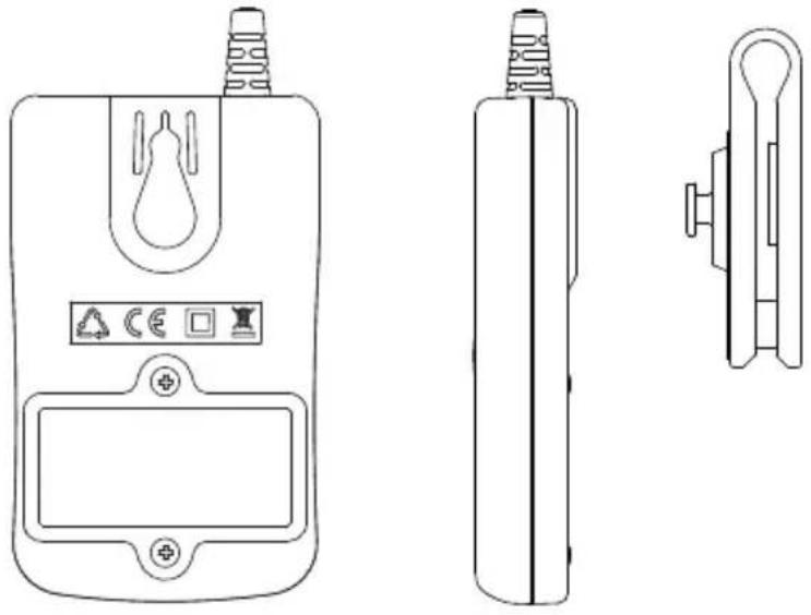
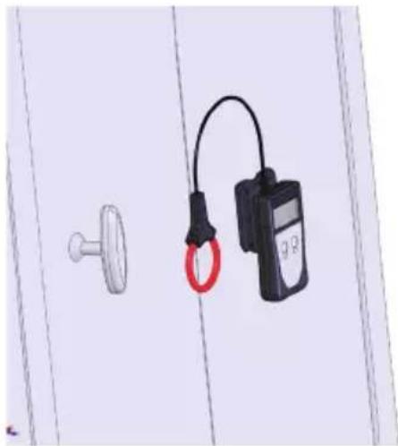
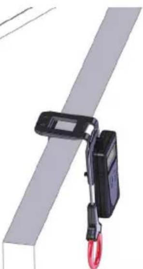
The multi-function belt clip can be used:
■ to carry the electronic housing on your belt,
natural_image
Illustration of a wall-mounted device connected to a circular component and a ring, with no visible text or symbols.■ to attach it to a metal surface using the built-in magnet,
■ to hook it to a door or the edge of a table.
natural_image
Mechanical device with red ring attached to a gray beam, no visible text or symbols2. CURRENT MEASUREMENT
2.1. MEASUREMENT PRINCIPLE
The flexible sensor is based on the Rogowski coil.
It combines:
■ very good linearity with no saturation effect (and so no heating);
■ light weight (no magnetic circuit).
2.2. USE
2.2.1. CONNECTION
First of all, use the appropriate means of protection.
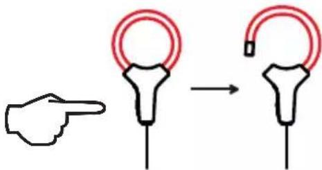
■ Press the yellow opening device to open the flexible coil.
text_image
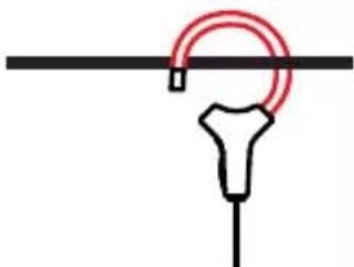
Diagram illustrating a hand pointing to a medical or surgical device with a red ring and arrow indicating transformation.■ Open it, then place it round the conductor through which the current to be measured flows (only one conductor in the sensor).
■ Close the coil.
natural_image
Simple line drawing of a bone joint with a curved ring and connecting rod (no text or symbols)In order to optimize measurement quality, it is best to centre the conductor in the coil and to make the shape of the coil as nearly circular as possible.
■ Press the key to switch the device on. The display unit lights.
2.2.2. MEASUREMENT
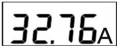
Read the measurement on the display unit. The current is given in ARMS.
text_image
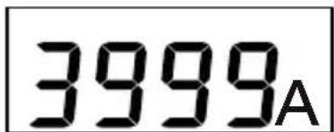
32.76AIf the measurement exceeds the display capacity (4000 A), the device displays 3999, blinking.
text_image
3999AIf the measurement is too low (see § 3.2), the device displays dashes.
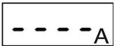
text_image
- - - - - AIf the edges of the signal are too steep or its peak factor is too large, the device displays OL.
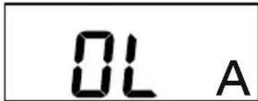
text_image
OL A2.2.3. FREEZING THE MEASUREMENT
If you want to freeze the display of a measurement, press the HOLD key.
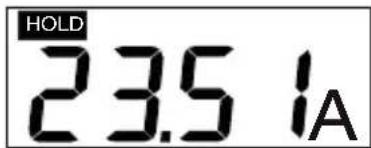
text_image
HOLD 23.5 I_AThe HOLD symbol is displayed.
The device continues to make measurements, but the display is frozen. To release it, press the HOLD key again.
2.2.4. SEARCH FOR MAXIMUM
To search for a maximum, for example a spike lasting at least 100 ms, press the HOLD (MAx > 2s) key for more than two seconds.
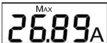
text_image
MAX 26.89AThe MAX symbol is then displayed; the device starts making measurements a few seconds later.
The device compares each new measurement to the one displayed. If the new measurement is greater than the old, it replaces it in the display.
To return to the real-time display mode, press the HOLD (MAx > 2s) key again.
2.2.5. DE-ACTIVATION OF AUTOMATIC SWITCHING OFF
In order to save the batteries, the device switches itself off automatically at the end of 10 minutes if the user has not pressed a key (unless the MAX function is active).
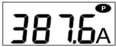
It is possible to deactivate automatic switching off. To do this, when you switch the device on, press the ⏻ and HOLD keys simultaneously. The P symbol (lit steadily) is then displayed.
text_image
38.76ATo reactivate automatic switching off, switch the device off, then back on.
2.2.6. BATTERIES LOW
When the battery voltage drops and the remaining battery life of the device is only about one hour, the - + symbol blinks on the display unit.
When the battery voltage is too low to guarantee the accuracy of the measurements, the - + symbol lights steadily. The batteries must then be replaced (see § 4.2).
2.2.7. DISCONNECTING
■ Switch the device off by pressing the key.
■ Press the yellow opening device to open the flexible core.
■ Remove the flexible core from the conductor.
3. CHARACTERISTICS
3.1. REFERENCE CONDITIONS
| quantity of influence Reference values | |
| Temperature 23 ± 3^ | |
| Relative humidity 45 to 75% RH | |
| Frequency of the signal measured 40 to 65 Hz | |
| Peak factor of the signal measured | 2 |
| Conductor diameter ≤ 5 mm | |
| Battery voltage 2.8 - 3.2 V | |
| External electric field none | |
| External DC magnetic field (earth field) | <40 A/m |
| External AC magnetic field none | |
| Position of the conductor | centred in the measurement coil |
| Shape of the measurement coil nearly circular | |
3.2. ELECTRICAL CHARACTERISTICS
| Display range (A) 40 | 400 4000 | ||
| Specified measurement range (A) | 0.20 - 39.99 | 40.0 - 399.9 | 400 - 3999 |
| Resolution 10 mA 100 | mA 1 A | ||
| Intrinsic uncertainty | ±(2% + 10 ct) | ±(1.5% + 2 ct) | ±(1.5% + 2 ct) |
In MAX mode:
| Display range (A) 40 | 400 4000 | ||
| Specified measurement range (A) | 1.00 - 39.99 | 40.0 - 399.9 | 400 - 3999 |
| Resolution 10 mA 100 | mA 1 A | ||
| Typical error | ±(2% + 10 ct) | ±(1.5% + 2 ct) | ±(1.5% + 2 ct) |
3.3. VARIATIONS IN RANGE OF USE
| Quantity of influence Range of influence | |
| Battery voltage 1.8 to 2 V | |
| Temperature | 0 °C to 50 °C |
| Relative humidity 10 to 90% | RH |
| Frequency response | 10 to 20 Hz20 Hz to 30 Hz30 Hz to 400 Hz400 to 1000 Hz1000 to 3000 Hz |
| Position of the conductor in the sensor (f<400 Hz) | Any position on the interior perimeter of the sensor |
| Adjacent conductor carrying alternating current | Conductor touching the exterior perimeter of the sensor |
| Peak factor | 1.4 to 3.5 limited to 6000 Apeak |
| Serial mode rejection ratio in AC | 0 to 400 ADC |
| Common mode rejection, 50/60 Hz | 0 to 600 VRMS |
| Influence of a 50/60 Hz external magnetic field | 0 to 400 A/m |
3.4. TYPICAL FREQUENCY RESPONSE CURVES
at 39 AAC
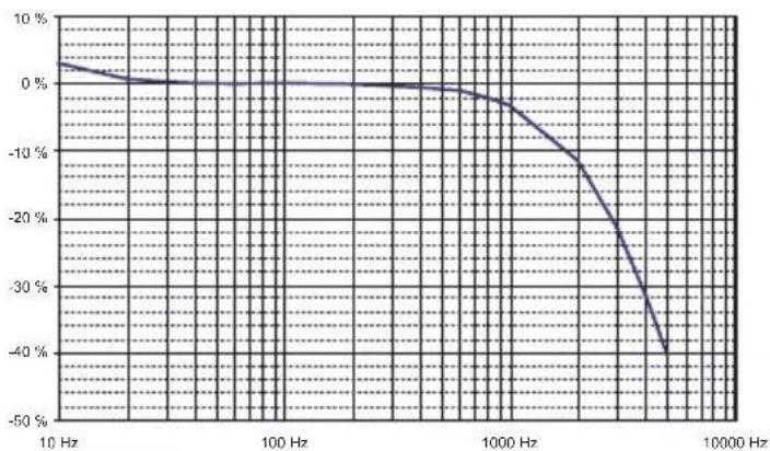
line
| Frequency | Value | | --------- | ------ | | 10 Hz | 0% | | 100 Hz | 0% | | 1000 Hz | -10% | | 10000 Hz | -40% || Error on the measurement | |
| Typical Maximum | |
| < 1 ct ±(2% + 1 ct) | |
| See § 3.4 | ± (5 % + 1 ct)± (1 % + 1 ct)± (0.5 % + 1 ct)± (6 % + 1 ct)- 3 dB typical |
| ± 0.5 % ± (1.5 % ± 1 ct) | |
| Away from opening: 55 dBAt opening: 55 dB | Away from opening: ≥ 45 dBAt opening: ≥ 45 dB |
| at 16.66 Hz : ± (2 % + 1 ct)at 50 Hz : ± (0.5 % + 1 ct)at 440 Hz : ± (30 % + 1 ct) | ± (6 % + 1 ct)± (3 % + 1 ct)- |
| Housing: 43 dBSensor: 50 dB | Housing: ≥ 30 dBSensor: ≥ 40 dB |
3.5. POWER SUPPLY
The device can be powered:
■ either by two 1.5 V R03 (AAA) alkaline batteries,
■ or by two NiMH storage batteries of the same size.
The nominal operating voltage is between 1.8 and 3.2 V.
The battery life in continuous operation is:
■ 70 hours with super-alkaline batteries,
■ 50 hours with NiMH storage batteries having a capacity of 1200 mAh.
The low battery condition is reported by the blinking symbol on the display unit. When it is lit steadily, the batteries must be replaced (see § 4.2).
3.8. ENVIRONMENTAL CONDITIONS
The instrument must be used in the following conditions:
■ Temperature in use: 0°C to +50°C
■ Storage temperature: -20^ to +70^
(without batteries)
■ Relative humidity in use: 80% RH to 50°C
■ Relative humidity in storage: 90% RH (up to 45°C)
The sensor can withstand a temperature of 90^ C.
For indoor use.
Level of pollution: 2.
Altitude: <2000 m.
3.7. CHARACTERISTICS OF CONSTRUCTION
Overall dimensions
■ Housing: 100 x 60 x 20 mm
■ Connecting cable: 0.70 m
■ Sensor
■ Length (mm) 350 mm
■ Clamping diameter 100 mm
Mass of the device: approximately 130 g.
Index of protection: IP 40 per IEC 60529
IK 04 per IEC 50102
Afterflame time: V0 (per UL 94)
The flexible coil is resistant to oils and aliphatic hydrocarbons.
3.8. COMPLIANCE WITH INTERNATIONAL STANDARDS
Electrical safety per IEC 61010-2-032 for type B sensors.
Rated voltage 600 V with respect to earth in category IV.
Double insulation:

3.9. ELECTROMAGNETIC COMPATIBILITY
Emissions and immunity in an industrial setting compliant with IEC 61326-1 for portable devices.
4. MAINTENANCE

Any unauthorized repair or replacement of a part "equivalent" may gravely impair safety.
4.1. CLEANING
Disconnect everything connected to the instrument and switch it off.
Use a soft cloth, dampened with soapy water. Rinse with a damp cloth and dry rapidly with a dry cloth or forced air. Do not use alcohol, solvents, or hydrocarbons.
Make sure that no foreign body interferes with the operation of the snap device of the sensor.
4.2. REPLACEMENT OF THE BATTERIES
The battery must be replaced when the green indicator flashes or remains off when the instrument is switched on.
■ Disconnect everything connected to the instrument and and switch it off.
■ Use a screwdriver to unscrew the two closing screws of the housing.
■ Replace the old battery with a new battery (1.5 V R03 or AAA super-alkaline batteries).
■ Close the housing; make sure that it is completely and correctly closed.
■ Screw both screws back in.
Spent batteries must not be treated as ordinary household waste. Take them to the appropriate recycling collection point.
4.3. METROLOGICAL CHECK

Like all measuring or testing devices, regular instru-t verification is necessary.
This instrument should be checked at least once a year. For checks and calibrations, contact one of our accredited metrology laboratories (information and contact details available on request), at our Chauvin Arnoux subsidiary or the branch in your country.
4.4. REPAIR
For all repairs before or after expiry of warranty, please return the device to your distributor.
5. WARRANTY
Except as otherwise stated, our warranty is valid for twelve months starting from the date on which the equipment was sold. Extract from our General Conditions of Sale, provided on request.
The warranty does not apply in the following cases:
■ inappropriate use of the equipment or use with incompatible equipment;
■ modifications made to the equipment without the explicit permission of the manufacturer's technical staff;
■ work done on the device by a person not approved by the manufacturer;
■ adaptation to a particular application not anticipated in the definition of the equipment or not indicated in the user's manual;
■ damage caused by shocks, falls, or floods.
6. TO ORDER
DigiFLEX MA4000D-350 P01120577Z
Delivered in a blister pack with:
■ two 1,5 V piles alkaline battery (AAA),
■ one Velcro fastener
■ one user's manual in 5 languages,
■ one certificate of verification.
6.1. ACCESSORIES
Carrying bag 120x200x60 P01298074
Multi-function belt clip P01102100Z
6.2. REPLACEMENT PARTS
Set of 5 Velcro fasteners P01102113
natural_image
Illustration of a wall-mounted device connected to a circular component and a ring, with no visible text or symbols.natural_image
Mechanical device with red ring attached to a gray beam, no visible text or symbols2. STROMMESSUNGEN
2.1. MESSGRUNDLAGE
text_image
Diagram illustrating a hand pointing to a medical device with a red circular component, followed by a transformation arrow.natural_image
Simple line drawing of a bone joint with a curved ring and connecting rod (no text or symbols)text_image
HOLD 23.5 1Atext_image
MAX 26.89Anatural_image
Illustration of a wall-mounted device connected to a circular component and a ring, with no visible text or symbols.natural_image
Mechanical device with red ring attached to a gray beam, no visible text or symbols2. MISURA DELLA CORRENTE
text_image
Diagram illustrating a hand pointing to a circular connector with a red ring, followed by a curved connector with a plug.natural_image
Simple line drawing of a bone joint with a curved ring and connecting rod (no text or symbols)text_image
HOLD 23.5 I_Atext_image
MAX 26.89Anatural_image
Illustration of a wall-mounted device connected to a circular component and a ring, with no visible text or symbols.natural_image
Mechanical device with red ring attached to a gray beam, labeled 'a' (no text or symbols on the device itself)text_image
Diagram illustrating a hand pointing to a medical device with a red circular component, followed by a transformation arrow.natural_image
Simple line drawing of a bone joint with a red circular ring and connecting rod (no text or symbols)text_image
HOLD 23.5 1Atext_image
MAX 26.89AUnit 1 Nelson Ct - Flagship Sq - Shaw Cross Business Pk
Dewsbury, West Yorkshire - WF12 7TH
Tel: 01924 460 494 - Fax: 01924 455 328
MIDDLE EAST - Chauvin Arnoux Middle East
P.O. BOX 60-154 - 1241 2020 JAL EL DIB (Beirut) - LEBANON
Tel: (01) 890 425 - Fax: (01) 890 424
CHINA - Shanghai Pu-Jiang - Enerdis Instruments Co. Ltd
3 F, 3 rd Building - N° 381 Xiang De Road - 200081 SHANGHAI
Tel: +86 21 65 21 51 96 - Fax: +86 21 65 21 61 07
USA - Chauvin Arnoux Inc - d.b.a AEMC Instruments
200 Foxborough Blvd. - Foxborough - MA 02035
Tel: (508) 698-2115 - Fax: (508) 698-2118
http://www.chauvin-arnoux.com