C.A 5233 - Multimeter CHAUVIN ARNOUX - Free user manual and instructions
Find the device manual for free C.A 5233 CHAUVIN ARNOUX in PDF.


User questions about C.A 5233 CHAUVIN ARNOUX
0 question about this device. Answer the ones you know or ask your own.
Ask a new question about this device
Download the instructions for your Multimeter in PDF format for free! Find your manual C.A 5233 - CHAUVIN ARNOUX and take your electronic device back in hand. On this page are published all the documents necessary for the use of your device. C.A 5233 by CHAUVIN ARNOUX.
USER MANUAL C.A 5233 CHAUVIN ARNOUX
text_image
100T ENGLISH PLA2003. FONCTIONS
3.1 FONCTIONS DU COMMUTATEUR
4.2.1 Tensions continues
This device complies with safety standard IEC-61010-1 for voltages up to 600V in category IV, at an altitude below 2000m, indoors, with a pollution level of not more than 2.
Failure to observe the safety instructions may cause an electric shock, fire, explosion, or destruction of the instrument and of the installations.
- Do not use the instrument in an explosive atmosphere or in the presence of flammable gases or fumes.
- Do not use the instrument on networks of which the voltage or category exceeds those mentioned.
- Do not exceed the rated maximum voltages and currents between terminals or with respect to earth.
- Do not use the instrument if it appears to be damaged, incomplete, or not properly closed.
■ Before each use, check the condition of the insulation on the leads, housing, and accessories. Any element of which the insulation is deteriorated (even partially) must be set aside for repair or scrapped.
■ Use leads and accessories rated for voltages and categories at least equal to those of the instrument. - Observe the environmental conditions of use.
- Do not modify the instrument and do not replace components with "equivalents". Repairs and adjustments must be done by approved qualified personnel.
- Replace the battery as soon as the □ symbol appears on the display unit. Disconnect all leads before opening the battery compartment cover.
■ Use personal protective equipment when conditions require. - Keep your hands away from the unused terminals of the instrument.
- When handling probes or contact tips, keep your fingers behind the guards.
MEASUREMENT CATEGORIES
Definitions of the measurement categories according to standard IEC 61010-1:
CAT I: Circuits not directly connected to the network and specially protected.
Example: protected electronic circuits.
CAT II: Circuits directly connected to the low-voltage installation.
Example: power supply to household electrical appliances and portable tools.
CAT III: Power supply circuits in the installation of the building.
Example: distribution panel, circuit-breakers, fixed industrial machines or devices.
CAT IV: Circuits supplying the low-voltage installation of the building.
Example: power lines, meters, and protection devices.
Français 2
Deutsch 57
Italiano....84
Español 111
Thank you for purchasing a C.A. 5233 multimeter.
For best results from your device:
- Read this user manual attentively;
- Observe the precautions for its use.
Meaning of the symbols used on the instrument:

Risk of danger. The operator agrees to refer to these instructions whenever this danger symbol appears.
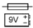
Fuse.
9V battery.

The CE marking indicates compliance with European directives.

Double or reinforced insulation.
Selective sorting of wastes for the recycling of electrical and electronic equipment within the European Union. In conformity with directive DEEE 2002/96/EC: this equipment must not be treated as household waste.
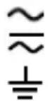
AC – Alternating current.
AC or DC – Alternating or direct current.
Earth.
CONTENTS
1. PRESENTATION ...... 34
1.1 THE DISPLAY UNIT 35
1.2 THE KEYS....37
1.3 THE SWITCH....38
1.4 THE TERMINALS 39
2. USE 40
2.1 FIRST USE....40
2.2 POWERING UP THE MULTIMETER....40
2.3 POWERING DOWN THE MULTIMETER 40
2.4 THE PROP 41
3. FUNCTIONS....42
3.1 FUNCTIONS OF THE SWITCH 42
3.2 FUNCTIONS OF THE KEYS 46
4. CHARACTERISTICS ....50
4.1 REFERENCE CONDITIONS .... 50
4.2 CHARACTERISTICS AT THE REFERENCE CONDITIONS ... 50
4.3 ENVIRONMENTAL CONDITIONS....54
4.4 CHARACTERISTICS OF CONSTRUCTION....54
4.5 POWER SUPPLY 54
4.6 compliance with international standards....55
4.7 VARIATIONS IN DOMAIN OF USE ....55
5. MAINTENANCE .... 56
5.1 CLEANING....56
5.2 REPLACING THE BATTERY 56
5.3 REPLACING THE FUSE....56
5.4 METROLOGICAL CHECK....56
5.5 REPAIR 57
6. WARRANTY....57
7. TO ORDER....57
1. PRESENTATION
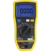
The C.A 5233 is a TRMS digital multimeter, specially designed to combine in a single instrument the various functions and measurements of the following electrical quantities:
■ AC voltmeter with low input impedance (voltage measurements in the fields of electricity and electrical engineering);
■ AC or DC voltmeter with high input impedance (voltage measurements in the field of electronics);
■ Measurement of frequency and duty cycle;
■ Ohmmeter:
■ Continuity test with buzzer;
Diode test:
■ Ammeter:
■ Capacitance meter;
■ Thermometer in °C or °F by measurement and linearization of the voltage across the terminals of a type K thermocouple;
■ Contact-free detection of presence of network voltage (NCV function, presence of phase).
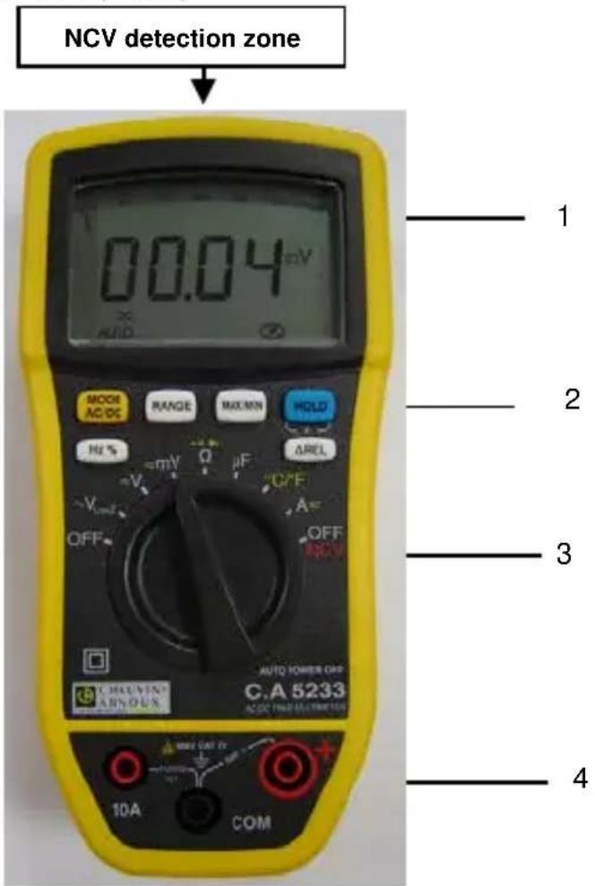
text_image
NCV detection zone 00.04 mV MODE AC/DC RANGE MAX/EN HOLD Hz % -V Ω pF AREL VOUT OFF OFF 10A COM AUTO POWER ORP C.A 5233 AC/CC FINE ELECTRONICS 1 2 3 4Figure 1 : the C.A 5233 multimeter
English
| Item | Designation | See § |
| 1 | Display unit | 1.1 |
| 2 | Function keys | 1.2 |
| 3 Switch 1.3 | — | |
| 4 Terminals 1.4 | — | |
1.1 THE DISPLAY UNIT
The display unit allows :
■ An analog display of the parameter measured, in the form of a bargraph, associated with a 6,000-point digital display.
■ Comfortable reading of the information thanks to the backlighting of the screen.
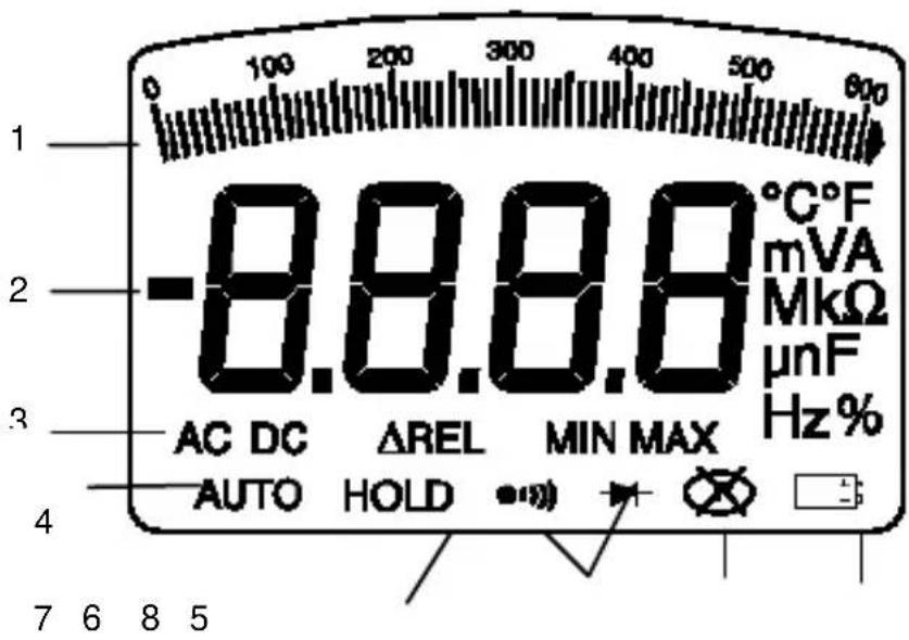
text_image
1 0 100 200 300 400 500 600 -8.8.8.8 °C°F mVA MkΩ μnF Hz % AC DC ΔREL MIN MAX AUTO HOLDFigure 2 : the display
English
| Item | Function | See § |
| 1 Bargraph | ||
| 2 | Display (values and units of measurement) | 3.1 |
| 3 Nature of the measurement (AC or DC) 3.2.1 | — | |
| 4 Automatic measurement range selection mode 3.2.2 | — | |
| 5 Low battery indicator 5.2 | — | |
| 6 Audible continuity testDiode test | 3.1.33.1.4 | |
| 7 Display of the modes selected 1.2 | — | |
| 8 Non-Permanent Mode : automatic switching off of the device activated | 3.2.1 | |
1.1.1 The symbols on the display unit
The display unit uses the following symbols:
| Symbol | Designation |
| AC | Alternating current |
| DC | Direct current |
| AUTO | Automatic change of range (see § 1.1.3) |
| HOLD | Storage and display of stored values |
| MAX | Maximum RMS value |
| MIN | Minimum RMS value |
| REL | Relative value |
| O.L | Overshoot of measurement capabilities (see §1.1.2) |
| V | Volt |
| Hz | Hertz |
| % | Duty Cycle |
| F | Farad |
| °C | Degrees Celsius |
| °F | Degrees Fahrenheit |
| A | Ampere |
English
| Ω | Ohm |
| n | Prefix, nano- |
| μ | Prefix, micro- |
| m | Prefix, milli- |
| k | Prefix, kilo- |
| M | Prefix, Mega- |
| ●)) | Audible continuity test |
| → | Diode test |
 | Non-Permanent Mode (automatic switching off activated) |
| Low battery indicator |
1.1.2 Overshoot of measurement capabilities (O.L.)
The O.L. (Over Load) symbol is displayed when the signal measured exceeds the range of the device.
1.1.3 Automatic change of measurement range (Auto-Range)
The AUTO symbol on the display unit indicates that the instrument automatically changes the measurement range to make the measurement. You can change the range manually by pressing RANGE (see § 3.2.2).
1.2 THE KEYS
The keypad has six keys: MODE ACDC, RANGE MAXIM, HOLD Hz % et ΔREL. Here are the keys of the keypad.
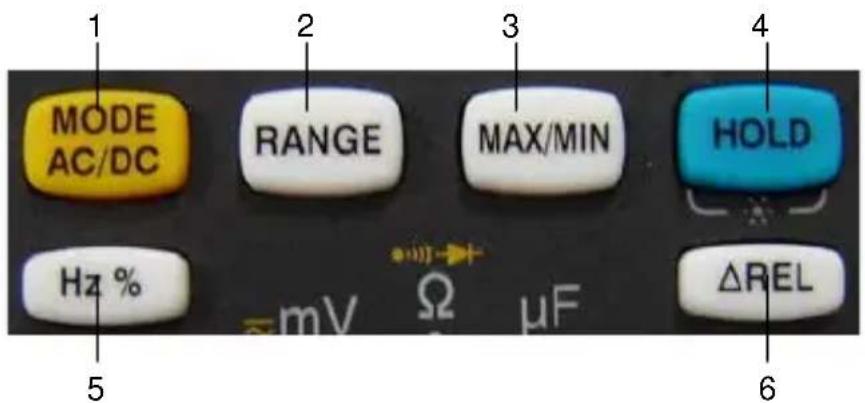
text_image
MODE AC/DC RANGE MAX/MIN HOLD Hz % mV Ω μF ΔREL 5 6Figure 3 : the keys on the keypad
| Item | Function See § | |
| 1 | Selection of the type of measurement (AC or DC), ●, °C, °F or ➤. Activation or de-activation of the automatic switching off of the device at start-up. | 3.2.1 |
| 2 | Manual selection of the measurement range. 3.2.2 | — |
| 3 | Activation or de-activation of the MAX/MIN mode. | 0 |
| 4 | Hold of display of the measured value.Activation or de-activation of the blue back-lighting of the screen (☒) (press >2s). | 0 |
| 5 | Frequency and duty cycle measurement in V AC and A AC | 3.2.5 |
| 6 | Measurement of the relative value | 3.2.6 |
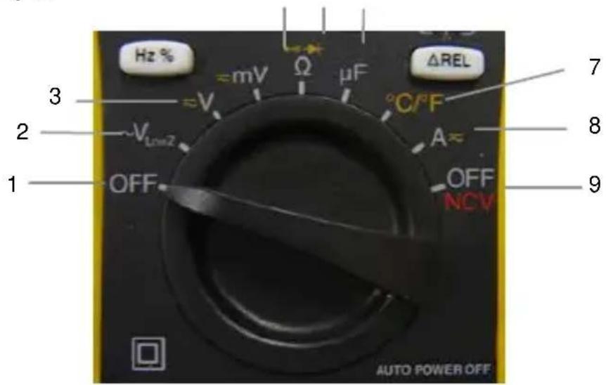
1.3 THE SWITCH
The switch has seven positions. The functions are described in the table below :
4 5 6
text_image
Hz % ≈mV Ω μF ΔREL 3 ~V °C/°F 2 ~V_L=2 A~ 1 OFF OFF NCV AUTO POWER OFFFigure 4 : the switch
English
| Item | Function See § | |
| 1 | OFF mode – Powers down the multimeter | 2.3 |
| 2 | AC voltage measurement at low input impedance ( V_LowZ ) | 3.1.1 |
| 3 AC | or DC voltage measurement (V) 3.1.1 | — |
| 4 | AC or DC voltage measurement (mV) | 3.1.1 |
| 5 Resistance measurement | 3.1.2 | |
| 3.1.3 | ||
| 3.1.4 | ||
| 6 | Capacitance measurement | 3.1.5 |
| 7 Temperature measurement in °C or °F 3.1.6 | — | |
| 8 AC | or DC current measurement 3.1.7 | |
| 9 NVC (Non-Contact Voltage) + Partial OFF mode of the multimeter (NCV function active) | 3.1.8 | |
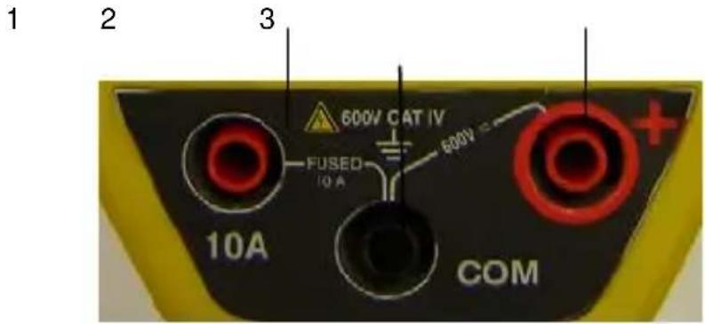
1.4 THE TERMINALS
The terminals are used as follows:
text_image
1 2 3 600V CAT IV FUSED 10 A 600V + 10A COMFigure 5 : the terminals
| Item Function | |
| 1 | Current measurement terminal (10 A) |
| 2 | Cold point terminal (COM) |
| 3 | Hot point terminal (+) |
2. USE
2.1 FIRST USE
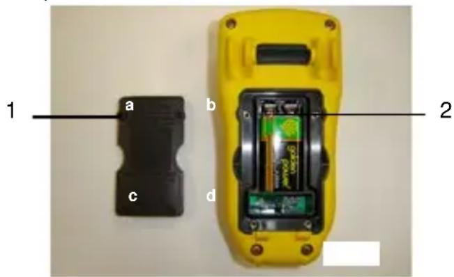
Insert the battery provided with the instrument as follows:
- Using a screwdriver, unscrew the four screws (a, b, c, and d) holding the cover (item 1) on the back of the housing;
- Place the battery in its compartment (item 2); watch out for the polarity;
- Screw the cover back onto the housing. Put the stand back in place.
text_image
1 a b c d 2Figure 6 : access to the battery
2.2 POWERING UP THE MULTIMETER
The switch is set to OFF. Turn the switch to the function of your choice. All segments of the display unit light for a few seconds (see figure 2, § 1.1) the screen corresponding to the chosen function then appears. The multimeter is now ready for measurements.
2.3 POWERING DOWN THE MULTIMETER
The multimeter can be switched off manually, by setting the switch to OFF, it will also switch itself off automatically if left unused for 15 minutes. At the 14th minute, 5 beeps warn that the multimeter is about to be switched off. To reactivate the instrument, press any key on the keypad.
Note: the OFF position does not completely switch off the multimeter; it remains active for contact-free detection of the presence of the network voltage (NCV).
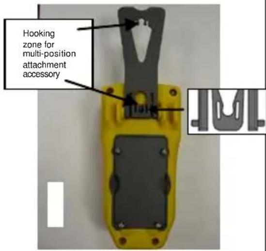
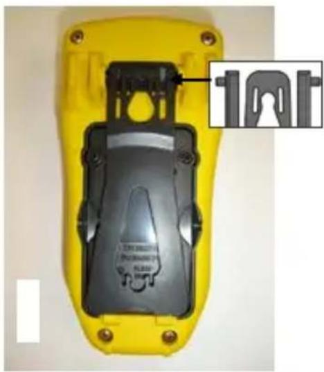
2.4 THE PROP
The prop can be placed in either of two positions according to how it is to be used: to suspend the multimeter from a hook (position 1) or to stand it in an inclined position on a support (position 2). To change the position of the prop, proceed as follows:
Position 1 : raise the stand
text_image
Hooking zone for multi-position attachment accessoryPosition 2 : lower the stand
text_image
100T3. FUNCTIONS
3.1 FUNCTIONS OF THE SWITCH
To access to the functions of the switch, set the switch to


3.1.1 Voltage measurement
The instrument measures:
■ the AC voltage at low input impedance (VLowZ);
■ direct voltages (DC);
■ alternating voltages (AC).
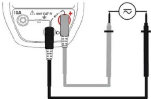
To measure a voltage, proceed as follows:
- Set the switch to V_lowZ , V ; w on set to

the device is in AC mode only ;
-
For ≈ V or ≈ mV , select AC or DC by pressing MODE AC/DC. As default, the device is in DC mode. Depending on your selection, the screen displays AC or DC.
-
Connect the black lead to the COM terminal and the red lead to “+”;
-
Place the contact tips on the terminals of the circuit to be measured;
text_image
10A 600% CAT IV CThe measured voltage is displayed on screen.
3.1.2 Resistance measurement
Attention: all resistance measurements must be made in the absence of any voltage.
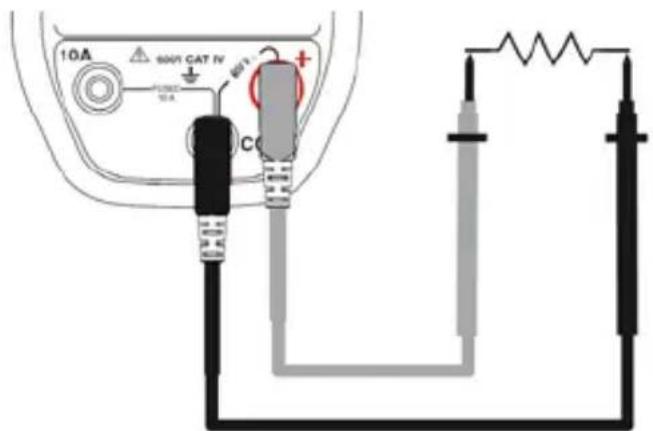
To measure a resistance, proceed as follows:
- Set the switch to
- Connect the black lead to the COM terminal and the red lead to “+”;
- Place the contact tips on the terminals of the component or circuit to be measured;

English
text_image
10A 600V CAT IV C +The measured resistance is displayed on screen.
3.1.3 Continuity test with buzzer
Attention: all continuity measurements must be made in the absence of any voltage.
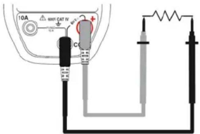
To test electrical continuity, proceed as follows:
- Set the switch to

-
Press MODE AC/DC. The symbol is displayed;
-
Connect the black lead to the COM terminal and the red lead to “+”;
-
Place the contact tips on the terminals of the component or circuit to be tested;
text_image
10A 600V CAT IV C +The buzzer indicates continuity; the measured resistance is displayed on screen.
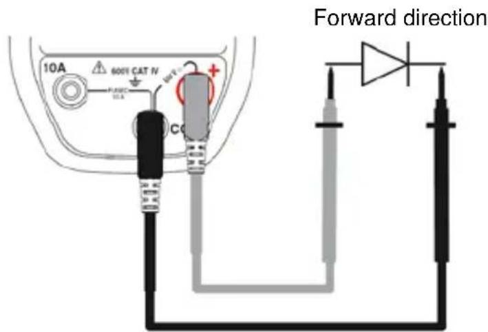
3.1.4 Diode test
Attention: all diode test measurements must be made in a power-off condition.
To test a diode, proceed as follows:
- Set the switch to

- Press MODE twice. The ➕ symbol is displayed;
- Connect the black lead to the COM terminal and the red lead to “+”;
- Place the contact tips on the terminals of the component;
text_image
Forward direction 10A 600% CAT N PANC PLA CO +The voltage across the terminals of the component is displayed on screen.
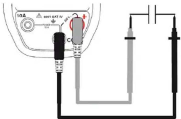
3.1.5 Capacitance measurement
Attention: all capacitance measurements must be made in a power-off condition. Observe the connection polarity (+ to the red terminal, - to the black terminal)
To measure the capacitance, proceed as follows:
- Make sure that the capacitor to be measured is discharged;
- Set the switch to F ;
- Connect the black lead to the COM terminal and the red lead to “+”;
- Place the contact tips on the terminals of the component;
text_image
10A 600% CAT IV 50kV + - Power 10A CThe measured capacitance is displayed on screen.
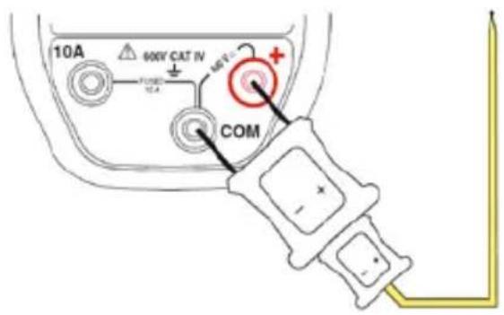
3.1.6 Temperature measurement
To measure the temperature, proceed as follows:
- Set the switch to

- Press MODE AC/DC to select the temperature unit and scale (°C or °F);
Remark: the default is °C.
-
Connect the temperature probe adapter (item 1) to the COM and “+” terminals, observing the polarity;
-
Connect the temperature probe (item 2) to the adapter, observing the polarity;
Note: if the probe is disconnected or open-circuit, the display unit indicates OL.
text_image
10A 60KV CAT IN FUSED 10A COM 60kV CAT IN +The thermocouple temperature indication is displayed on screen.
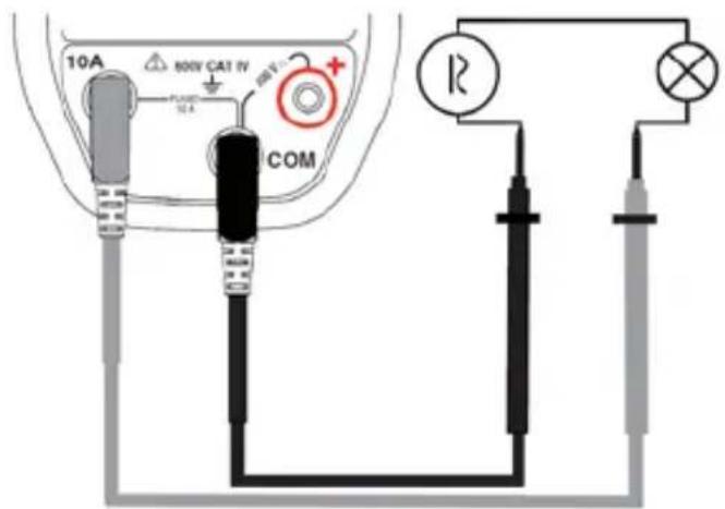
3.1.7 Current measurement

- Set the switch to
- Select AC or DC by pressing MODE AC/DC. As default, the device is in DC mode. According to your selection, the screen displays DC or AC;
- Connect the black lead to the COM terminal and the red lead to "10A";
- Connect the multimeter in series in the circuit.
text_image
10A 800V CAT IV PLUMB 10A COM RThe measured current is displayed on screen.
3.1.8 Non-Contact Voltage NCV
- Set the switch to

- Move the C.A 5231 (NCV detection zone) close to the potentially live conductor(s) (presence of phase);
- If a network voltage of 230V is present (Europe model), the back-lighting lights red; otherwise, it remains off.
3.2 FUNCTIONS OF THE KEYS
The functions of the MODE AC/DC, RANGE, MAXRES, HOLD, Hz % and REL keys can be accessed by successive short or long presses. Each press is confirmed by an audible signal.
3.2.1 The key MODE AC/DC
This key is used to select the type of measurement and the display mode to deactivate the automatic switching off of the device, at start-up, in combination with the switch. A long press during start-up, while turning the OFF switch to any position, deactivates automatic switching off. The symbol is not displayed. As default, automatic switching off is activated and the symbol is displayed.
Remark : the Dc mode is activated as default.
English
| Each pres of this length... |  | ...serves to |
| short | [W32K]  | Change the nature of the measurement AC or DC. |
 | Select the continuity test 🎨 or diode test mode. | |
 | To display the temperature in degrees Celsius (°C) or in degrees Fahrenheit (°F). |
3.2.2 The key RANGE
This key is used to choose a measurement range manually. The range defines the maximum measurement span of which the device is capable.
Remark: the Auto-range mode is activated as default.
| Each press of this length... |  | ...serves to |
| short |   | To change the measurement range manually (span and resolution). |
| Long (> 2 sec) |     | To return to Auto-range mode. |
Remark 1: the continuity test and diode test -odes are not Auto-range.
Remark 2: the Capacitance Measurement mode μF is Auto-range only.
3.2.3 The key
This key is used to store and display, successively, the current, maximum, and minimum TRMS values.
The MODE AC/DC, RANGE, HOLD, Hz % and ΔREL, keys are inactive in the MAX/MIN mode. The AUTO mode is deactivated.
| Each press of this length... |  | ...serves to |
| 1^st short Activate MAX/MIN storage. | ||
| short | At each press, to view in turn the MAX, MIN, and current value.Remark:the MAX value is displayed as default. | |
| Long (>2 sec) | Exit from themode. | |
3.2.4 The key
This key is used to hold the display of the measured value, and to activate/deactivate the backlighting of the screen.
| Each press of this length... |  | ...serves to |
 | ||
| court |  | To hold the display of the measured value;To exit from the mode. |
 | ||
 | ||
| long (>2 sec) |  | to activate/deactivate the backlighting of the screen. |
 | Note: the backlighting is switched off at the end of 10 seconds. | |
 |
3.2.5 The key
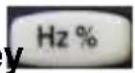
This key is used to display the frequency of the AC signal measured, along with the duty cycle.
It is inactive in DC mode.
| Each press of this length... |  | ...serves to |
 | ||
| short |  | to display the frequency,to display the duty cycle,to exit from theHz %mode |
 | ||
 |
3.2.6
The
key
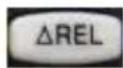
This key is used to display the value relative to a reference stored when the key was pressed.
For example, if the value stored when the key was pressed = 10V and the current value is 11.5V, the display in relative mode will be 11.5 - 10 = 1.5V.
Note: the Auto-Range mode is deactivated.
| Each press of this length... |  | ...serves to |
 | ||
| short |  | to display the relative value;to exit from themode. |
 | ||
| long (>2 sec) |  | To deactivate automatic switching off. |
 | ||
 | ||
 |
4. CHARACTERISTICS
4.1 REFERENCE CONDITIONS
| Quantities of influence | Reference conditions |
| Temperature : | 23 °C ± 2 °C |
| Relative humidity : | 45 % to 75 % |
| Supply voltage : 8.5 V ± 0.5 V |
4.2 CHARACTERISTICS AT THE REFERENCE CONDITIONS
The uncertainty is expressed in the form x% of the reading + y counts, from 10% to 100% of each measurement range.
4.2.1 Direct voltages
The input impedance is 10MΩ.
■ mV DC
| Range Resolution | Uncertainty (±) | |
| 60 mV | 0.01 mV | 1 % + 12 cts |
| 600 mV | 0.1 mV | 0.6 % + 2 cts |
■ V DC
| Range Resolution | Uncertainty (±) | |
| 600 mV | 0.1 mV | 0.6 % + 2 cts |
| 6 V 0.001 V | 0.2 % + 2 cts | |
| 60 V 0.01 V | ||
| 600 V 0.1 V | ||
| 1000 V * | 1 V | |
* According to safety rules, 1000V range is limited to 600V.
4.2.2 Alternating voltages
The input impedance is 10 MΩ.
■ mV AC True RMS
| Range Resolution | Uncertainty (±)45 Hz to 60 Hz | Uncertainty (±)60 Hz to 1 kHz | |
| 60 mV | 0.01 mV | 2 % + 12 cts | 2.5 % + 12 cts |
| 600 mV | 0.1 mV | 2 % + 3 cts | 2.5 % + 3 cts |
■ V AC True RMS
| Range Resolution | Uncertainty (±)45 Hz to 60 Hz | Uncertainty (±)60 Hz to 1 kHz | |
| 6 V 0.001 V | 2 % + 3 cts 2.5 | % + 3 cts | |
| 60 V 0.01 V | |||
| 600 V 0.1 V | |||
| 1000 V * 1 V | |||
* According to safety rules, 1000V range is limited to 600V.
4.2.3 Alternating voltages at low impedance (V AC LowZ True RMS)
The input impedance is 270kΩ.
A low input impedance serves to eliminate the effects of interference voltages due to the supply network, and makes it possible to measure an AC voltage with a minimum of error.
| Range Resolution | Uncertainty (±) |
| 6 V 0.001 V | 45 Hz à 60 Hz2 % + 10 cts |
| 60 V 0.01 V | |
| 600 V 0.1 V | |
| 1000 V 1 V |
* According to safety rules, 1000V range is limited to 600V.
4.2.4 Frequency (V AC or A AC)
| Range Resolution | Uncertainty (±) | Sensitivity | |
| 10 to 3000 Hz | 0.01 Hz | 0.5 % | 15 V RMS |
4.2.5 Duty Cycle
| Range Resolution | Uncertainty (±) | Frequency | |
| 0.1 to 99.9 % | 0.1 % | 1.2 % + 2 cts | 5 Hz to 150 kHz |
4.2.6 Resistance
| Range Resolution | Uncertainty (±) | |
| 600 Ω | 0.1 Ω | 2 % + 2 cts |
| 6 kΩ | 0.001 kΩ | 0.3 % + 4 cts |
| 60 kΩ | 0.01 kΩ | |
| 600 kΩ | 0.1 kΩ | |
| 6 MΩ | 0.001 MΩ | |
| 60 MΩ | 0.01 MΩ | 0.5 % + 20 cts |
4.2.7 Continuity test
| Range | Resolution | Uncertainty | Measurement current |
| 600 Ω | 0.1 Ω | Audible signal < 20 Ω | < 0.35 mA |
4.2.8 Diode test
| Range | Resolution | Uncertainty (±) | Open-circuit voltage | Measurement current |
| 2.8 V | 0.001 V | 2% + 5 cts | < 2.8 V | < 0.9 mA |
4.2.9 Capacity
| Range Resolution | Uncertainty (±) | |
| 40 nF | 0.01 nF | 3.5 % + 4 cts |
| 400 nF | 0.1 nF | |
| 4 μF 0.001 μF | ||
| 40 μF | 0.01 μF | |
| 400 μF | 0.1 μF | |
| 1000 μF 1 μF | 5 % + 5 cts | |
4.2.10 Temperature (type K thermocouple)
The uncertainty does not include the K thermocouple.
| Range Resolution | Uncertainty (±) |
| - 20 to 760 °C 1°C | 2 % + 5°C |
| - 4 to 1400 °F 1°F | 2 % + 9°F |
4.2.11 Max/Min
Capture time: 400 ms
Add an uncertainty of ±(0.5%+2 pts) to the uncertainty of the function and of the range used.
4.2.12 DC current (10 A DC)
| Range Resolution | Uncertainty (±) | Protection | |
| 6 A 0.001 A | 1.5 % + 3 cts | Fast-blow fuseF10 A/600 V/50 kA6.3x32 | |
| 10 A* 0.01 A | |||
*15 A for a maximum of 60 seconds.
4.2.13 AC current (10 A AC)
| Range Resolution | Uncertainty (±) | Protection | |
| 6 A 0.001 A | 40 Hz to 1 kHz2 % + 3 cts | Fast-blow fuseF10 A/600 V/50 kA6.3x32 | |
| 10 A* 0.01 A | |||
*15 A for a maximum of 60 seconds.
4.3 ENVIRONMENTAL CONDITIONS
| Environmental conditions | In use | In storage |
| Temperature : | 0 °C to +50 °C | -20 °C to +70 °C |
| Relative humidity (HR) : | 90 % at 40 °C | 50 % at 60 °C |
4.4 CHARACTERISTICS OF CONSTRUCTION
| Dimension : H 155 x W 75 x D 55 mm | |
| Weight : | 320 g (with the battery and the fuse) |
| Bargraph : 61 segments, refresh interval 30 ms | |
| Measurement acquisition: | 3 times per second |
4.5 POWER SUPPLY
| Power supply : 9 V LF22/6LR61 battery | |
| Battery life : >100 hours at room temperature | |
| Automatic switching off time : | 15 minutes of non-use |
4.6 COMPLIANCE WITH INTERNATIONAL STANDARDS
| Electrical safety : | Application of safety rules as per standard EN-61010-1.1000V CAT-III - 600V CAT-IV.Pollution level 2. Double insulation. |
| Electromagnetic compatibility : | Compliant with standard EN-61326-1Residential environment |
| Mechanical strength : | Free fall: 1m (in accordance with standard IEC-68-2-32) |
| Degree of protection of the housing : | IP54 as per EN 60529 |
4.7 VARIATIONS IN DOMAIN OF USE
| Quantity of influence | Range of influence | Influence |
| Temperature | 0°C to + 50°C | V AC : 0.5%L/10°CmV DC : 0.5%L/10°CΩ (R>20 MΩ) :0.5%L/10°CμF (C>50 μF) :5%L/10°C |
| Frequency 1 to 3 | kHz | V AC : 10%L + 1ct |
5. MAINTENANCE
For maintenance, use only the replacement parts specified.
5.1 CLEANING
- Disconnect all leads from the instrument and set the switch to OFF.
■ Use a soft cloth, dampened with soapy water. Rinse with a damp cloth. - Dry thoroughly with a dry cloth or forced air before using again.
5.2 REPLACING THE BATTERY
The symbol indicates that the battery is low and must be changed. When this symbol appears on the display unit, the instrument continues to operate for a few minutes, then switches itself off.
To replace the battery, proceed as follows:
- Set the switch to OFF;
- Disconnect the measurement leads from the input terminals;
- using a screwdriver, unscrew the four screws of the battery compartment cover on the back of the housing (see 2.1);
- Replace the old battery (see §2.1);
- Screw the cover back onto the housing. Put the stand back in place.
5.3 REPLACING THE FUSE
To replace the fuse, proceed as follows :
-
Follow the steps 1 to 3 of the procedure described above (§ 5.2);
-
Remove the blown fuse using a screwdriver;
-
Insert an identical fuse, then screw the cover back onto the housing.
5.4 METROLOGICAL CHECK
Like all measuring or testing devices, the instrument must be checked regularly.
This instrument should be checked at least once a year. For checking and calibration, contact one of our accredited metrology laboratories (information and contact details available on request), at our Chauvin Arnoux subsidiary or the branch in your country.
5.5 REPAIR
For all repairs before or after expiry of warranty, please return the device to your distributor.
6. WARRANTY
Except as otherwise stated, our warranty is valid for twelve months starting from the date on which the equipment was sold. Extract from our General Conditions of Sale provided on request.
The warranty does not apply in the following cases:
■ Inappropriate use of the equipment or use with incompatible equipment;
■ Modifications made to the equipment without the explicit permission of the manufacturer's technical staff;
■ Work done on the device by a person not approved by the manufacturer;
- Adaptation to a particular application not anticipated in the definition of the equipment or not indicated in the user's manual;
■ Damage caused by shocks, falls, or floods.
7. TO ORDER
■ The C.A 5233
The multimeter is delivered with :
• 1 pair of leads, red and black
• 1 9V alkaline battery
• 1 temperature probe (type K thermocouple)
• 1 adapter for type K temperature probe
- 1 user manual
C.A 5233
P01196733
BEDIENUNGSHINWEISE
natural_image
Yellow plastic electronic device casing with black internal components and mounting holes (no visible text or symbols)3. FUNCIONES
Unit 1 Nelson Court – Flagship Square-Shaw Cross Business Park
DEWSBURY – West Yorkshire – WF12 7TH
Tel: +44 1924 460 494 - Fax: +44 1924 455 328
MIDDLE EAST - Chauvin Arnoux Middle East
P.O. BOX 60-154 - 1241 2020 JAL EL DIB (Beirut) - LEBANON
Tel: +961 1 890 425 - Fax: +961 1 890 424
CHINA - Shanghai Pu-Jiang - Enerdis Instruments Co. Ltd
3 F, Building 1 - N° 381 Xiang De Road - 200081 SHANGHAI
Tel: +86 21 65 21 51 96 - Fax: +86 21 65 21 61 07
USA - Chauvin Arnoux Inc - d.b.a AEMC Instruments
200 Foxborough Blvd. - Foxborough - MA 02035
Tel: +1 (508) 698-2115 - Fax: +1 (508) 698-2118
http://www.chauvin-arnoux.com