TV 441 - Measuring equipment Testboy - Free user manual and instructions
Find the device manual for free TV 441 Testboy in PDF.
| Product Type | Earth Resistance Tester |
| Brand | Testboy |
| Model | TV 441 |
| Dimensions | 330 x 125 x 265 mm |
| Weight | 3.45 kg |
| Power Supply | 6 AA 1.5 V batteries (Mignon type) |
| Display | Backlit LCD screen |
| Measurement Category | CAT III 300 V |
| Earth resistance measurement range | 0 to 4000 Ω |
| Earth resistance accuracy (0-29.99 Ω) | ±2 % rdg +6 digits |
| Earth resistance accuracy (30-4000 Ω) | ±3 % rdg +3 digits |
| Earth voltage measurement range | 0 to 200 V (50/60 Hz) |
| Earth voltage accuracy | ±1 % rdg +5 digits |
| Functions | 2-pole, 3-pole measurement, 100 group recording, MAX/MIN/AVG, relative measurement, auto power off, backlight |
| Operating temperature | 0 °C to 40 °C, RH < 85% |
| Storage temperature | 10 °C to 50 °C, RH < 85% |
| Included accessories | 3 measuring cables (red 15 m, green 10 m, black 5 m), 2 auxiliary rods |
| Safety | Do not use in explosive atmospheres, observe the 5 safety rules |
| Maintenance | Clean with neutral solvent or damp cloth, do not use organic solvents |
| Battery replacement | 6 AA batteries observing polarity, remove if not used for extended periods |
| Warranty | Consult the manual, any modification voids the warranty |
Frequently Asked Questions - TV 441 Testboy
User questions about TV 441 Testboy
0 question about this device. Answer the ones you know or ask your own.
Ask a new question about this device
Download the instructions for your Measuring equipment in PDF format for free! Find your manual TV 441 - Testboy and take your electronic device back in hand. On this page are published all the documents necessary for the use of your device. TV 441 by Testboy.
USER MANUAL TV 441 Testboy
text_image
MAX MIN AVG REL TEST 8.8.8.8 2POLE READ 3POLE USED MEM V kΩ 88 MEMO MEASURE READ RE 3POLE OFF 2POLE Vs OFF MAX/MIN/AVG ENTER RELTestboy® TV 441
Version 1.4
de Testboy® TV 441
Bedienungsanleitung 3
en Testboy® TV 441 15 Operating instructions
fr Testboy® TV 441
Manuel d'utilisation 27
es Testboy® TV 441 Manual de instrucciones 39
it Testboy® TV 441
Manuale dell'utente 51
nl Testboy® TV 441
Bedieningshandleiding 63
Inhaltsverzeichnis
Hinweise 4
text_image
A#S#M#S#S#S#S# C P E 8.8.8.8 98 E P P 1000 1000 1000 A B C D E F G H I J K L M N O N P Q R S T U V W X Y ZGeneral safety notes 16
Safety 19
Description 20
Description of the test instrument 20
LC-Display 21
Specifications 21
Range specifications 21
Test procedure 22
Operation 22
Measuring the earth voltage 22
Two pole-measurement of the earth resistance 22
Three pole-measurement of the earth resistance 23
Saving data 24
Reading out data 24
REL – Relative measurement 24
MAX/MIN/AVG measurement 24
Deleting data 25
Backlighting 25
Automatic deactivation 25
Replacing the battery 25
Technical data 26
Information
Safety information

WARNING
Sources of danger are, for example, mechanical parts, which may cause serious personal injury.
Objects are also at risk (e.g. damage to the instrument).
WARNING
An electric shock can result in death or serious personal injury and endanger the function of objects (e.g. damage to the instrument).
WARNING
Never point the laser beam towards the eyes directly or indirectly via reflective surfaces. Laser radiation can cause irreparable damage to the eyes. The laser beam must be deactivated when testing close to people.
General safety notes

WARNING
Unauthorised modification and / or changes to the instrument are not permitted, for reasons of safety and approval (CE). In order to ensure safe and reliable operation using the instrument, you must always comply with the safety instructions, warnings and the information contained in the section "Intended use".

WARNING
Comply with the following specifications before using the instrument:
Do not operate the instrument anywhere near electric welders, induction heaters or other electromagnetic fields.
The instrument must be allowed to adjust to the new ambient temperature for approx. 30 minutes after abrupt temperature fluctuations and before use in order to stabilise the IR sensor.
Do not expose the instrument to high temperatures for a long period of time.
Avoid dusty and humid environments.
Measuring instruments and their accessories are not toys, and must be kept out of the reach of children!
When working in industrial facilities, comply at all times with the specifications of the accident prevention regulations for electrical systems and equipment as established by the employer's liability insurance association.

Comply with the five safety rules:
1 Disconnect
2 Ensure that the instrument cannot be switched back on again
3 Ensure isolation from the power supply (check that there is no voltage on both poles)
4 Earth and short-circuit
5 Cover adjacent live parts
Intended use
The instrument is intended strictly for use in applications described in the operating instructions. Any other usage is forbidden, and may result in accidents or destruction of the instrument. Any such usage will result in the immediate expiry of all guarantee and warranty claims on the part of the operator against the manufacturer.

Remove the batteries if the instrument is not in use for a long period of time, in order to protect the instrument from damage.

We assume no liability for damage to property or personal injury resulting from improper handling or non-compliance with the safety instructions. Any warranty claim expires in such cases. An exclamation mark in a triangle indicates safety instructions in the operating instructions. Read the instructions through before beginning initial commissioning. This instrument is CE-approved and thus fulfils the required guidelines.
We reserve the right to change specifications without prior notice © 2016 Testboy GmbH, Germany.
Disclaimer

The warranty claim expires in cases of damage caused by failure to comply with the instructions! We assume no liability for any resulting damage!
Testboy is not responsible for damage resulting from
Failure to comply with the instructions
Changes to the product that have not been approved by Testboy
The use of spare parts that have not been manufactured or approved by Testboy
The use of alcohol, drugs or medication.
Accuracy of the operating instructions
These operating instructions have been compiled with due care and attention. No guarantee is given that the data, illustrations and drawings are complete or correct. All rights reserved with regard to changes, printing mistakes and errors.
Disposal
Dear Testboy customer, purchasing our product gives you the option of returning the instrument to suitable collection points for waste electrical equipment at the end of its lifespan.

The WEEE directive regulates the return and recycling of electrical appliances.
Manufacturers of electrical appliances are obliged to take back and recycle all electrical appliances free of charge. Electrical devices may then no longer be disposed of through conventional waste disposal channels. Electrical appliances must be recycled and disposed of separately. All equipment subject to this directive is marked with this logo.
Disposal of used batteries

As an end user, you are legally obliged (battery law) to return all used batteries; disposal with normal domestic waste is prohibited!
Batteries containing contaminant material are labelled with this symbol indicating that they may not be disposed of in normal domestic waste.
The abbreviations used for the crucial heavy metals are:
Cd = cadmium, Hg = mercury, Pb = lead.
You can return your used batteries to collection points in your community or anywhere where batteries are sold free-of-charge.
Certificate of quality
All activities and processes carried out within Testboy GmbH relating to quality are subject to ongoing monitoring within the framework of a Quality Management System. Furthermore, Testboy GmbH confirms that the testing equipment and instruments used during the calibration process are subject to an ongoing inspection process.
Declaration of conformity
The product conforms to the most recent directives. For more information, go to www.testboy.de
Safety
The earth resistance tester corresponds with the safety specifications for electronic measurement, control and laboratory devices. It was designed and produced in accordance with the current safety standard, corresponds with the pollution degree II and is subject to the measurement category CAT III 300 V.
This operating manual includes warnings and safety instructions which require compliance in order to prevent personal injury and to guarantee the state of the measuring instrument over the long-term. Please make sure you read this manual before using the measuring instrument and follow the instructions which it contains. Failure to comply with the instructions in this manual can result in injury or damage to the measuring instrument.

Danger: Improper use results in serious or fatal injury.

Warning: Improper use can result in serious or fatal injury.

Caution: Improper use can result in personal injury or damage to the measuring instrument.

Danger
Before performing a measurement, ensure that the rotary switch is in the correct position.
Never use the measuring instrument in proximity to explosive gases, steams or dust.
Never connect the test leads or test rods with wet hands or if the surface of the measuring instrument is damp.
Never touch the test leads or test rods during measurement.
Do not open the battery compartment whilst the measuring instrument is working.

Warning
Do not continue a measurement under abnormal conditions, e.g. if the housing of the measuring instrument has suffered damage which reveal metal parts of the measuring instrument.
Do not replace or modify parts of the measuring instrument without authorisation. Always take the measuring instrument to the local stockist for repair or inspection.
Do not change the batteries if the surface of the measuring instrument is damp.
Before replacing the batteries, turn the rotary switch to "OFF" and disconnect the test leads.

Caution
Before conducting a measurement, ensure that the test leads are completely inserted in the connection.
Remove the batteries if the measuring instrument is no longer to be used.
Do not subject the measuring instrument to sunlight, high temperatures, dampness or dew.
Only clean the measuring instrument with a neutral solvent or a damp cloth, not with scouring agents or organic solvents.
Store the measuring instrument in a dry state only.
Caution
The use of the measuring instrument in a strongly high-frequency electromagnetic field (c. 3 V/m) can restrict the measuring accuracy. The measuring result can deviate strongly from the actual value.
Description
The measuring instrument serves to check the earth resistance of earthing systems such as foundation, rod or ring earth electrodes. This can be performed with a two-pole or three-pole measurement. The measuring instrument can also be used to measure the earth voltage.
The measuring instrument is fitted with a large, background illuminated LC display from which to read off the measured value. The measuring instrument can save up to 100 groups of measured data which are retained after interruption of the power supply. The measuring instrument can be used to measure maximum, minimum and averages and for relative measurements. It is fitted with an automatic deactivation function.
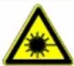
Description of the test instrument
text_image
MAX MIN AVG REL TEST 8.8.8.8 SPOLE SPOLE READ VERSION V kΩ 88 PASS MEMO HEADLINE Rθ SPOLE SPOLE VY RESET ENTER REL 9 10 11 12 13 4 3 2 1 E P/S C/H 14 15 16(1) Rotary switch
(2) APS button
(3) LIGHT button
(4) CLEAR button
(5) LCD
(6) READ button
(7) MEMO button
(8) MEASURE button
(9) ▲utton
(10) MAX/MIN/AVG button
(11) ENTER button
(12) REL button
(13) Button
(14) Jack E
(15) Jack P/S
(16) Jack C/H
Switch between measurement of the earth voltage and two-pole or three-pole measurement of the earth resistance.
Activates or deactivates the automatic deactivation function.
Activates or deactivates the background illumination.
Deletes data.
Displays the measured data and various symbols.
Displays the measured data.
Saves the measured data
Activates or deactivates the measurement of the resistance.
Selects a memory cell to save the measured data
Switches between the measurement of maximum, minimum and average.
Confirms the saving or reading out of data.
Selects relative measurement.
Selects a memory cell to save the measured data
Connects the measurement pole.
Connects the auxiliary earthing rod
Connects the auxiliary earther
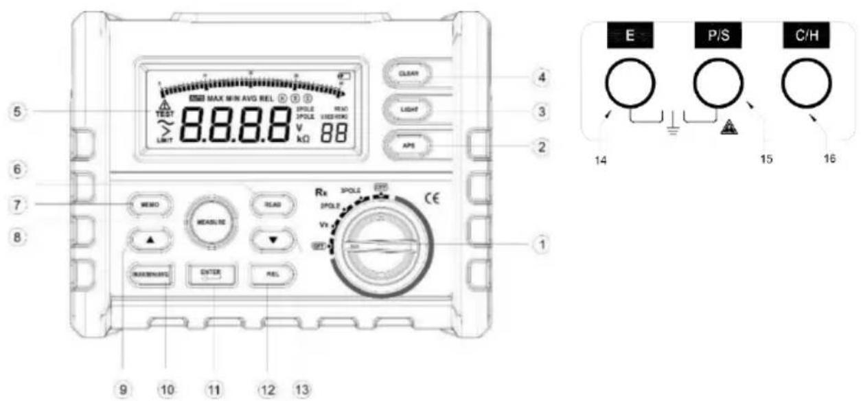
LC-Display
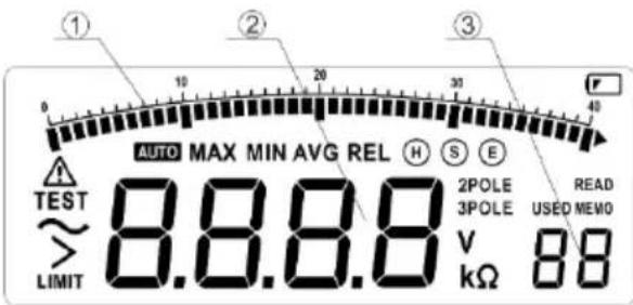
text_image
① 10 20 30 40 AUTO MAX MIN AVG REL H S E TEST ~ > 8.8.8.8 2POLE READ LIMIT 2POLE USED MEVO v kΩ 88(1) Bar graph display
(2) Display of the measured data
(3) Display of the memory cell used.
Description of the symbols on the LCD:
| TEST: | A test is performed | |
| >LIMIT: | A limit value is exceeded | |
| MAX: | Maximum | |
| MIN: | Minimum | |
| AVG: | Average | |
| REL: | Relative measurement | |
| READ: | Saved data is displayed | |
| MEMO: | Data are saved | |
| USED: | Data in memory | |
| 2POLE: | Two-pole resistance measurement | |
| 3POLE: | Three-pole resistance measurement | |
| V: | Volt (voltage) | |
| KΩ: | Ohm (resistance) | |
| With active symbol, automatic deactivation is activated | ||
 | With active symbol, the battery level is low | |
 | Identification of the jacks | |
 | AC current is used | |
 | Warnings | |
Specifications
Air temperature: 23 ± 5 °C Relative air humidity: < 75 %
Range specifications
| Range | Accuracy | |
| Earth resistance | 0 – 29.99 Ω | ± 2 % of read-off value+ +6 digits |
| 30.0 – 99.9 Ω | ± 3 % of read-off value+ +3 digits | |
| 100 – 999 Ω | ± 3 % of read-off value+ +3 digits | |
| 1.00 k – 4.00 kΩ | ± 3 % of read-off value+ +3 digits | |
| Earth voltage | 0 V – 200 V (50/60 Hz) | ± 1 % of read-off value+ +5 digits |
Test procedure
Measurement of the earth resistance is performed via constant current conversion with a test current frequency of c. 800 Hz and a current of 3 mA.
The earth voltage is measured via mean value rectification.
Operation

Danger
Do not apply a voltage higher than AC 230 V to the test port when measuring the earth voltage.
When measuring the earth resistance, a voltage of c. 50 V is measured between connections
E and S or the connections E and C. Protect yourself against an electric shock.
Check the battery charge before using the measuring instrument. If the display shows after activation of the measuring instrument, it is necessary to replace the batteries (see chapter "Changing the batteries").
Measuring the earth voltage
Turn the rotary switch to VE. Connect the test leads to the jacks E and S and connect the other ends of the test leads with the voltage supply. The presence of voltage is registered on the LC display.
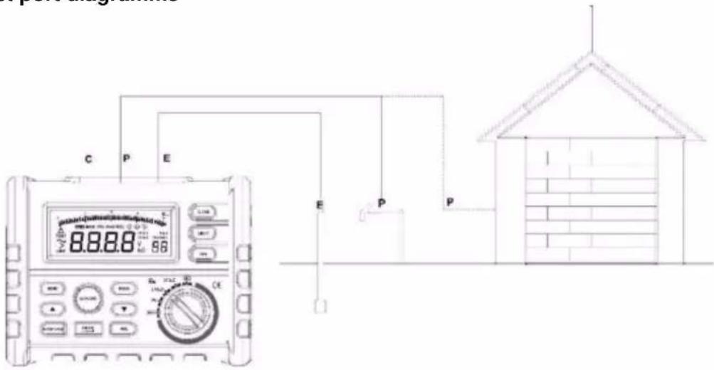
Two pole-measurement of the earth resistance
Instead of the auxiliary earthing rod, this procedure uses the earth poles present as an auxiliary earthing rod, such as any metal in the ground (water lines etc.) the joint earth of the mains power supply or lightening conductors of high buildings.
(1) Test port diagramme
text_image
C P E 8.8.8.8 E P P 100V 20Hz 150V 30Hz CE A B C D E F G H I J K L M N O P Q R S T U V W X Y Z(2) Measuring the earth voltage
Before measuring the earth resistance, it is first necessary to measure any earth voltage present, as voltages over 10 V can cause serious errors is the measurement of the earth resistance. In this case, disconnect the measurement object from the power supply and wait until the earth voltage falls.
(3) Measuring the earth resistance
Turn the rotary switch to 2POL and press the MEASURE button. The button illuminates during the active measurement. A signal tone sounds after the measurement has come to an end and the LED extinguishes. The data are displayed automatically.
Caution:
If > LIMIT 4000 Ω is displayed on the LCD, this means that the auxiliary resistance of the auxiliary earthing rod is so high that the current cannot flow through the measuring instrument. Check whether the test leads have disconnected and the level of the earth resistance of the auxiliary earthing rod.
(4) Measured value
Re, the value of the earth resistance measured with the two-pole procedure corresponds to the sum of re, the earth resistance of the earthing rod, and RX, the actual earth resistance of the measured object. Thus RX = Re - re, the actual resistance of the mass object corresponds to Re minus re.
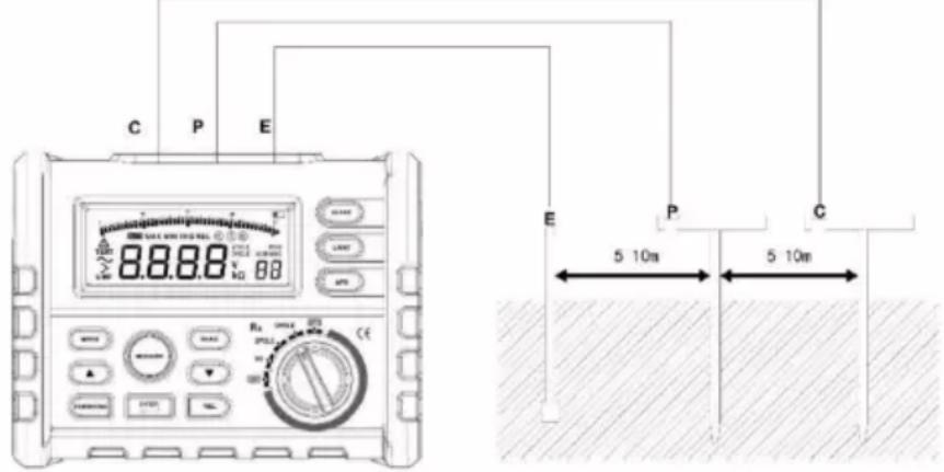
Three pole-measurement of the earth resistance
The measuring instrument uses the voltage drop procedure for measurement. The earth resistance RX is determined by allowing the nominal current I to flow between the measurement object E (the earthing rods) and the current pole C and then measuring V, the voltage difference between E and the voltage pole P.
(1) Connect the test leads to the measuring instrument in the following fashion
text_image
C P E 88.88 V 80 E P C 5 10m 5 10mPlace the auxiliary earthing rods P and C deep in the soil in a perpendicular manner with a clearance of 5 to 10 metres. Connect the test leads (black, red and green) from the connections E, P and C with the measurement object and connects with the auxiliary earthing rods P and C.
Caution:
The ground around the auxiliary earthing rod must be damp Dampen any dry loam, sand or grit before the measurement. Should the floor surface be cement, place the auxiliary earthing rod on the floor, wetten it and cover with a damp cloth.
(2) Measuring the earth voltage
Before measuring the earth resistance, it is first necessary to measure any earth voltage present, as voltages over 10 V can cause serious errors in the measurement of the earth resistance. In this case, disconnect the measurement object from the power supply and wait until the earth voltage falls.
(3) Measuring the earth resistance
Turn the rotary switch to 3POL and press the MEASURE button. The button illuminates during the active measurement. A signal tone sounds after the measurement has come to an end and the LED extinguishes. The data are displayed automatically.
Caution:
If > LIMIT 4000 Ω is displayed on the LCD, this means that the auxiliary resistance of the auxiliary earthing rods is so high that the current cannot flow through the measuring instrument. Check whether the test leads have disconnected and the level of the earth resistance of the auxiliary earthing rod. Should the test leads be turned together or in contact during measurement, this will produce measurement errors. Ensure that the test leads are not in contact during measurement. Too high an auxiliary resistance results in unacceptable measurement errors. Ensure that the auxiliary earthing rods P and C are deeply in the damp soil and are have been connected correctly.
Saving data
The measuring instrument can save up to 100 groups of measured data which are retained after interruption of the power supply.
(1) Working in standby, press "MEMO" to access the data storage display. MEMO will illuminated on the bottom right-hand of the LCD. If the available memory is already full, USED will illuminate. Press "MEMO" again to leave data saving.
(2) Pressing "ENTER" for a short time enables you to move between the "1" and "10" positions; you can page through using "for".
(3) Press “ENTER” for 5 seconds to save a data group. Any data already saved on the selected memory will be overwritten.
Reading out data
Reading out data enables you to check of the earlier measurements saved in the measuring instrument.
(1) Working in standby, press "MEMO" to access the data storage display. MEMO will illuminated on the bottom right-hand of the LCD. If the available memory is already full, USED will illuminate. Press "MEMO" again to leave data saving.
(2) Pressing "ENTER" for a short time enables you to move between the "1" and "10" positions; you can page through using "for".
(3) Press "ENTER" for 5 seconds to read out a saved a data group.
REL – Relative measurement
Relative measurement is only available when measuring the earth resistance. Pressing REL switches between normal and relative measurement.
(1) In Relative measurement mode, the symbol "REL" is displayed on the LCD and the current measured value is saved for later use. In the following relative measurement, the LCD shows the difference between the input value and the reference value: displayed measured value = input value - reference value.
(2) It is not possible to change into REL mode during a running normal earth resistance measurement.
(3) It is not possible to change into REL mode whilst data is being read out or saved.
(4) It is not possible to change into REL mode if the current measured value lies over the limit value.
MAX/MIN/AVG measurement
Pressing the MAX/MIN/AVG button switches between the measuring modes Maximum, Minimum, Average or Normal. The corresponding symbol is displayed on the LCD.
(1) If MAX has been selected, the LCD shows the maximum of all data.
(2) If MIN has been selected, the LCD shows the minimum of all data.
(3) If AVG has been selected, the LCD shows the average of all data.
Deleting data
The data can be deleted if READ or MEMO have been pressed. Pressing CLEAR briefly deletes the data on the current memory position, prolonged pressing (c. 5 sec) deletes all saved data.
Backlighting
The background illumination is switched on or off by pressing LIGHT and switches off automatically 15 seconds after activation.
Automatic deactivation
The automatic deactivation function is activated or deactivated by pressing APS. When the automatic deactivation function is active, the symbol is displayed on the LCD. If the automatic deactivation function is active, a signal tone will sound after 15 minutes of inactivity and the measuring instrument is switched into resting state. The device can be reactivated by pressing any button.

The rotary switch must be set to "OFF" if the measuring instrument is not used for a longer period.
Replacing the battery

Danger
Do not change the batteries if the measuring instrument is damp.
Do not change the batteries whilst the measuring instrument is being used. Before changing the batteries, switch off the measuring instrument and disconnect the test leads and the earthing rods to avoid an electric shock.

Caution
Do not mix new and old batteries.
Comply with the polarity of the batteries.
Unscrew and remove the cover of the battery compartment.
Replace the batteries whilst complying with the polarity.
Replace the cover of the battery compartment and screw down.
Technical data
| Display | LC display with backlighting |
| Overvoltage category | CAT III 300 V |
| Earth resistance | 0 - 4000 Ω |
| Earth voltage | 0 – 200 V (50/60 Hz) |
| Storage temperature | 10 °C to 50 °C RH < 85 % |
| Operating temperature | 0 °C to 40 °C RH < 85 % |
| Voltage supply | 6 x 1.5 V Type AA Mignon |
| Weight | 3.45 kg |
| Dimensions | 330 x 125 x 80 mm |
| Accessories | 3 test leads (one 15 m long red line, one 10 m long green line and a 5 m long black line), 2 auxiliary earthing rods. |
Table des matières
Consignes 28
Cd = Cadmium, Hg = mercure, Pb = plomb.
text_image
C P E 88.88 V 88 E P C 5 10m 5 10mtext_image
C P E 8888 E P C 5 10m 5 10mtext_image
C P E 88.88 V 88 E P C 5 10m 5 10mMAX/MIN/AVG-meting 72
Cd = cadmium, Hg = kwik, Pb = lood.
text_image
C P E 8888 88 E P P(2) Meting van de aardingsspanning
text_image
C P E 8.888 kΩ 88 E P C 5 10m 5 10mtext_image
Testboy® GmbH, Germany Stands For Quality Since 1953Testboy GmbH Tel: 0049 (0) 4441 / 89112-10
Germany info@testboy.de