DL-250V - Measuring equipment VOLTCRAFT - Free user manual and instructions
Find the device manual for free DL-250V VOLTCRAFT in PDF.

| Product type | Portable data logger for voltage measurement |
| Brand | VOLTCRAFT |
| Model | DL-250V |
| Order no. | 2203101 |
| Measuring range | 0.00 - 30.00 V |
| Resolution | 0.1 V |
| Accuracy | ±0.5 % of full scale |
| Memory capacity | 31,320 measured values |
| Sampling rate | From 10 seconds to 24 hours (adjustable) |
| Display | Backlit LCD display |
| Connectivity | USB 2.0 (USB stick type) |
| Power supply | 1 CR2450 3 V button cell battery |
| Battery life | Approx. 1 year (sampling once per minute) |
| Dimensions (L x H x D) | Approx. 37 x 86 x 19 mm |
| Weight | Approx. 59 g |
| Operating conditions | 0 to 50 °C, <80 % RH (non-condensing) |
| Storage conditions | -10 to +60 °C, <70 % RH (non-condensing) |
| Protection | Against dust and water jets (with protective cover closed) |
| Configuration | Via Voltsoft software or dedicated website |
| Report creation | Automatic PDF report with chart |
| Main functions | Continuous recording, LED alerts, multiple start/stop modes, min/max display, alarm pause function |
| Maintenance and cleaning | Clean with a dry antistatic cloth; do not immerse |
| Safety instructions | Do not use in explosive atmosphere, observe battery polarity, protect from shocks and excessive humidity |
| Package contents | Data logger, USB protective cap, CR2450 button cell battery, CD with manual |
Frequently Asked Questions - DL-250V VOLTCRAFT
User questions about DL-250V VOLTCRAFT
0 question about this device. Answer the ones you know or ask your own.
Ask a new question about this device
Download the instructions for your Measuring equipment in PDF format for free! Find your manual DL-250V - VOLTCRAFT and take your electronic device back in hand. On this page are published all the documents necessary for the use of your device. DL-250V by VOLTCRAFT.
USER MANUAL DL-250V VOLTCRAFT
GB Operating Instructions
Data logger
Item No. 2203098 (DL-260A: Current)
Item No. 2203101 (DL-250V: Voltage) Page 29 - 55
F Notice d'emploi
- Introduction......30
- Symbol explanation, markings....31
- Intended use....31
- Delivery content....32
- Features and functions 32
- Safety instructions ....33
- Operating elements 34
- LED status display 36
- Initial operation ...... 37
a) Protective cap 37
b) Connect to the computer 37
c) Disconnect from the computer....37
d) Choose start/stop mode 37
e) Define date and time during configuration....37
f) Button ENTER....37
- Before first use....38
a) Protection foil....38
b) Insert/replace battery....38
- Configuration 39
a) Install software....39
b) Software functions overview....39
c) Create configuration file by software and load the configuration file created from software onto data logger 40
d) Perform configuration setting on the website 40
e) Create configuration file by website....44
f) Load configuration file created on the website onto the data logger 44
g) Review configuration settings....44
- Overview of operation modes, settings and LC Display indications 45
a) Operation modes and settings....45
b) LC display indication....47
- Logging data....49
a) Enter function menu 49
b) Start recording....49
Page
c) Stop recording....49
d) Show remaining time until start/end of recording 49
e) Activate/deactivate limit alarm pause function....50
f) Read maximum/minimum measurements....50
- Create PDF Report....51
- Delete data ....51
- Upgrade firmware 52
- Reset to default firmware....52
- Troubleshooting....53
- Maintenance and cleaning....54
- Disposal....54
a) Product....54
b) Batteries 55
- Technical data....55
1. Introduction
Dear customer,
By purchasing a Voltcraft® product, you have made an excellent decision, for which we wish to thank you.
Voltcraft ^® – This name stands for outstanding quality products in the fields of measurement, charging and network technology, products that stand out due to their professional competence, exceptional performance and permanent innovation.
Whether you are an ambitious electronics hobbyist or a professional in the field, with a product from the Voltcraft ^® family, you have the optimum solution at hand at all times, even for the most challenging tasks. And it gets even better: We make the sophisticated technology and reliable quality of our Voltcraft ^® products available to you at a nearly unbeatably low price-performance ratio. In this way, we create the basis for lengthy, good and successful cooperation.
We hope you will enjoy your new Voltcraft® product!
All company names and product names are trademarks of their respective owners. All rights reserved.
If there are any technical questions, please contact:
www.conrad.com/contact
2. Symbol explanation, markings

An exclamation mark in a triangle indicates important notes in these operating instructions that must be strictly observed.
The arrow symbol alerts the user to the presence of important tips and notes on using the device.

This device is CE compliant and fulfills all applicable European guidelines.
3. Intended use
The battery-operated portable data loggers DL-260A measures current, and DL-250V measures voltage.
Measuring data is recorded automatically at adjustable sampling rates from 1 minute to 24 hours. At most 31320 measuring values can be saved. Measured values can be immediate read on the LC display. The data logger can be configured online or by the included software.
The product is connected to a computer like a regular USB memory stick and read out there. It automatically generates a graphical report in PDF format. A long-life lithium battery ensures a long recording time.
With attached protective cap, the product is dust tight and jet water-protected and can be used indoors and outdoors. Do not use the device if the housing is not completely shut or if the protection cap is not attached properly.
Measuring under adverse ambient conditions like dust and flammable gasses, vapours or solvents is not admissible. The safety instructions must be followed unconditionally!
This product fulfils European and national requirements related to electromagnetic compatibility (EMC). CE conformity has been verified and the relevant statements and documents have been deposited at the manufacturer.
This product complies with the statutory, national and European requirements.
For safety and approval purposes, you must not rebuild and/or modify this product. If you use the product for purposes other than those described above, the product may be damaged. In addition, improper use can cause hazards such as short circuiting, fire, etc. Read the instructions carefully and keep them for future reference. Make this product available to third parties only together with its operating instructions.
4. Delivery content
• Data logger incl. USB protective cap
• 3 V button cell, type CR2450
- User manual on CD
Up-to-date operating instructions
Download the latest operating instructions via the link www.conrad.com/downloads or scan the QR code. Follow the instructions on the website.

5. Features and functions
- Portable data logger with LC Display
- Compact USB stick design
-
Measurements:
-
DL-260A: Current (mA)
- DL-250V: Voltage (V)
• Maximum and minimum readings
- Logging timer
- Configuration via website or by software
• Automatic generation of PDF report with graph
- Adjustable sampling rate from 10 seconds to 24 hours

Read the operating instructions carefully and especially observe the safety information. If you do not follow the safety instructions and information on proper handling in these operating instructions, we assume no liability for any resulting personal injury or damage to property. Such cases will invalidate the warranty/guarantee.
- The device is not a toy. Keep it out of the reach of children and pets.
- Do not leave packaging material lying around carelessly. These may become dangerous playing material for children.
- Protect the product from extreme temperatures, direct sunlight, strong jolts, moisture, flammable gases, vapours and solvents.
- Do not place the product under any mechanical stress.
- If it is no longer possible to operate the product safely, take it out of operation and protect it from any accidental use. Safe operation can no longer be guaranteed if the product:
- is visibly damaged,
- is no longer working properly,
- has been stored for extended periods in poor ambient conditions or
- has been subjected to any serious transport-related stresses.
- Please handle the product carefully. Jolts, impacts or a fall even from a low height can damage the product.
- Also observe the safety and operating instructions of any other devices which are connected to the product.
- Do use the device in rooms or at unfavourable ambient conditions in which there may or could be combustible gases, vapours or dust. Avoid an operation near:
- strong magnetic or electromagnetic fields
- transmitting aerials or HF generators
- since this could affect the measurement.
- The product is only protected against ingress of solid foreign bodies with a diameter > 1 mm when the protective cap is properly fastened and the housing is completely closed. The data logger must not be operated with the battery compartment open or without the protective cap..
- Battery must be kept out of reach of children. Do not leave battery lying around, as there is risk, that children or pets swallow it.
- Correct polarity must be observed while inserting the battery.
- Battery should be removed from the device if it is not used for a long period of time to avoid damage through leaking. Leaking or damaged battery might cause acid burns when in contact with skin, therefore use suitable protective gloves to handle corrupted battery.
- Do not disassemble, short-circuit or throw battery into fire. Never recharge non-rechargeable battery. There is a risk of explosion!

- Consult a professional if you require assistance with product operation, safety or connection.
- Maintenance work, adjustments and repairs may be carried out only by a professional or at a specialist workshop.
Should you have questions concerning correct product connection or operation, or should other questions arise that this user manual does not address, please do not hesitate to contact our technical support or a third-party professional.
7. Operating elements
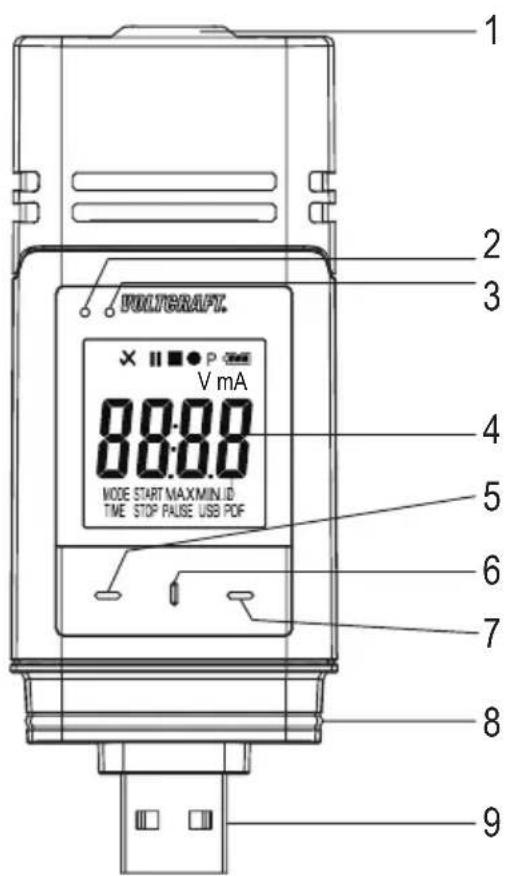
text_image
PULYGRAFT. V mA MODE START MAXMIN ID TIME STOP PAUSE USB PDF
text_image
101 Sensor openings
2 Red LED control light
3 Green LED control light
4 LC display
5 Button "DOWN"
6 Button "RELEASE BATTERY COMPARTMENT"
7 Button "ENTER"
8 Rubber seal
9 USB plug
10 Protective cap
Symbols in the LC display
| Symbol Meaning | |
| √ | Alarm indicator: Measured values are within the limits defined during configuration. |
| No high/low alarm is set. | |
| × | Alarm indicator: Measured values are exceeding the limits defined during configuration. |
| ■ | Recording has been stopped. |
| ● | Recording in progress. |
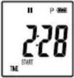
| II | Recording has been paused. |
| P | Device is ready to record: Device is configured, and recording not started yet. It will disappear once the data logger records. |
| Battery symbol: Full battery capacity | |
| Battery symbol: Sufficient battery capacity | |
| Battery symbol: Low battery capacity, replace the battery | |
| mA Unit for current | |
| V Unit for voltage | |
| ID Logger ID | |
| MAX/MIN Maximum/minimum measurement | |
| USB Connected to computer. | |
| USB PDF Connected to computer and generating PDF report. | |
| PAUSE Indicates that the limit alarm pause function is enabled. | |
| MODE START | Indicates that a start mode has been chosen. It will be shown before recording starts. |
| MODE STOP | Indicates that a stop mode has been chosen. It will be shown before recording ends. |
| TIME START | Indicates remaining time before start of recording. |
| TIME STOP Indicates remaining time until end of recording. | |
| Strt | Ready to start recording by holding button ENTER (7) for few seconds. (Select “START UPON KEYPRESS” as “RECORD START CONDITION” during configuration.) |
| Stop | Recording can be stopped by holding button ENTER (7) for few seconds. (Select “STOP BUTTON” as “STOP STYLE” during configuration.) |
| on | Ready to activate limit pause function by holding button ENTER (7) for few seconds. |
| _oFF | Ready to deactivate limit pause function by holding button ENTER (7) for few seconds. |
| d | Days, unit for remaining time. (If the remaining time is below one day, remaining time is shown in HH:MM format.) |
| _up | Ready to upgrade firmware. |
| _ol | Measurement error |
| Measured values are beyond the measuring range. | |
| _Err1 | Configuration error. An error occurred during configuration. Repeat the configuration process. |
8. LED status display
| LED indicator Description | |
| Green LED control light (3) is flashing. | Measured value(s) are within the configured limits of low and high alarm. |
| Red LED control light (2) is flashing. | Memory is full. |
| Measured value(s) are exceeding configured limits of low and high alarm. | |
| In mode “START UPON KEYPRESS” or “STOP TIME” recording has been terminated. (In order to start recording again, re-configure data logger.) | |
| In mode “START UPON KEYPRESS”, data logger is ready to start recording. (In order to start recording hold button ENTER (7) pressed for few seconds.) | |
| Red LED control light (2) is continuously on. | Data logger is generating PDF report. |
| Green LED control light is flashing twice. | Configuration was successful. |
| Firmware has been updated successfully. | |
| No LED light is on. LED-alarm was disabled during configuration. | |
9. Initial operation
a) Protective cap

The data logger is only dust tight and jet water protected with attached protective cap (10) and rubber seals (8). This protection allows permanent logging operation in damp rooms and outdoors.
- Only remove the protective cap for replacing the battery or reading the data on the computer.
- Remove the protective cap by pulling it off from the data logger. The protective cap fits tightly due to the rubber seal (8).
- Place the protective cap tightly back onto the data logger.
b) Connect to the computer
- Remove the protective cap (10) from the data logger.
- Connect the data logger to an available USB port of your computer.
- The computer recognizes the new hardware. The model type of your data logger appears as a mass storage device on your computer.
c) Disconnect from the computer
- Eject the data logger from your computer and remove it.
- Place the protective cap back on the data logger.
d) Choose start/stop mode
- Choose start mode from "RECORD START CONDITION" during configuration.
- Choose stop mode from "STOP STYLE" during configuration.
e) Define date and time during configuration
- Select month, year and time with date picker and time sliders. The time will be shown as “TIME” in HH:MM:SS format. Confirm with “DONE”. Date and time settings are displayed in the corresponding fields.
- Alternatively, click "NOW", if you require an immediate start of logging. Actual date and time - as per locally set on your computer - will be filled automatically into field "START TIME"/"STOP TIME".
f) Button ENTER
- Press button ENTER (7) to switch between maximum and minimum reading.
- Press and hold button ENTER (7) for few seconds to start/stop logging or activate/deactivate pause function.
10. Before first use
a) Protection foil
- Remove the protection foil from the LC display (4).
b) Insert/replace battery
- Install the battery before first-time use or replace the battery when the battery symbol “☐” appears in the LC display.
→ Removing and replacing batteries does not delete data or settings.
- Remove the protective cap from the data logger.
- Press and hold the button release battery compartment (6) and pull out the logger unit from the housing. The housing fits tightly due to the second rubber seal (8).
- Release the button release battery compartment.
- The battery compartment is on the back of the logger unit. Insert a new and suitable battery (see "21. Technical data" on page 55) into the battery compartment observing correct polarity (positive/+ and negative/-).
- Slide the logger unit back into the housing. Ensure that the LC display matches to the LCD window of the housing.
- Place the protective cap back onto the data logger.

The data logger performs best at room temperature. If the item is used at extremely low temperatures, the battery life is reduced. In such case, you can reduce power consumption of the data logger in order to prolong the operation time as following
- disable LC Display
- disable LED alarm
- set a longer sampling rate
For details refer to chapter "11. Configuration" on page 39
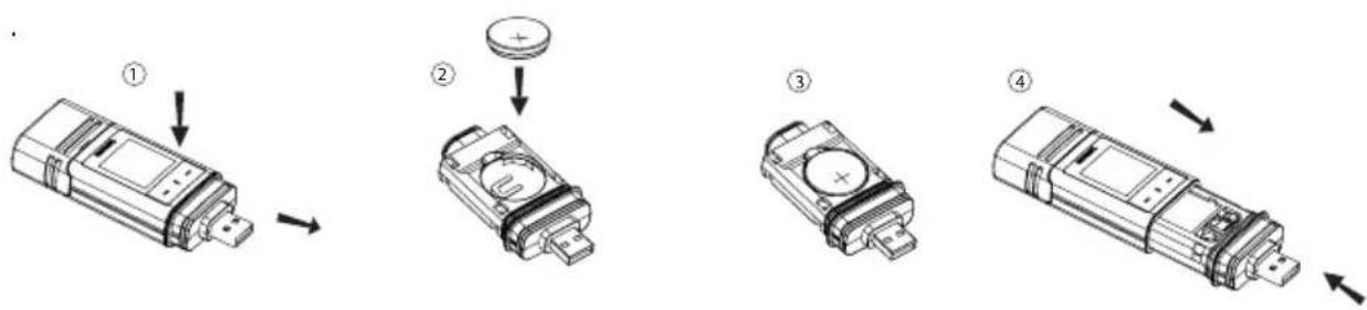
flowchart
graph TD
    A["Device with ①"] --> B["Step ②"]
    B --> C["Step ③"]
    C --> D["Step ④"]
11. Configuration
After inserting a battery, configure the data logger either by software or by website. Select logging parameters like sampling rate, start time, recording time, pause function, LED flash interval, enable/disable LC display and PDF report settings.
Configuration terminologies and commands may differ between software and website.
The following instructions and explanations are based on the terminologies and commands found on the configuration website.
After creating the configuration file, copy it to the data logger!
a) Install software
- Insert the software CD into the DVD drive of your computer.
- The installation will start automatically. If not, go to your DVD drive directory, and open the installation file "autorun.exe".
- Select your desired language German, French or English.
- Follow the on-screen instructions to complete the installation. Depending on your operating system a restart may be required.
- For further information, refer to the operating instructions on the CD provided (section 3).
- The enclosed software is the Voltsoft standard edition. The professional version (Voltsoft Data Logger, No. 10133tt3) is an optional item which you can purchase separately. If you purchase the professional version, you will receive a license key. Follow the steps in the Voltsoft operating instructions, to register and upgrade to the professional version.
b) Software functions overview
| Standard Professional | |
| User Management | |
| Email Management | |
| General Settings | |
| Language Preference | |
| Email Template | |
| Device Management (Add/Remove) | |
| Custom Graph |
c) Create configuration file by software and load the configuration file created from software onto data logger
- Connect the data logger to your computer.
- Start the Voltsoft software and follow the operating instructions in the software manual (section 6 and choose your supported device).
- Disconnect the data logger from your computer.
d) Perform configuration setting on the website
There are 2 options to open the configuration website:
- Open http://datalogger.voltcraft.com/ConfigBuilder/index.jsp in a browser.
- Connect the data logger to your computer. Open the data logger drive on your computer. Click on the link "Configuration Website.html" to open the configuration website.
Main Screen - Overview
| General Settings | Choose the desired language for the website by clicking on the corresponding flag. |
| Select the model of your data logger. The model name is mentioned on the packaging and/or product. Chosen model type will be highlighted in red. | |
| MEASUREMENT options | Here you select the logging parameters for your data logger.For further instructions, please refer to “MEASUREMENT” options - “BASIC SETTING” on page 41 and “MEASUREMENT” options - “ALARM SETTING” on page 42. |
| PDF REPORT OPTIONS | Here you define the content and name of the PDF report.For further instructions, please refer to “PDF REPORT OPTIONS” on page 43. |
| Other settings | Here you can create the configuration file, load a previous setting or restore entries to default.For further instructions, please refer to “Other settings” on page 44. |
"MEASUREMENT" options - "BASIC SETTING"
Select "MEASUREMENT" in the navigation bar and enter settings in "BASIC SETTING".
| LOGGER ID | Logger ID is a four digit identifier. Enter a number between 0000 and 9999 e.g. 0014. Use different logger IDs to identify data loggers with e.g. different configuration file for different usage. |
| RECORD START CONDITION | Select one of the following options to determine when data logger starts recording. Each option has a default stop setting. |
| “IMMEDIATELY UNTIL MEMORY FULL”: Data logger starts recording data immediately until the memory is full. | |
| “START UPON KEYPRESS”: Data logger starts recording after holding button ENTER (7) pressed for few seconds. Data logger stops recording until memory is full. | |
| “START UPON START TIME”: Data logger starts recording at a defined date and time until the memory is full. | |
| “START/STOP TIME”: Data logger starts and stops recording data at a defined date and time. | |
| RECORD START CONDITION | “CIRCULAR LOGGING”: Data logger starts recording immediately and circularly. The newest data overwrites the oldest data. It stops recording/logging once the battery is depleted or “CIRCULAR LOGGING” has been replaced by another “RECORD START CONDITION” during configuration. |
| STOP STYLE | Select one of the following options to determine when data logger ends recording. |
| “NONE”: No stop condition is specified. Data logger stops recording based on the “RECORD START CONDITION” setting. | |
| “STOP BUTTON”: Data logger stops recording after holding button ENTER (7) pressed for few seconds. | |
| “AFTER PDF CREATED”: Data logger stops recording after PDF report is generated. | |
| START TIME Define date and time when to start recording data. | |
| STOP TIME Define date and time when to stop recording data. | |
| START DELAY MINUTES | Define delay time of immediate start of recording. |
| SAMPLING RATE | Define how frequent the data logger measures and records data in “MINUTES” or “HOURS”.→When using the data logger at extremely low temperatures, choose a longer sampling rate to decrease power consumption and to prolong the battery life. |
| RECORDING TIME | This value is automatically calculated based on the sampling rate and cannot be set by the user. |
| LED FLASH INTERVAL | Select how fast the LED control lights (2,3) shall flash. Choose an interval of 5, 10, 15, 20, 25 or 30 seconds. |
| ENABLE DISPLAY | Remove the checkmark from the check box to turn off the LC display, or check the checkbox to turn on the LC display.When using the data logger at extremely low temperatures, choose a longer sampling rate to decrease power consumption and to prolong the battery life. |
"MEASUREMENT" options - "ALARM SETTING"
Configure alarm settings in the "Measurement" tab:
| ENABLE LED ALARM | The LED alarm indicates when a measured value is outside the defined range.To disable the LED alarm, remove the checkmark in the checkbox.To enable the LED alarm, check the checkbox.→When using the data logger at extremely low temperatures, disable the LED alarm to decrease power consumption and to prolong the battery life. |
| LIMIT PAUSE FUNCTION | During recording, the limit alarm can be suspended.Select “ENABLE” or “DISABLE” to enable/disable the pause function.→Pause function will not stop the recording. |
| LOW ALARM/ HIGH ALARM | Select parameter(s) by checking parameter checkboxes and specify the low and high alarm in numbers.→The red LED control light (2) is flashing, when measured value is outside of the defined range of low and high alarm value. |
"PDF REPORT OPTIONS"
Select "PDF Report Options" in the navigation bar and enter settings to define content of the PDF report.
| LANGUAGE | Choose the language, in which the PDF report shall be shown, from the selection box. |
| PDF FILE NAME | Click on “INSERT NAME” to define the pattern of the file name.A new window “PLEASE CHOOSE THE NAME PATTERN BELOW” opens. Choose the required elements (OWNER/SERIAL ID/MODELNAME/DATE/TIME/LOCATION) and their order.Up to 6 elements can be chosen. Chosen elements appear in the field “FILE NAME”.Press “CLEAR” to delete all chosen elements. The field “FILE NAME” is empty again.Press “X” to save the file name pattern and close this window. |
| DATE FORMAT Select your preferred date format from menu. | |
| TIME FORMAT Select between 12 hour or 24 hour format. | |
| OWNER Key in the owner’s name. | |
| LOCATION Key in the location’s name e.g. the name of the location where you will record. | |
| REPORT TITLE Enter a report title, which will be shown on the PDF report. | |
| USER TEXT Enter some remarks or additional information if needed. | |
Other settings
| CREATE CONFIGURATION | Create the configuration file and save it to your computer and install it to the data logger. For further instructions, please refer to”e) Create configuration file by website” on page 44 and “f) Load configuration file created on the website onto the data logger” on page 44). |
| LOAD SETTINGS | Load a previous configuration file - if any - to check the details of that file on the website.A new window pops up.Choose a configuration file, which you have created and saved on the computer earlier. |
| DEFAULT Reset the | settings to default values and setting. |
e) Create configuration file by website
- After performing configuration settings, select "CREATE CONFIGURATION" to download the configuration file to your computer.
- A new window appears to change the configuration file name. Default name is "Setlog". If needed, change the name of the file.
- Confirm the file name by clicking "CREATE CONFIGURATION". Your configuration file has been downloaded/ imported to your computer.
f) Load configuration file created on the website onto the data logger
- Remove protective cap from the data logger.
- Connect the data logger to your computer.
- Drag and drop the configuration file from the download folder of your computer to the data logger folder to execute the configuration.
- The green LED control light (3) flashes twice, when the configuration file is successfully installed on the data logger.
- When the data logger is configured, disconnect the data logger from your computer.
g) Review configuration settings
- Start mode is based on the configuration setting "RECORD START CONDITION".
- Stop mode is based on the configuration "STOP STYLE".
- You can check which start mode is active, by loading the existing configuration file into the web interface, in the PDF report or by entering the function menu of the data logger.
- You can check which stop mode is active, by loading the existing configuration file into the web interface or by entering the function menu of the data logger.
- For further instructions regarding loading the existing configuration settings, please refer to "Other settings" on page 43.
- For further instructions regarding entering the function menu, please refer to "a) Enter function menu" on page 49.
12. Overview of operation modes, settings and LC Display indications
a) Operation modes and settings
For performing following configuration settings, please refer to "Perform configuration setting on the website" on page 40.
| Mode 1 | |
| Function Logging starts immediately. | |
| Setting Select "IMMEDIATELY UNTIL MEMORY FULL" as "RECORD START CONDITION". | |
| Mode 2 | |
| Function Logging starts immediately. | |
| Setting Select "IMMEDIATELY UNTIL MEMORY FULL" as "RECORD START CONDITION". | |
| Mode 3 | |
| Function Logging starts immediately. | |
| Setting Select "IMMEDIATELY UNTIL MEMORY FULL" as "RECORD START CONDITION". | |
| Mode 4 | |
| Function Logging starts when button ENTER (7) is pressed for few seconds. | |
| Setting Select "START UPON KEYPRESS" as "RECORD START CONDITION". | |
| Mode 5 | |
| Function Logging starts and stops when button ENTER (7) is pressed for few seconds. | |
| Setting Select "START UPON KEYPRESS" as "RECORD START CONDITION". | |
| Mode 6 | |
| Function Logging starts when button ENTER (7) is pressed for few seconds. | |
| Setting Select "START UPON KEYPRESS" as "RECORD START CONDITION". | |
| Mode 7 | |
| Mode 7 | |
| Function Logging starts at defined time. | |
| Setting Select "START UPON START TIME" as "RECORD START CONDITION". | |
| Mode 8 | |
| Function Logging starts at defined time. | |
| Setting Select "START UPON START TIME" as "RECORD START CONDITION". | |
| Mode 9 | |
| Function Logging starts at defined time. | |
| Setting Select "START UPON START TIME" as "RECORD START CONDITION". | |
| Mode 10 | |
| Function Logging starts and stops at defined time. | |
| Setting Select "START/STOP TIME" as "RECORD START CONDITION". | |
| Mode 11 | |
| Function Logs data immediately and circularly. | |
| Setting Select "CIRCULAR LOGGING" as "RECORD START CONDITION". | |
| Mode 12 | |
| Function Logs data immediately and circularly. | |
| Setting Select "CIRCULAR LOGGING" as "RECORD START CONDITION". | |
| Mode 13 | |
| Function Logs data immediately and circularly.Should you wish an additional stop mode you choose:Logging stops after PDF report generation. | |
| Setting Select “CIRCULAR LOGGING” as “RECORD START CONDITION”.Select “AFTER PDF CREATED” as “STOP STYLE”. |
- For mode 1 to 13, you can apply an additional function to delay the logging start time. Enter minute(s) value in "START DELAY MINUTES" during configuration setting.
b) LC display indication
- Some settings do not have any indication on LC display. In order to review settings, please refer to "g) Review configuration settings" on page 44.
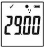
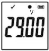
- If there is not any display indicator or once the data logger starts/stops recording, the latest measurement is shown on display.
| DL-260A: Current (mA) | DL-250V: Voltage (V) |
 |  |
| Mode Start mode Stop mode | Remarks | ||
| 1 | no display indicator | not applicable | When memory is full, red LED control light (2) is flashing. |
| 2 no display indicator | 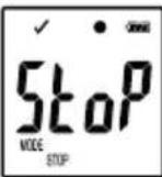 | Stop recording by holding button ENTER (7) pressed for few seconds. | |
| 3 no display indicator | no display indicator | ||
| 4 | 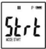 | not applicable | When memory is full, red LED control light (2) is flashing.Start recording by holding button ENTER (7) pressed for few seconds. |
| 5 | 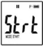 | 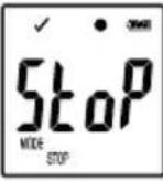 | Start and stop recording by holding button ENTER (7)pressed for few seconds. |
| Mode S | Start mode Stop mode | Remarks | |
| 6 | 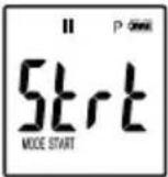 | no display indicator | Start recording by holding button ENTER (7) pressed for few seconds. |
| 7 |  | not applicable | When memory is full, red LED control light (2) is flashing. |
| 8 |  | 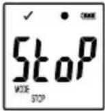 | Stop recording by holding button ENTER (7) pressed for few seconds. |
| 9 | 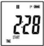 | no display indicator | |
| 10 | 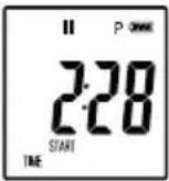 | 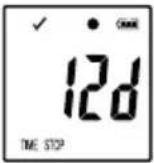 | |
| 11 no display indicator not applicable | |||
| 12 no display indicator | 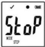 | Stop recording by holding button ENTER (7) pressed for few seconds. | |
| 13 no display indicator | no display indicator | ||
"START DELAY MINUTES"
 | depending on mode 1-13 |
13. Logging data

The data logger is dust tight and jet water protected with attached protective cap (10) and rubber seals (8) only. This protection allows permanent logging operation in damp rooms and outdoors.
Before using ensure that the protective cap is tightly attached to the data logger and the housing is completely closed.
Do not immerse into water!
Avoid operation near strong magnetic fields.
Do not cover the sensor openings.
- Ensure that rubber seals are in the correct positions and that the cap is tightly put on the data logger.
- Place the data logger at the intended location.
- The protective cap must be removed for inserting/changing battery or reading the saved data via a computer. Pull the protective cap off the device.
- Attach the protective cap tightly to data logger before next recording.
a) Enter function menu
Press button DOWN (5) to enter the function menu. The latest recorded measurement, logger ID and selected start/stop mode during configuration appear in sequence by consecutive presses of the button DOWN (5).
b) Start recording
- Recording starts based on configuration setting "RECORD START CONDITION".
- When the data logger starts recording, “●” appears on the LC display.
- “P” indicates data logger is ready for recording and it disappears once the data logger records.
c) Stop recording
- Recording stops based on the configuration setting "STOP STYLE". When the "NONE" stop style was selected, then the recording stops based on the setting "RECORD START CONDITION".
- When the data logger stops recording, “■” appears on the LC display.
d) Show remaining time until start/end of recording
- Press button DOWN (5) to enter the function menu.
- Press button DOWN (5) consecutive until "TIME START" and/or "TIME STOP" and remaining time (in hours/minutes or days) are shown in LC-display.
- Time duration below 24 hours is in HH:MM format. If the remaining time exceeds 24 hours, it is shown as days "a".
- Once the recording starts/stops, the latest measurement is shown in the display.
- Press button DOWN (5) to return to function menu.
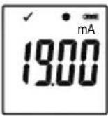
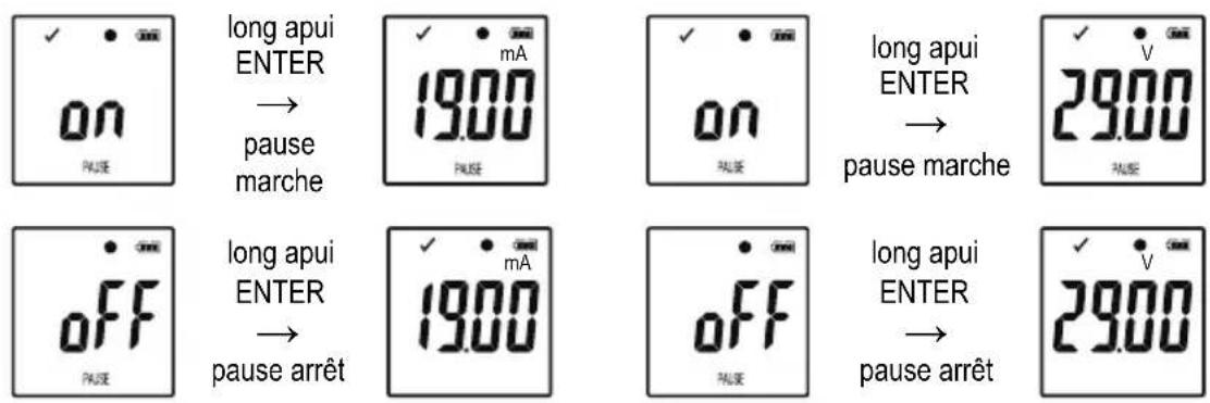
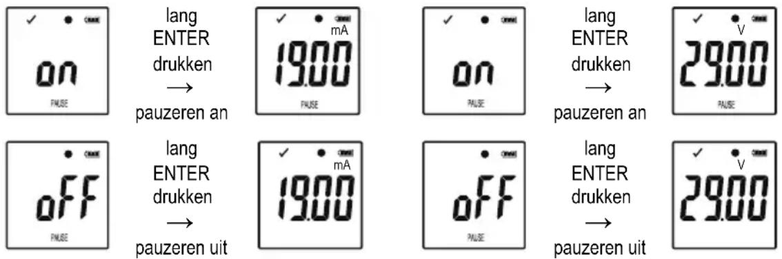
e) Activate/deactivate limit alarm pause function
- In order to activate/deactivate the limit alarm pause function during recording, the limit alarm must be enabled during configuration (please refer to ""MEASUREMENT" options - "ALARM SETTING"" on page 42).
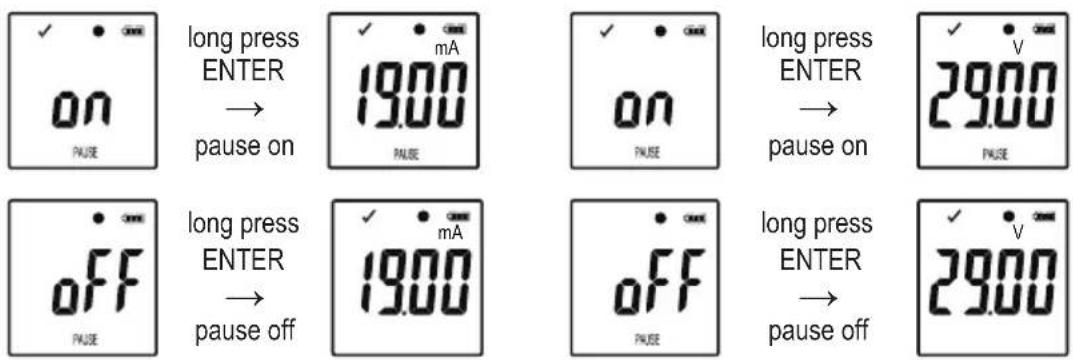
DL-260A: Current (mA) DL-250V: Voltage (V)
text_image
ON pause long press ENTER → pause on 19.00 pause on pause long press ENTER → pause on 29.00 pause OFF pause off 19.00 pause off OFF pause long press ENTER → pause off 29.00- Activate/deactivate limit pause function by holding and pressing button ENTER (7) for few seconds.
- Once the alarm pause function is activated/deactivated, the latest measurement is shown in the display.
→ Recorded values during activated pause function are shown in the report's graph as usual. However, it is clearly indicated in the graph when and for how long the pause function was activated.
When the limit pause function is activated during recording, there will be not any alarm indicator "√" or "X". LED-alarm status, maximum vand Minimum values will not be updated.
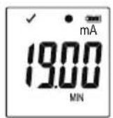
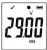
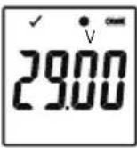
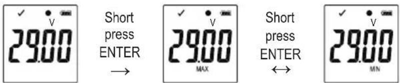
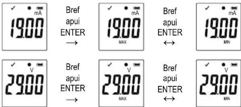
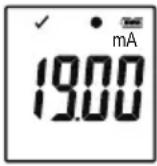
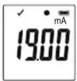
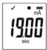
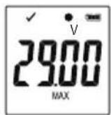
f) Read maximum/minimum measurements
DL-260A: Current (mA)
text_image
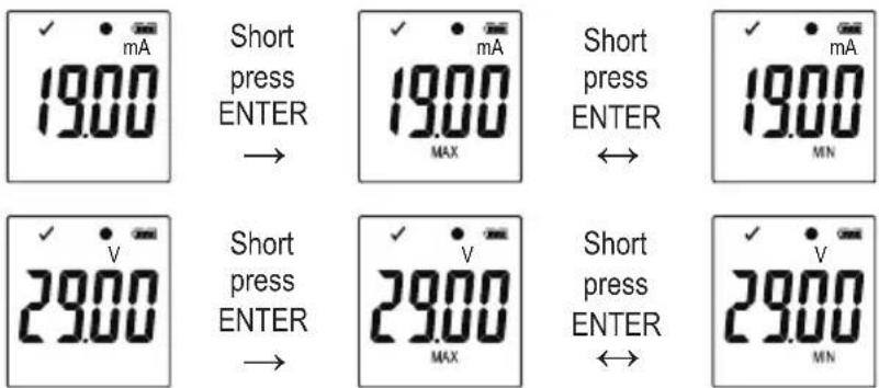
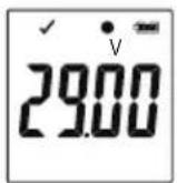
✓ mA 19.00 Short press ENTER → ✓ mA 19.00 MAX Short press ENTER ↔ ✓ mA 19.00 MN ✓ v 29.00 Short press ENTER → ✓ v 29.00 MAX Short press ENTER ↔ ✓ v 29.00 MNDL-250V: Voltage (V)
text_image
✓ v 29.00 Short press ENTER → ✓ v 29.00 MAX Short press ENTER ↔ ✓ v 29.00 MN- Press button DOWN (5) in the function menu several times until you reach the record from which you wish to read the maximum and minimum readings, e.g. current "mA" (DL-260A) or voltage "V" (DL-250V),
- Press button ENTER (7) to enter maximum and minimum reading mode.
- Press button ENTER (7) to switch between maximum and minimum reading in that selected record.
- Press button DOWN (5) to leave the maximum and minimum reading mode.
→ "MAX" indicates maximum and "MIN" indicates minimum value.
Maximum and minimum measurements are recorded from the moment recording starts.
For latest readings, the data logger will sense and update the value on display, unless the limit pause function has been activated. Maximum and minimum readings will stop updating once the device stops logging.
14. Create PDF Report
- Connect the data logger to your computer.
- A PDF report is produced automatically. Red LED control light (2) is on and "USB PDF" is shown in the LC display. Do not disconnect the data logger from your computer during this period.
- Open the data logger drive on your computer.
- Once the PDF file has been generated successfully, "PDF" disappears from the LC display (4). "USB" remains on the LC display.
- Select and open the PDF file.
- The PDF report contains general device information, data logger settings, alarm statuses and a graph showing the measured values during the recorded time.
- Save the PDF file on your computer and close the file.
- Disconnect the data logger from your computer.
→ Depending on the number of stored measurements, generating the PDF file may take up to approximately 30 seconds.
Only the maximum and minimum measurements during recording will be shown in the PDF report but not during the pause function.
15. Delete data
→ Generate and save the PDF report before deleting measured data, if needed.
Deleting data does not affect the configuration settings.
- Press and hold buttons DOWN (5) and ENTER (7) and connect the data logger to your computer. "USB" is shown in the LC display. All data is deleted.
- Release the buttons.
- The data logger driver on your computer is empty, that means all data was successfully deleted. Disconnect data logger from your computer.
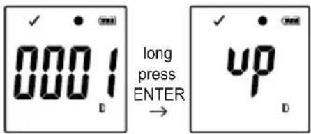
16. Upgrade firmware
- Download the latest data logger firmware from the product page on www.conrad.com.
text_image
0001 long press ENTER → up DPress the button DOWN (5) several times until the 4 digit logger identifier and "ID" are shown on the display. Press and hold the button ENTER (7) until the 4 digit logger ID is replaced by "up".
- Connect the data logger to your computer.
- Drag and drop the firmware to the data logger drive on your computer.
- Data logger starts upgrading. During this period the data logger shown as a mass storage device disappears for a short while from your computer. Do not disconnect data logger from your computer!
- Once the data logger appears as a mass storage device again, the upgrade is finished. Green LED control light flashes twice.
- Disconnect from your computer.
The firmware version of the data logger can be checked in the left bottom corner of the PDF report.
17. Reset to default firmware
→ Resetting the firmware deletes all configuration settings, but does not affect the stored measurement records.
- Remove the battery as mentioned in chapter "9. Initial operation" on page 37.
- Press and hold the button DOWN (5) and connect the data logger to your computer. Once the green LED control light (3) is on, release the button DOWN (5).
- Wait for few minutes until the computer recognizes the data logger as a USB device. The firmware is reset.
- Configure the data logger as mentioned in "11. Configuration" on page 39.
18. Troubleshooting
| Problem Possible solution | |
| The computer does not recognize the data logger. | Check whether “USB” is shown on the data logger after plug in. If so, plug into an another USB port. |
| Check whether the usage of USB mass storage device function on your computer is enabled. | |
| No PDF file is generated. | Check whether data logger has been recognized by your computer. |
| Check whether your computer is displaying the data logger as a new mass storage device. | |
| Check whether data logger is upgrading the firmware (please refer to "16. Upgrade firmware" on page 52). | |
| Unrealistic information on the LC display. | Reset the data logger to firmware (please refer to "17. Reset to default firmware" on page 52). |
| Button ENTER /DOWN does not response although pressed. | |
| LC display is off. | Check whether the LC display is disabled during configuration (please refer to "Other settings" on page 43). |
| Replace the battery. | |
| No LED alarm. | Check whether the LED alarm is disabled in the configuration file (please refer to "Other settings" on page 43). |
| Check whether the alarm has been paused (please refer to "e) Activate/deactivate limit alarm pause function" on page 50). |
Open CSV file
- You can use Excel software to open CSV files. If there is a display error, please refer to the following computer control panel Settings:
- PC setting Control Panel → Region → Additional settings...(Formats Page) → On the Number page, check the list separator.
- The different separator in csv file is applied to different language PC systems.
| PDF File Language settings CSV file list separator | ||
| German ; the semicolon | ||
| English , the comma | ||
| French ; the semicolon | ||
| Italian ; the semicolon | ||
| Dutch ; the semicolon | ||
The separator is default normally. But user can select the suitable separator in computer setting based on operated PC system
19. Maintenance and cleaning
- Besides occasional cleaning, the device is maintenance-free.
- Before cleaning, disconnect the device from the computer.
- Never submerge the product in water.
- Do not use any aggressive cleaning agents, rubbing alcohol or other chemical solutions. Use a dry, soft and clean antistatic cloth to clean the product exterior.
20. Disposal
a) Product
Electronic devices are recyclable waste and must not be disposed of in the household waste. At the end of its service life, dispose of the product according to the relevant statutory regulations. Remove any inserted (rechargeable) batteries and dispose of them separately from the product.
b) Batteries
You as the end user are required by law (Battery Ordinance) to return all used batteries. Disposing of them in the household waste is prohibited.
Contaminated batteries are labelled with this symbol to indicate that disposal in the domestic waste is forbidden. The designations for the heavy metals involved are: Cd = Cadmium, Hg = Mercury, Pb = Lead (name on batteries, e.g. below the trash icon on the left).
Used batteries can be returned to collection points in your municipality, our stores or wherever batteries are sold.
You thus fulfill your statutory obligations and contribute to the protection of the environment.
21. Technical data
Power supply....1 x 3 V button cell, type CR2450
Battery life....1 year (for sampling rate 1 time/min)
Connector type ......USB 2.0
Sampling rate 10 seconds - 24 hours
Measured value....Item No. 2203098 / DL-260A: Current (mA)
Item No. 2203101 / DL-250V: Voltage (V)
Range....Item No. 2203098 / DL-260A: 0.00 - 20.00 mA
Item No. 2203101 / DL-250V: 0.00 - 30.00 V
Memory capacity 31320
Resolution....0.01
Accuracy....±0.5 % (full scale)
System requirements....Windows® XP (with SP1, SP2, SP3) (32 bit), Vista (32/64 bit), 7 (32/64 bit), 8 (32/64 bit), 10 (32/64 bit)
Operating conditions....0 to 50 °C, <80 % RH (non-condensing)
Storage conditions....-10 to +60 °C, <70 % RH (non-condensing)
Dimensions (W x H x D) ....approx. 37 x 86 x 19 mm
Weight 59 g
Page
France (email): technique@conrad-france.fr
| DL-260A: Courant (mA) DL-250V: Tension (V) | |
 |  |
DL-260A: Courant (mA) DL-250V: Tension (V)
DL-260A: Courant (mA)
DL-250V: Tension (V)
text_image
Diagram showing four steps of a device component with numbered labels indicating sequence.11. Configuratie
| DL-260A: Stroom (mA) | DL-250V: Spanning (V) |
 |  |
DL-260A: Stroom (mA) DL-250V: Spanning (V)
DL-260A: Stroom (mA)
DL-250V: Spanning (V)
lang ENTER drukken →
lang ENTER drukken →
lang ENTER drukken ↔
lang ENTER drukken