
VC891 - Measuring equipment VOLTCRAFT - Free user manual and instructions
Find the device manual for free VC891 VOLTCRAFT in PDF.

| Brand | Voltcraft |
| Model | VC891 |
| Product type | Professional digital multimeter |
| Display | Color TFT 60000 counts with bargraph |
| Power supply | 3 AAA micro batteries 1.5 V |
| Dimensions (L x W x H) | 200 x 91 x 43 mm |
| Weight | 430 g (without batteries) |
| Measurement categories | CAT III 1000 V, CAT IV 600 V |
| Main measurements | DC/AC voltage up to 1000 V, DC/AC current up to 10 A, resistance up to 60 MΩ, capacitance up to 60 mF, frequency up to 60 MHz, temperature -40 to +1000 °C, diode and continuity test |
| Special functions | True RMS, LoZ (low impedance), 1 kHz low-pass filter, Bluetooth LE 4.0, data logging, front and rear LED flashlight, COMP function, adjustable auto power off |
| Input protection | High-performance ceramic fuses: 10 A/1000 V and 600 mA/1000 V |
| Basic accuracy | ±0.03% + 5 digits (DC voltage) |
| Communication interface | Bluetooth LE 4.0 (typical range 10 m) |
| Maintenance and cleaning | Clean with a dry, lint-free cloth; calibration recommended once a year; replace batteries and fuses only after disconnecting test leads |
| Safety | Double insulation, pollution degree 2, auto power off, mechanical lock for battery/fuse compartment |
| Supplied accessories | 2 test leads with caps, type K temperature probe (wire -20 to +230 °C), 3 AAA batteries, instruction manual |
| Warranty and repairability | Manufacturer warranty; fuse and battery replacement by user; professional repair recommended |
| Operating temperature | 0 to +40 °C, humidity ≤80% RH |
| Storage temperature | -10 to +60 °C |
| Maximum altitude | 2000 m |
| Number of measurements per second | Approximately 3 readings/s |
Frequently Asked Questions - VC891 VOLTCRAFT
User questions about VC891 VOLTCRAFT
0 question about this device. Answer the ones you know or ask your own.
Ask a new question about this device
Download the instructions for your Measuring equipment in PDF format for free! Find your manual VC891 - VOLTCRAFT and take your electronic device back in hand. On this page are published all the documents necessary for the use of your device. VC891 by VOLTCRAFT.
USER MANUAL VC891 VOLTCRAFT
GB Operating Instructions
Digital multimeter VC891
Page
Item No. 2576866
52 - 97
F Mode d'emploi
7 Symbolerklärung
12 Zusatzfunktionen
2 Introduction....54
3 Intended use....55
4 Product overview ....57
5 Delivery content....59
6 Latest product information....59
7 Explanation of symbols....59
8 Safety information....60
8.1 General information....60
8.2 Handling....61
8.3 Operating environment....61
8.4 Operation....62
9 Product description....63
10 Display elements and symbols....65
11 Taking measurements....67
11.1 Switching the multimeter on and off....68
11.2 Incorrect wiring alarm....68
11.3 DC voltage mode ("V =")....69
11.4 AC voltage mode "V \~" 70
11.5 Measuring AC and DC voltage "V AC+DC"....70
11.6 LoZ voltage mode 71
11.7 Taking current measurements....71
11.8 Measuring frequency/duty cycle in % 73
11.9 Measuring resistance 74
11.10 Diode test....75
11.11 Continuity test ....76
11.12 Measuring capacitance....77
11.13 Temperature measurement....78
12 Additional functions....79
12.1 RANGE function .....79
12.2 MAX/MIN function....79
12.3 REL function .....79
12.4 HOLD function 80
12.5 Automatic shut-off function 80
12.6 COMP function ....80
12.7 RECORD function....80
12.8 SELECT function 81
12.9 SETUP function 81
12.10 Torch function 82
12.11 Bluetooth® mode "BLE" 82
13 Troubleshooting....83
14 Cleaning and care....84
14.1 General information 84
14.2 Cleaning....84
14.3 Opening the battery and fuse compartment 85
14.4 Changing the fuse....86
14.5 Inserting/changing the battery 86
15 Disposal....88
15.1 Product 88
15.2 Batteries/rechargeable batteries....89
16 Declaration of Conformity (DOC)....89
17 Technical data....90
17.1 Power supply 90
17.2 Ambient conditions....90
17.3 Device....90
17.4 Radio module....90
17.5 Measurement tolerances 91
2 Introduction
Dear customer,
Thank you for purchasing this Voltcraft® product.
Voltcraft® produces high-quality measuring, charging and network devices that offer outstanding performance and innovation.
With Voltcraft ^® , you will be able to cope with even the most difficult tasks whether you are an ambitious hobby user or a professional user. Voltcraft ^® offers you reliable technology at an extraordinarily favourable cost-performance ratio.
We are confident that starting to use Voltcraft will also be the beginning of a long, successful relationship.
We hope you enjoy your new Voltcraft® product!
If there are any technical questions, please contact: www.conrad.com/contact
3 Intended use
– Measures and displays electrical parameters in the measurement category CAT III (up to 1000 V) or CAT IV (up to 600 V) against earth potential. Complies with the EN 61010-1 standard and all lower categories.
– Measures direct voltage up to 1000 V
– Measures alternating voltage up to 1000 V
– Measures AC+DC mixed voltage up to 1000 V
– Measures direct and alternating currents up to 10 A
– Measures frequency from 10 Hz to 60 MHz (max. 20 Vrms)
– Displays pulse ratio (duty cycle) in %
– Measures capacitance up to 60 mF
– Measures resistance up to 60 MΩ
- Measuring temperatures from -40 to +1000 °C
- Continuity test (Resistance threshold can be set as 1\~1000 Ω)
- Diode test
- Bluetooth® interface for app control
The measurement modes are selected using the control dial. The measurement range is selected automatically in most modes (except continuity test, diode test and current measurement ranges).
AC voltage frequency 100kHz
AC current frequency 10kHz
Negative polarity readings are indicated with the (-) sign automatically.
A low-impedance mode (LoZ) enables voltage measurement with reduced internal resistance. This suppresses phantom voltages, which may occur in high-impedance measurements. The low-impedance mode must only be used to measure circuits of up to 1000 V for a maximum of 3 seconds.
The two current measurement inputs are protected against overload with high-performance ceramic fuses. The voltage in the measuring circuit must not exceed 1000 V.
The multimeter is powered by three standard micro batteries (type AAA). Only use batteries of the specified type. Rechargeable batteries have a lower capacity and should not be used.
The device switches off automatically after a preset time if no buttons are pressed. This prevents the battery from draining. The automatic shut-off function can be disabled.
The front and rear of the device feature a switchable LED lamp that can be used as a torch.
There is a fold-out stand on the rear of the device. This allows you to place the multimeter on a level surface for better readability. There is also an integrated tripod socket on the back.
Do not use the multimeter when the battery compartment is open or when the battery compartment cover is missing. A protective mechanism prevents the battery compartment from opening when test leads are connected.
Do not take measurements in potentially explosive areas, damp rooms or adverse conditions. Unfavourable ambient conditions include: Moisture or high humidity, dust and flammable gases, vapours or solvents, thunderstorms and strong electromagnetic fields.
For safety reasons, only use test leads or accessories that match the multimeter's specifications.
The multimeter must only be used by people who are familiar with the relevant regulations and understand the potential hazards. The use of personal protective equipment is recommended.
Using this product for any purposes other than those described above may damage the product and result in a short circuit, fire or electric shock. The product must not be modified or reassembled!
Read the operating instructions carefully and keep them in a safe place for future reference.
Always observe the safety information in these instructions!
Brand names mentioned herein are the property of their respective owners.
4 Product overview
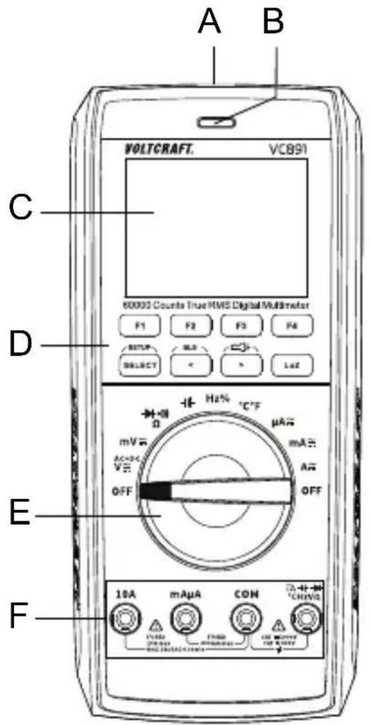
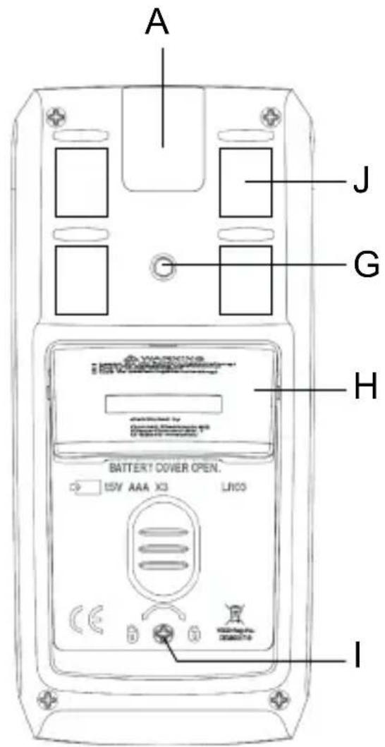
A LED torch
B Optical actuation control
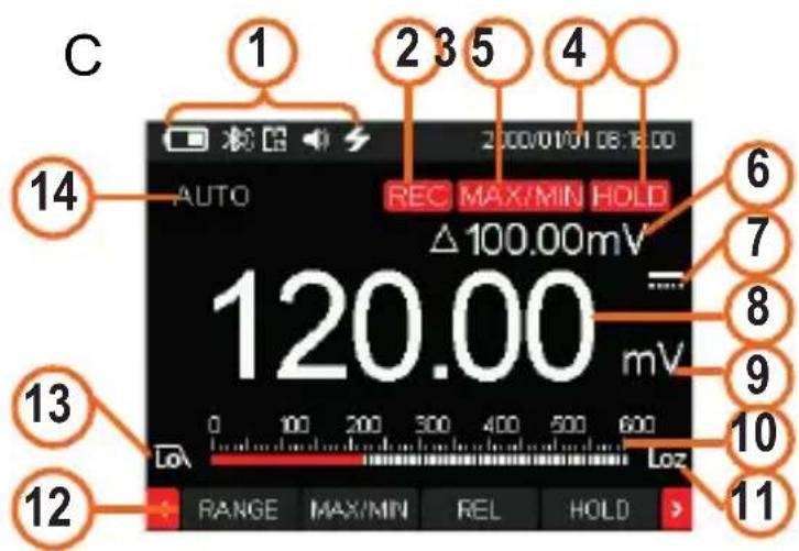
C Colour display, graphics compatible
(1) System symbols (from left to right: battery level, Bluetooth®, APO, sound, torch, lightning for dangerous voltage)
(2) REC display, active
(3) MAX/MIN display, active
(4) System date and time
(5) HOLD display, active
(6) Relative value display
(7) DC/AC current display
(8) Measurement display
(9) Measuring unit display
(10) Bar graph display
(11) LoZ low impedance, active
(12) Functions for buttons F1 to F4
(13) Low-pass filter enabled
(14) MAX/MIN and AUTO range function
D Function buttons
E Control dial for selecting the measurement mode
F Measurement sockets
G Connection thread for stand
H Fold-out stand
I Screw for battery and fuse compartment
J Magnetic measuring tip holder for enclosed measuring tips

Caution, strong magnet! Keep the device away from pacemakers, defibrillators or check cards.
5 Delivery content
Digital multimeter
2x safety test leads with CAT III/CAT IV protective caps
Wire temperature probe, type-K (-20 to +230 °C)
3x micro batteries (AAA)
Operating instructions
6 Latest product information
Download the latest product information at www.conrad.com/downloads or scan the QR code shown. Follow the instructions on the website.

7 Explanation of symbols
The following symbols appear on the product/device or in the text:

This symbol warns of hazards that can lead to injury.
This symbol warns of a dangerous voltage which can lead to injuries due to electric shock.

Protection class 2 (double or reinforced insulation, protective insulation)
CAT I
Measurement Category I: For measuring circuits of electrical and electronic equipment that is not directly supplied with a mains voltage (e.g. battery-operated devices, safety extra-low voltage systems, signal/control voltages, etc.)
| CAT II | Measurement Category II: For measuring circuits of electrical and electronic equipment that is directly supplied with a mains voltage via a mains plug. This category also includes all lower categories (e.g. CAT I for measuring signal and control voltages). |
| CAT III | Measurement Category III: For measuring circuits of installations in buildings (e.g. mains sockets or sub-distributions). This category also includes all lower categories (e.g. CAT II for measuring electrical devices). Measuring in CAT III is only permitted with test prods with a maximum free contact length of 4 mm or with cover caps over the test prods. |
| CAT IV | Measurement Category IV: For measuring at the origin of a low-voltage installation (e.g. mains distribution, electricity provider's transfer points to homes) and outdoors (e.g. when conducting tasks on underground cables or overhead lines). This category also includes all lower categories. Measuring in CAT IV is only permitted with test prods with a maximum free contact length of 4 mm or with cover caps over the test prods. |

Earth potential
8 Safety information

Read the operating instructions carefully and especially observe the safety information. If you do not follow the safety instructions and information on proper handling, we assume no liability for any resulting personal injury or damage to property. Such cases will invalidate the warranty/guarantee.
8.1 General information
This product is not a toy. Keep it out of the reach of children and pets.
Do not leave packaging material lying around carelessly. It may become a dangerous plaything for children.
Should you have any questions or concerns after reading this document, please contact our technical support or a professional technician.
Maintenance, adjustment and repair work may be carried out only by an expert or a specialist workshop.
8.2 Handling
Please handle the product carefully. Impact, shocks or a fall even from a low height can damage the product.
To prevent an electric shock, do not touch the measuring points when taking measurements, either directly or indirectly. When taking measurements, do not touch any area beyond the grip markings on the probe tips.
8.3 Operating environment
Do not expose the product to any mechanical stress.
Protect the product from extreme temperatures, strong jolts, flammable gases, vapours, and solvents.
Protect the product from high humidity and moisture.
The product must not be exposed to direct sunlight.
Never switch the product on immediately after taking it from a cold into a warm environment. This may cause condensation to form, which can destroy the product. Allow the product to reach room temperature before using it.
Do not use the device shortly before or after a thunderstorm (lightning! /high-power surges!). Ensure that your hands, shoes, clothes, the floor, circuit and circuit components are dry.
Avoid operation near strong magnetic or electromagnetic fields, transmitter aerials or HF generators. Otherwise, the product may not function properly.
8.4 Operation
Consult an expert when in doubt about the operation, safety or connection of the device.
For installations in industrial facilities, follow the accident prevention regulations for electrical systems and equipment issued by the national safety organisation or the corresponding national authority.
In schools, educational facilities, and hobby and DIY workshops, meters must be used under the responsible supervision of qualified personnel. The same applies when the meter is used by people with reduced physical and mental capabilities.
Always ensure that the multimeter is set to the correct measurement mode before taking a measurement.
Always remove the test probes from the measured object before changing the measurement range.
Check the multimeter and test leads for signs of damage before each measurement. Never take measurements if the protective insulation is damaged (torn, missing, etc.). The test leads come with a wear indicator. The second layer of insulation will become visible if the lead is damaged (the second layer of insulation is a different colour). If this occurs, discontinue use and replace the measurement accessory.
The voltage between the multimeter connection points and the earth must not exceed 1000 V DC/AC in CAT III or 600 V DC/AC in CAT IV.
Exercise particular caution when working with voltages higher than 33 V (AC) and 70 V (DC)! Touching electrical conductors with these voltages may cause a fatal electric shock.
When using test probes without protective caps, measurements between the multimeter and the earth potential must not exceed the CAT II measurement category.
When taking CAT III measurements, the protective caps must be placed on the probe tips (max. length of exposed contacts = 4 mm) to avoid accidental short
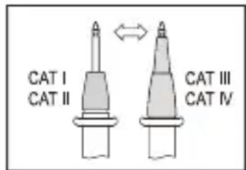
circuits. These are supplied with the device and pre-mounted on the test probes.
If it is no longer possible to operate the product safely, stop using it and prevent unauthorised use. DO NOT attempt to repair the product yourself. Safe operation can no longer be guaranteed if the product:
– is visibly damaged,
– is no longer working properly,
– has been stored for extended periods in poor ambient conditions or
– has been subjected to any serious transport-related stress.
9 Product description
The digital multimeter (multimeter) displays measurements on a digital display (display). The multimeter features a digital 60000-count display (count = smallest display value). The multimeter monitors the correct socket assignment. The multimeter beeps and displays a warning when the sockets are not assigned correctly. This increases the operational safety of the multimeter for the user.
The multimeter switches off automatically after a preset time if no buttons are pressed. This protects the batteries and extends the battery life. The automatic shut-off feature can be preset and disabled manually.
The multimeter can be used to take measurements up to CAT III 1000 V/CAT IV 600 V. It is suitable for use in hobby and professional applications.
The multimeter can be placed on a level surface using the fold-out stand for better readability.
The battery and fuse compartment can only be opened when all test leads have been disconnected from the multimeter. When the battery and fuse compartment are open, the test leads cannot be inserted into the measurement sockets. This is a built-in safety feature to protect the user.
A switchable Bluetooth® interface enables device operation using a smartphone/tablet with Bluetooth® LE 4.0 interface. The free measurement app compatible with Android or iOS devices can be found on the public download portals. The app also allows recording your measurements.
It is available for Android devices from version 6.0 or later and iOS devices from version 11.0 or later (iPhone 5 or later).
Control dial (E)
Individual measurement modes are selected using the control dial. Automatic range selection (“Autorange”) is enabled in most measurement modes. The measurement range will be selected automatically. The current measurement ranges must be set manually. Always start current measurements with the largest measurement range, and then switch to a smaller range if necessary.
The control dial features an indicator light that shows the setting position. Use the “SELECT” button to switch to a sub-mode when the measurement mode has more than one function (e.g. to switch from resistance measurement to diode test or continuity test or from AC to DC current). The function is toggled with each press.
To switch the multimeter off, move the control dial to the "OFF" position. Always turn the multimeter off when it is not in use.
10 Display elements and symbols
The following symbols and letters appear on the device/display. Other symbols may appear on the display (display test), but these have no function.
True RMS True effective measurement
Δ Delta symbol for relative measurement (= reference measurement).
M Mega symbol (exp. 6)
k Kilo symbol (exp. 3)
Ω Ohm (unit of electrical resistance)
Hz Hertz (unit of frequency)
n Nano symbol (exp. -9)
μ Micro symbol (exp. -6)
m Milli symbol (exp. -3)
V Volt (unit of electrical voltage)
A Ampere (unit of electrical current)
F Farad (unit of electrical capacity)
°C/°F Degrees Celsius / Degrees Fahrenheit (unit of temperature)
REL Relative measurement button (= reference measurement)
SELECT Switches to sub-mode
SETUP Setup menu
BLE Enable Bluetooth® interface
HOLD Freezes the current measurement
OL Overload; the measurement range was exceeded
Check inPut Warning message "Wrong measurement socket selection".
OFF Move to this position to turn the multimeter off
Diode test symbol
Acoustic continuity tester symbol
- Capacity measuring range symbol
\~ Alternating current symbol

Direct current symbol
COM Connection for reference potential

Torch symbol

Bluetooth
® interface symbol
</> Arrow buttons to navigate through the function menu
MAX/MIN Hold the maximum or minimum measurement
COMP Value comparison; compare the current measurement with the set maximum and minimum measurements for a quick assessment.
RECORD Automatic recording of measurements. Measurements are sent to the measurement app using a mobile device. A flashing dot on the “REC” display indicates the storage process
RECORD STOP Stop recording measurements
SAVE Manual saving of measurements
LOG Read out manually stored measurements
PEAK Peak value display (only in AC mode)
Lo 1 kHz low-pass filter suppresses high-frequency interference signals (only in ACV mode)
FREQ Frequency display (only in AC mode)
11 Taking measurements

Never exceed the maximum permitted input values. Never touch circuits or parts of circuits when they may contain voltages greater than 33 V/ACrms or 70 V/DC! Danger to life!
Measurements can only be taken when the battery and fuse compartment is closed. Cables cannot be inserted when the compartment is open.
Before measuring, check the connected test leads for damage, such as cuts, tears and kinks. Never use defective test leads! Danger to life!
When taking measurements, do not touch any area beyond the grip markings on the probe tips.
Only connect the two test leads that you require to take measurements. For safety reasons, remove all unnecessary test leads from the multimeter before taking a measurement.
Measurements in electrical circuits rated at >33 V/AC and >70 V/DC must only be carried out by qualified and trained personnel who are familiar with the relevant regulations and the associated hazards.
Check the multimeter for functionality before each measurement. An incorrect check result indicates a possible malfunction. The multimeter must be checked.
“OL” (overload) indicates that the measurement range has been exceeded.
11.1 Switching the multimeter on and off
Turn the control dial (E) to select the desired mode.
The optimal measurement range is automatically selected (except in current mode). When measuring a current, always start with the largest measurement range, and then switch to a smaller range if necessary. Always disconnect the test leads from the measured object before switching to another mode.
To turn the multimeter off, move the control dial to the "OFF" position. Always turn the measurement device off when it is not in use.
Before storing the multimeter, insert the test leads into the high-impedance measurement sockets (COM and V). This helps to prevent errors when making subsequent measurements.

The included test lead plugs are fitted with transport protection caps. These caps must be removed before inserting the test leads into the measurement sockets.
Before using the multimeter, you must insert the included batteries. For more information on inserting/replacing the batteries, see "Cleaning and care".
11.2 Incorrect wiring alarm
The multimeter automatically detects which sockets are connected to the test leads. If the test leads are connected to the wrong sockets (which can be dangerous for the user and damage the multimeter), the multimeter triggers an acoustic and optical alarm.
If you switch to another measurement mode (except current mode) when the test leads are connected to the sockets, the multimeter triggers an alarm. The alarm is also triggered when the measuring input is switched from the 10 A socket to the mAμA one.
If the alarm is triggered and “Check InPut” (followed by the relevant socket) appears on the display, check that the leads are connected to the correct sockets and that you have selected the correct measurement mode.

If the alarm is triggered, check that you have selected the correct measurement mode and that the cables are connected to the correct sockets.
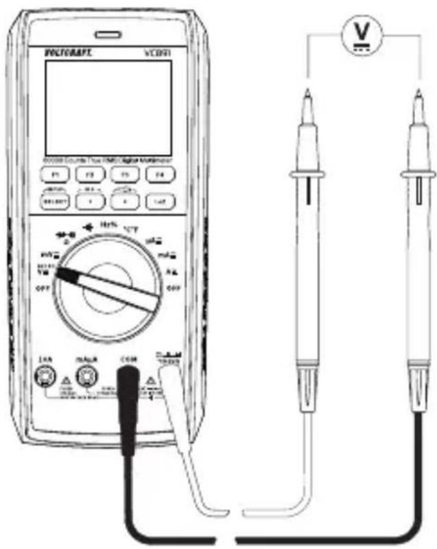
11.3 DC voltage mode ("V=")
Proceed as follows to measure DC voltages:
Turn the multimeter on and select "V-mode." "and-V" will appear on the display. For lower voltages up to max. 600 mV, select the "mV" measurement function.
Plug the red test lead into the V measurement socket and the black test lead into the COM measurement socket.
Connect the two test probes in parallel to the object that you want to measure (e.g. battery or circuit). Connect the red test probe to the positive terminal and the black test probe to the negative terminal.
The measured value and polarity are indicated on display.
If “-” appears in front of a direct voltage measurement, this indicates that the measured voltage is negative (or that the test leads have been connected in reverse).
The “V DC” voltage range has an input resistance of ≥10 M ; the “mV DC” range has an input resistance of ≥5 M .
After taking a measurement, remove the test leads from the measured object and turn the multimeter off.
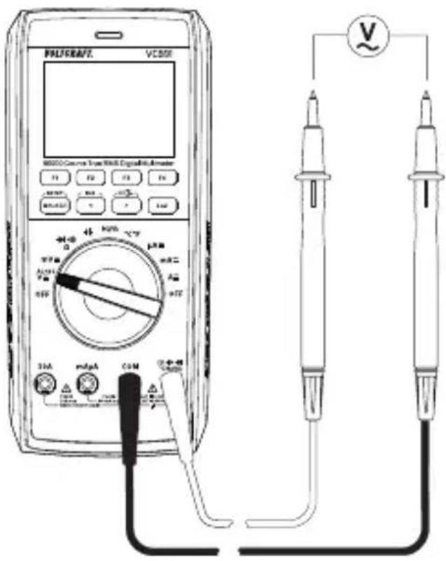
11.4 AC voltage mode "V\~
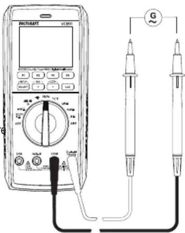
Proceed as follows to measure AC voltages:
Turn the multimeter on and select "V" mode. Press the "SELECT" button to switch to "AC" mode. "and "V" will appear on the display.
For lower voltages up to max. 600 mV, select the "mV" measurement range.
Plug the red test lead into the V measurement socket and the black test lead into the COM measurement socket.
Connect the two test probes in parallel to the object that you want to measure (e.g. generator or circuit).
The measured value appears on display.
After measuring, remove the test leads from the measured object and turn the multimeter off.
The “V/AC” voltage range has an input resistance of ≥10 M . This means that there is almost no load on the circuit.
11.5 Measuring AC and DC voltage "V AC+DC"
You can measure mixed voltages as follows:
Turn the multimeter on and select "V AC+DC" mode. Press the "SELECT" button twice to switch to AC+DC mode. "and "V" will appear on the display.
Perform the connection and measurement as described under "Measuring AC voltage". The display shows the complete mixed voltage (AC+DC).
11.6 LoZ voltage mode
LoZ mode allows you to measure DC and AC voltages with a low impedance (approx. 400 kΩ). In this mode, the multimeter lowers the internal resistance to prevent “phantom” voltage readings. As a result, the circuit is more heavily loaded than in the standard measurement mode.
To enable LoZ mode, press the "LoZ" button when taking a voltage measurement. The impedance will be reduced until you release the button. In the LoZ mode, a beep sounds and the display (B) is indicated.
The “Loz” symbol (C9) appears on the display.

The LoZ mode can only be used for circuits with a voltage of up to 1000 V. The duration of the LoZ measurement must be limited to a maximum of 3 s.
After using the LoZ mode, leave the multimeter for 1 minute before using it again.
11.7 Taking current measurements

Never exceed the maximum permitted input values. Never touch circuits or parts of circuits when they may contain voltages greater than 33 V/ACrms or 70 V/DC! Danger to life!
The voltage in the measured circuit must not exceed 1000 V.
Measurements greater than 10 A must only be made for a maximum of 10 seconds in 10-minute intervals.
Always start the current measurement using the largest measurement range, and then switch to a smaller range if necessary. Always disconnect the circuit before connecting the multimeter and changing the measurement range. All current measurement ranges are protected against overload.
Do not measure any currents above 10 A in the A range or currents above 600 mA in the mA/ A range, as this will trigger the fuses.
Current measurements should be made as quickly as possible. Avoid taking measurements for prolonged periods.
An optical and acoustic alarm is triggered when the measurement range is exceeded.
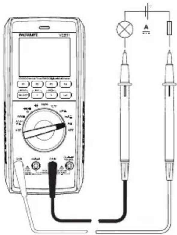
Proceed as follows to measure direct currents (A ---):
Switch the multimeter on and select "10A, mA, or μA" mode.
The table shows the different measurement modes and the corresponding measurement ranges. Select the desired measurement range and corresponding measurement sockets.
| Measurement mode Measurement range Measurement sockets | |
| μA <6000 μA COM + mAμA | |
| mA 6 mA – 600 mA COM + mAμA | |
| 10 A 600 mA – 10 A COM + 10 A | |
Insert the red test lead into the mAμA or 10A measurement socket. Insert the black test lead into the COM measurement socket.
Connect the two test probes in series to the object that you want to measure (e.g. battery or circuit). The electrical circuit must be disconnected before you connect the probes.
■Reconnect the circuit. The measured value appears on display.
■After taking a measurement, disconnect the circuit and remove the test leads from the measured object. Switch the multimeter off.
Proceed as follows to measure alternating currents (A\~):
Switch the multimeter on and select "10A, mA, or μA" mode. Press the "SELECT" button to switch to AC mode. The display shows ".Press the "SELECT" button again to switch back to DC mode.
Connect the multimeter to the corresponding measuring inputs and the measuring circuit as described in "DC measurement" and follow the steps below.
11.8 Measuring frequency/duty cycle in %
The multimeter can be used to measure the frequency of a signal voltage (supports frequencies from 10 Hz to 10 MHz). The maximum input is 20 Vrms. This mode is not suitable for taking measurements on mains voltages. Observe the input specifications in the technical data.
Proceed as follows to take a frequency measurement:
Switch on the multimeter and select "Hz" mode. "Hz" appears on the display.
Plug the red test lead into the Hz measurement socket and the black test lead into the COM measurement socket.
Connect the two test probes to the object that you want to measure (e.g. signal generator or circuit).
The frequency and corresponding unit will be indicated on the main display. The sub-display will show the pulse ratio of the positive half-wave in %. Pressing the "SELECT" button toggles the "Hz/%" display.
After measuring, remove the test leads from the measured object and turn the multimeter off.
11.9 Measuring resistance

Make sure that all objects that you wish to measure (including circuit components, circuits and component parts) are disconnected and discharged.
Follow the steps below to measure the resistance:
Turn on the multimeter and select the “Ω” measurement mode.
Insert the red test lead into the measurement socket, the black test lead into the COM measurement socket.
Check the test leads for continuity by connecting both test probes to one another. The multimeter should then show a resistance value of approx 0–0.5 Ω (inherent resistance of the test leads).
For low-impedance measurements of <600 Ω, press the F3 "REL" button when the measuring probes are short-circuited. This ensures that
the inherent resistance of the test leads does not affect the resistance measurement. The display should show 0 Ω.
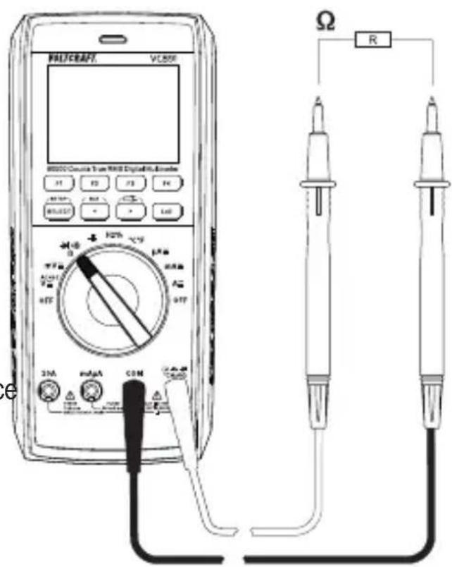
Connect the test probes to the object that you want to measure. The measurement value will be indicated on the display (provided that the object you are measuring is not highly resistive or disconnected). Wait until the display stabilises. This may take a few seconds for resistances greater than 1 MΩ.
“OL” (overload) indicates that the measurement range has been exceeded or that the circuit is broken.
After measuring, remove the test leads from the measured object and turn the multimeter off.
When taking a resistance measurement, make sure that the points that come into contact with the probe tips are free from dirt, oil, solder and other impurities. These substances may distort the result.
The “REL” button only works when a measurement is displayed. It cannot be used when “OL” is displayed.
11.10 Diode test

Make sure that all objects that you wish to measure (including circuit components, circuits and component parts) are disconnected and discharged.
■Turn the multimeter on and select the measurement mode
Press the "SELECT" button twice to switch to diode test mode. The diode symbol and "V" appear on the display. Press the button again to switch to the next measurement mode.
Insert the red test lead into the measurement socket, the black test lead into the COM measurement socket.
Check the measuring leads for continuity by connecting both measuring probes to one another. A value of approx. 0.000 V should be shown.
Connect the two test probes to the object that you want to measure (diode). Connect the red test lead to the anode (+) and the black test lead to the cathode (-).
The continuity voltage ("UF") will be shown in Volts (V). "OL" indicates that the diode is reverse-biased (UR) or defective (interrupted). Try taking the measurement again with the opposite polarity.
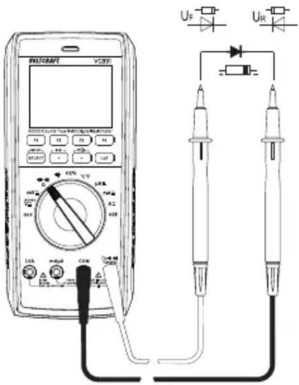
After measuring, remove the test leads from the measured object and turn the multimeter off.
11.11 Continuity test

Make sure that all objects that you wish to measure (including circuit components, circuits and component parts) are disconnected and discharged.
■Turn the multimeter on and select measurement mode ••••).
Press the "SELECT" button once to switch to continuity test mode. The continuity test symbol and the symbol appear on the display. Press the key again to switch to the next measuring mode.
Insert the red test lead into the measurement socket, the black test lead into the COM measurement socket.
Resistance threshold can be set as 1\~1000 Ω. The continuity test measures resistances of up to 1000 Ω.
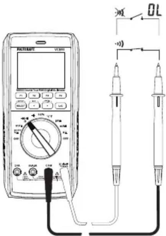
“OL” (overload) indicates that the measuring range has been exceeded or that the circuit is broken.
After measuring, remove the test leads from the measured object and turn the multimeter off.
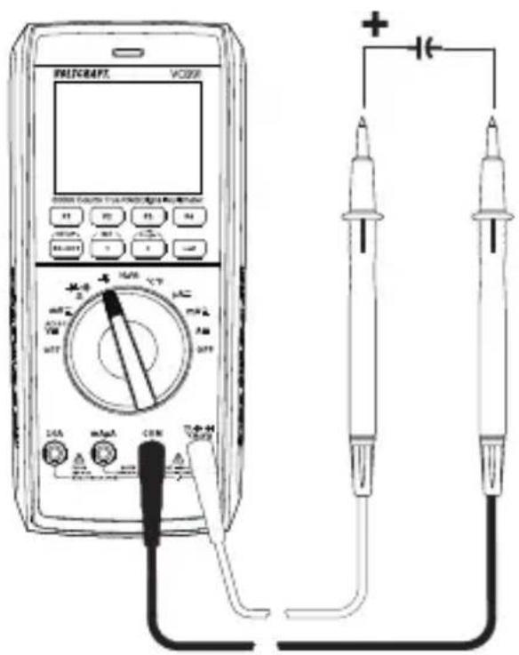
11.12 Measuring capacitance

Make sure that all objects that you wish to measure (including circuit components, circuits and component parts) are disconnected and discharged.
Always pay attention to the polarity when using electrolytic capacitors.
■Turn the multimeter on and select the measurement range
Plug the red test lead into the V measurement socket and the black test lead into the COM measurement socket.
The display shows "nF".
Connect the two test probes (red = positive, black = negative) to the object that you want to measure (capacitor). The capacitance will be shown on the display after a few seconds. Wait until the display stabilises. This may take a few seconds for capacitances greater than 60 F.
“OL” (overload) indicates that the measuring range has been exceeded.
After measuring, remove the test leads from the measured object and turn the multimeter off.
Due to the sensitive measuring input, the display may show a value if the test leads are “open”. Press the “REL” button to measure small capacities (<600 nF). The display then shows “0”. The Autorange function is thus deactivated.
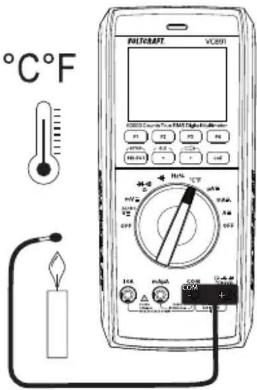
11.13 Temperature measurement

During temperature measurement, only the temperature probe may be exposed to the temperature to be measured. The working temperature of the measuring instrument must not be exceeded or fallen short of, otherwise measurement errors may occur.
The contact temperature probe may only be used on stress-free surfaces.
All K-type thermocouples can be used for temperature measurement. The temperatures can be displayed in °C or °F. The enclosed wire probe is suitable for the range -20 to +230°C. With optional probes, the entire measurement range (-40 to +1000 °C) can be used.
Switch on the DMM and select the measuring function “°C°F”.
Plug the enclosed wire thermocouple into the °C (+) and COM (-) measurement sockets with correct polarity.
The temperature value with the corresponding unit appears in the display.
Switching from °C to °F is done via the „SELECT“ key.
As soon as „OL“ (for overload) appears in the display, you have exceeded the measuring range.
If no probe is connected, the device temperature is displayed via the internal probe.
Remove the probe from the measuring object after the end of the measurement and switch off the DMM.
12 Additional functions
You can use the function buttons (F1 to F4) to enable a range of different functions. The multimeter beeps each time you press a button. Some additional functions are not available in some measurement modes. The unavailable functions are highlighted in dark grey and cannot be activated.
12.1 RANGE function
The RANGE button serves for the manual setting of a defined measurement range. The Autorange function is deactivated. Each time you press the button, the measurement range display toggles. Press and hold the button for approx. 1 second to activate the AUTO function again. A beep will sound and “AUTO” appears on the display.
12.2 MAX/MIN function
The MAX/MIN function enables you to store the measurements for a short time. Each selected range (MAX or MIN) is recorded and displayed. The function is toggled with each press. Press and hold the button for approx. 1 second to activate the MAX/MIN function again. A beep will sound and "AUTO" appears on the display.
12.3 REL function
The REL function allows you to take a reference measurement to avoid possible line losses (e.g. during resistance measurements). For this purpose, the current indicated value is set to zero. A new reference value is set.
Press the “REL” button to enable this function. The display shows “ ” and the measurement will be reset to zero. The automatic measurement range selection function will be disabled.
To disable this function, change the measurement mode or press and hold the button for approx. 1 second.

The REL function is not available in the “continuity test” mode.
The “REL” button only works when a measurement is displayed. It cannot be used when “OL” is displayed.
12.4 HOLD function
This function freezes the current reading on the display so that you can record it for future reference.

When testing live wires, ensure that this function is disabled before taking any measurements. Otherwise, a false measuring result is simulated!
Press the "HOLD" button to enable this feature. The multimeter will beep and "HOLD" will be displayed.
To disable the hold feature, press the "HOLD" button again or change the measurement mode.
12.5 Automatic shut-off function
The multimeter switches off automatically after a preset time if no buttons are pressed or the control dial is not used. This function saves battery power and extends the battery life. The time symbol will be displayed at the top left when the automatic shut-off feature is enabled.
The multimeter will beep one time approx. 1 minute before it turns off. You will hear a long beep when the multimeter switches off. Pressing any button or moving the control dial interrupts the shut-off sequence.
To switch the multimeter back on, move the control dial over the "OFF" position or press the "SELECT" button.
The automatic shut-off feature can be adjusted using the setup function and disabled manually.
12.6 COMP function
The COMP function allows automatic comparison of measurements with preset limits. Hence, it allows quick evaluation of measurements during time-intensive measurement series.
12.7 RECORD function
The RECORD function allows mobile recording of measurements via the Bluetooth® interface on the measurement app installed on your smartphone or tablet.
12.8 SELECT function
Some measurement modes have additional sub-modes. The sub-modes are marked in grey around the control dial. To switch to a sub-mode, press the “SELECT” button. Press the button again to switch to the next sub-mode.
12.9 SETUP function
The setup menu serves to configure various system parameters according to your needs. To select the setup menu, press the "SETUP" button. Use the function buttons "F1" and "F2" to navigate through the menu and select menu items.
Use the two arrow buttons "<" and "> " to select the fields you wish to set.
Use the function buttons "F3" and "F4" to change values. Press the "SETUP" button again to exit the setup menu.
Brightness Display backlight
Sound Button tones
Color Mode Display theme (light/dark)
Auto Power Off Automatic shut-off (Always ON = disabled)
Display Display backlight switch-off time
Key Light Position illumination on the control dial
Torch Time Torch switch-off time (Always ON = disabled).
Cont Threshold Acoustic continuity test threshold (1 - 1000 Ω)
Set Time System time setting (hours:minutes:seconds)
Set Date Date setting
Date Format Date Format (DD = day, MM = month, YY = year)
Compare Type Comparison type (INNER = within tolerance, OUTER = outside tolerance)
Compare Min Lower tolerance limit
Compare Max Upper tolerance limit
Record Num Number of stored values (1 - 10000 values)
Record Rate Storage interval (1 - 10000 s)
Factory Reset Restore factory settings
Device Info System information display
12.10 Torch function
The multimeter features two integrated white LED lamps. These LED lamps serve as torches.
Pressing the button with the torch symbol activates the torch function. The function buttons "F1" to "F4" can also be used to activate this function.
F1 TORCH activates the torch function
F2 FRONT activates the LED lamp on the front side
F3 BACK activates the LED lamp on the rear side
F4 EXIT exits the torch menu
12.11 Bluetooth® mode "BLE"
The integrated Bluetooth® interface allows transferring measurement data from the meter to a smartphone or tablet for their subsequent limited control.
This mode is compatible with smartphones or tablets with a Bluetooth® LE 4.0 interface. The app “Voltcraft VC800-Series” is available free of charge at “Google Play” or in the “App Store” from Apple and must be installed before you can use it.
Install the app on your smartphone or tablet.
Activate the Bluetooth® mode on your smartphone or tablet.
Activate the Bluetooth® mode on the meter. To do this, press and hold the button "BLE" for approx. 2 seconds. When the interface is enabled, you will hear a confirmation beep and the Bluetooth® symbol will be displayed on the left in the top line.
Open the app on your smartphone or tablet and create a new project by tapping on the large “plus sign” in the middle of the screen. Select your meter “VC891” from the list of available devices. A chain symbol displayed next to the interface symbol indicates that the meter is connected with the app. Measurement data can now be transferred. Measurement data are transferred from the meter to the app for their subsequent limited control. The knob function cannot be controlled!
For operation and configuration in the app, please refer to the separate app operating instructions.
This is available under the listed URL in the chapter „Latest product information“.
13 Troubleshooting
| Error Possible cause Solution | ||
| The multimeter does not work. | Are the batteries empty? | Check the status. Replace the batteries. |
| The measured value does not change. | Have you selected the wrong measurement mode (AC/DC)? | Check the display (AC/DC) and select another mode if necessary. |
| Did you use the wrong measurement sockets? | Check that the test leads are connected to the correct measurement sockets. | |
| Is the hold function enabled? | Disable the hold function. | |
| The multimeter cannot take measurements in the 10 A range | Is the fuse in the 10 A input defective? | Check the 10 A fuse. |
| The multimeter cannot take measurements in the mA/μA range | Is the fuse in the mAμA range defective? | Check the 600 mA fuse. |
| No Bluetooth® connection to smartphone | Is the Bluetooth® mode enabled on both devices? | Check that the Bluetooth® mode is enabled on the multimeter and the smartphone/tablet |
14 Cleaning and care
Important:
- Do not use aggressive cleaning agents, rubbing alcohol or other chemical solutions. They can damage the housing and can cause the product to malfunction.
- Do not immerse the product in water.
14.1 General information
The multimeter should be calibrated once a year to ensure that measurements remain accurate.
The multimeter does not need to be serviced (apart from occasional cleaning and replacing the battery/fuse).
Refer to the following sections for instructions on how to change the fuse and battery.

Regularly check the device and measuring leads for signs of damage.
14.2 Cleaning
Always observe the following safety information before cleaning the device:

Opening any covers on the product or removing parts – unless this is possible by hand – may expose voltage-carrying components.
Before cleaning or servicing the multimeter, disconnect all cables from the multimeter and all measured objects. Power the multimeter off.
Do not use abrasive detergents, petrol, alcohol or other similar chemicals to clean the device. They may damage the surface of the device. In addition, the vapours emitted by these substances are explosive and harmful to your health. Do not use sharp-edged tools, screwdrivers or metal brushes to clean the device.
Use a clean, damp, lint-free and antistatic cloth to clean the device, display and test leads. Allow the device to dry completely before using it again.
14.3 Opening the battery and fuse compartment
For safety reasons, fuses and batteries may only be replaced after all test leads were removed from the multimeter. You cannot open the battery and fuse compartment (I) when the test leads are connected to the sockets.
In addition, the measurement sockets are automatically locked when the battery and fuse compartment is opened to prevent leads from being inserted. The sockets are unlocked when the battery and fuse compartment is closed.
The multimeter casing is designed so that you can only access the battery and fuse compartment. The casing does not need to be opened and disassembled.
This makes the multimeter safer and easier to use.
Follow the steps below to open the battery and fuse compartment:
- Disconnect all test leads from the multimeter and switch it off.
Unfold the fold-out stand on the back of the multimeter.
Loosen and remove the battery compartment screw (I) on the back of the multimeter.
Remove the cover of the battery and fuse compartment (P) by sliding it upwards and then lifting it off the device. You should first disconnect all test leads from the multimeter to be able to remove the cover.
You should now be able to access the fuses and the battery compartment.
Repeat the above steps in the reverse order to replace the battery and fuse compartment, and then screw it in place.
The multimeter is now ready for use.
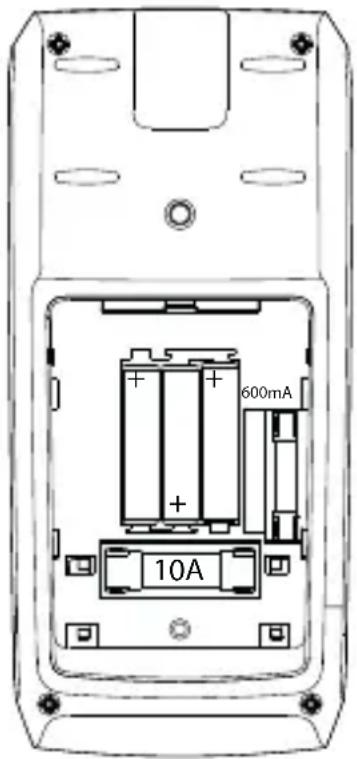
14.4 Changing the fuse
The two current measuring inputs are equipped with high-performance ceramic fuses. If you cannot take measurements in this range, you will need to replace the fuse.
Proceed as follows to replace the fuse:
- Disconnect the test leads from the measurement circuit and the multimeter. Power the multimeter off.
Remove the battery and fuse compartment cover (see “Opening the battery and fuse compartment” for details). - Replace the defective fuse with a new one of the same type and nominal voltage. The fuses have the following specifications:
Ceramic Superflink 10 A/1000 V, 10 kA disconnecting capacity
Dimensions: 37 mm x 10 mm
Ceramic Superflink 600 mA/1000 V, 6FA
Dimensions: 32 mm x 6.4 mm
Carefully replace the battery and fuse compartment cover.

Using patched fuses or bridging the fuse holder is not permitted for safety reasons. This may cause a fire or explosion. Never use the multimeter when the battery and fuse compartment is open.
14.5 Inserting/changing the battery
The multimeter is powered by three micro batteries (AAA). Insert three new, fully-charged batteries before using the multimeter for the first time or when the low battery symbol □ appears on the display.
Proceed as follows to insert or change the battery:
- Disconnect all circuits from the multimeter and test leads. Disconnect all test leads from the multimeter. Power the multimeter off.
Remove the battery and fuse compartment cover (see “Opening the battery and fuse compartment”).
Replace the used batteries with new ones of the same type. Insert the new batteries into the battery compartment with the correct polarity. Pay attention to the polarity markings in the battery compartment.
Carefully replace the battery compartment cover.

Never operate the measuring device when it is open. !DANGER TO LIFE!!
Do not leave empty batteries in the multimeter. Even leakproof batteries may corrode and destroy the device or release chemicals that are harmful to your health.
Do not leave batteries unattended. They may be swallowed by children or pets. Seek immediate medical attention if a battery is swallowed.
If you do not plan to use the meter for an extended period, remove the battery to prevent it from leaking.
Leaking or damaged batteries may cause acid burns if they come into contact with your skin. Always use protective gloves when handling leaking or damaged batteries.
Ensure that the batteries are not short-circuited. Do not throw batteries into fire!
Do not recharge or disassemble non-rechargeable batteries. There is a risk of explosion.
You can order compatible alkaline batteries using the following item number.: Item no. 65 22 78 (please order 3 batteries).
Only use alkaline batteries, as alkaline batteries are more powerful and have a longer lifespan.
15 Disposal
15.1 Product
All electrical and electronic equipment placed on the European market must be labelled with this symbol. This symbol indicates that this device should be disposed of separately from unsorted municipal waste at the end of its service life.
Owners of WEEE shall dispose of it separately from unsorted municipal waste. Spent batteries and accumulators, which are not enclosed by the WEEE, as well as lamps that can be removed from the WEEE in a non-destructive manner, must be removed by end users from the WEEE in a non-destructive manner before it is handed over to a collection point.
Distributors of electrical and electronic equipment are legally obliged to provide free take-back of waste. Conrad provides the following return options free of charge (more details on our website):
at our Conrad stores
at the collection points established by Conrad
at the collection points of public waste disposal agencies or at the collection systems set up by manufacturers and distributors in accordance with the German Electrical and Electronic Equipment Act.
The end user is responsible for deleting personal data from the WEEE to be disposed of.
It should be noted that different obligations about the return or recycling of WEEE may apply in countries outside of Germany.
15.2 Batteries/rechargeable batteries
Remove any inserted batteries and dispose of them separately from the product. You as the end user are required by law (Battery Ordinance) to return all used batteries/rechargeable batteries. Disposing of them in the household waste is prohibited.

Batteries/rechargeable batteries containing hazardous substances are labelled with this symbol to indicate that disposal in household waste is forbidden. The abbreviations for heavy metals in batteries are: Cd = Cadmium, Hg = Mercury, Pb = Lead (name on batteries/rechargeable batteries, e.g. below the trash icon on the left).
Used batteries/rechargeable batteries can be returned free of charge to local collection points, our stores or battery retailers. You thus fulfil your statutory obligations and contribute to environmental protection.
Batteries/rechargeable batteries that are disposed of should be protected against short circuit and their exposed terminals should be covered completely with insulating tape before disposal. Even empty batteries/rechargeable batteries can contain residual energy that may cause them to swell, burst, catch fire or explode in the event of a short circuit.
16 Declaration of Conformity (DOC)
Conrad Electronic SE, Klaus-Conrad-Straße 1, D-92240 Hirschau hereby declares that this product conforms to the 2014/53/EU directive.
Click on the following link to read the full text of the EU declaration of conformity: www.conrad.com/downloads
Select a language by clicking on a flag symbol and enter the product order number in the search box. You can then download the EU declaration of conformity in PDF format.
17 Technical data
17.1 Power supply
Operating voltage .... 3 micro batteries (3x 1.5 V, type AAA)
17.2 Ambient conditions
Operating temperature .... 0 to 40 °C
Operating humidity ....≤80 % RH (non-condensing)
Storage temperature....-10 to +60 °C
Storage humidity....≤80 % RH (non-condensing)
Operating altitude .... max. 2000 m above sea level
Other
Dimensions (L x W x H)....200 x 91 x 43 mm
Weight 430 g
17.3 Device
Display......60000 counts (digits), TFT
Sample rate .... approx. 3 measurements/second
AC measurement method......True RMS, AC-coupled
Test lead length .... approx. 120 cm
Measuring impedance ....≥10 MΩ//10 pF (V range)
Measuring socket clearance......19 mm (COM-V)
Automatic shut-off.... 5, 10, 15 or 30 minutes, Always ON
Measurement category......CAT III 1000 V, CAT IV 600 V
Pollution degree....2
Safety regulations......EN 61010-1
17.4 Radio module
Interface......Bluetooth ^® LE 4.0
Frequency range 2402 - 2480 MHz
Transmission power.... 0.86 dBm
Transmission range 10 m
17.5 Measurement tolerances
Accuracy in ± (% of reading + display error in counts (= number of smallest points)). These accuracy readings are valid for one year at a temperature of +23 ^ ( ±5 ^ ) and relative humidity of less than 80 % (non-condensing). If the multimeter is used outside of this temperature range, use the following coefficient to calculate the accuracy. +0.1 x (specified accuracy)/1 ^
The accuracy of measurements may be affected when the device is used in a high-frequency electromagnetic field.
Direct voltage (V/DC)
| Range Resolution Accuracy | ||
| 60.000 mV* 0.001 mV ±(0.15% + 20) | ||
| 600.00 mV* 0.01 mV ±(0.03% + 5) | ||
| 6.0000 V 0.0001 V ±(0.03% + 8) | ||
| 60.000 V 0.001 V ±(0.03% + 8) | ||
| 600.00 V 0.01 V ±(0.05% + 10) | ||
| 1000.0 V 0.1 V ±(0.05% + 10) | ||
| *Only available in “mV” modeSpecified measuring range: 5 - 100 % of the measuring range1000 V overload protection; impedance: ≥10 MΩThe multimeter may display ≤10 counts if a measurement input is short-circuited. | ||
Alternating voltage (V/AC)
| Range Resolution Accuracy | ||
| 600.00 mV* 0.01 mV 45 Hz | -1 kHz ±(0.4% + 40) | >1 kHz - 10 kHz ±(1.2% + 40)>10 kHz -20 kHz not specified>20 kHz -100 kHz not specified |
| 6.0000 V 0.0001 V 45 Hz | -1 kHz ±(0.4% + 40) | >1 kHz - 10 kHz ±(1.2% + 40)>10 kHz -20 kHz ±(2.5% + 40)>20 kHz -100 kHz ±(4% + 40) |
| 60.000 V 0.001 V 45 Hz | kHz ±(0.4% + 40) | >1 kHz - 10 kHz ±(1.2% + 40)>10 kHz -20 kHz ±(2.5% + 40)>20 kHz -100 kHz ±(5% + 40) |
| 600.00 V 0.01 V 45 Hz | kHz ±(0.4% + 40) | >1 kHz - 10 kHz ±(1.2% + 40)>10 kHz -20 kHz ±(2.5% + 40)>20 kHz -100 kHz not specified |
| 1000.0 V 0.1 V 45 Hz | -1 kHz ±(0.8% + 40) | >1 kHz - 10 kHz ±(2.5% + 40)>10 kHz -20 kHz ±(5% + 40)>20 kHz -100 kHz not specified |
| *Only available in “mV” modeSpecified measurement range: 10–100 % of the measurement rangeOverload protection 1000 V; impedance: ≥ 10 MΩThe multimeter may display 10 counts if a measurement input is short-circuitedTrueRMS peak (Crest Factor (CF)) 6 V to 600 V1 kHz low-pass filter can be switched on in the measuring range 6 V - 1000 V. | ||
| TrueRMS peak for non-sinusoidal signals plus tolerance: | ||
| CF >1.0 - 2.0 | + 3% | |
| CF >2.0 - 2.5 | + 5% | |
| CF >2.5 - 3.0 | + 7% | |
Low impedance measurement (LoZ)
| Range Resolution Accuracy | ||
| 6 - 1000 V 0.1 V ±(2% + 3) | ||
| DC or 45 Hz - 1 kHz1000 V overload protection; impedance: 400 KΩ | ||
Mixed voltage V/AC+DC
| Range Resolution | Accuracy | |
| 6.0000 V 0.0001 V | 45 Hz - 1 kHz ±(0.8% + 70) | >1 kHz - 10 kHz ±(2.4% + 70) |
| >10 kHz - 35 kHz ±(5% + 70) | ||
| 60.000 V 0.001 V | 45 Hz - 1 kHz ±(0.8% + 70) | >1 kHz - 10 kHz ±(2.4% + 70) |
| >10 kHz - 35 kHz ±(5% + 70) | ||
| 600.00 V 0.01 V | 45 Hz - 1 kHz ±(0.8% + 70) | >1 kHz - 10 kHz ±(2.4% + 70) |
| >10 kHz - 35 kHz not specified | ||
| 1000.0 V 0.1 V | 45 Hz - 1 kHz ±(0.8% + 70) | >1 kHz - 10 kHz ±(2.4% + 70) |
| >10 kHz - 35 kHz not specified |
Direct current (A/DC)
| Range Resolution Accuracy | ||
| 600.00 μA 0.01 μA ±(0.2% + 10) | ||
| 6000.0 μA 0.1 μA ±(0.2% + 5) | ||
| 60.000 mA 0.001 mA ±(0.2% + 10) | ||
| 600.00 mA 0.01 mA ±(0.2% + 5) | ||
| 6.0000 A 0.0001 A ±(0.8% + 10) | ||
| 10.000 A 0.001 A ±(1.0% + 10) | ||
| Overload protection: FuseFuses: μA/mA = 600mA 1000V high-performance ceramic fuse10 A = F10AH1000V high-performance ceramic fuseMeasuring time 10 A input: 10 seconds with 10-minute intervals | ||
Alternating current (A/AC)
| Range Resolution Accuracy | ||
| 600.00 μA 0.01 μA 45 Hz | - 1 kHz ±(0.5% + 30) | >1 kHz - 10 kHz ±(1.0% + 30) |
| 6000.0 μA 0.1 μA 45 Hz - | 1 kHz ±(0.5% + 30) | >1 kHz - 10 kHz ±(1.0% + 30) |
| 60.000 mA 0.001 mA 45 Hz | z - 1 kHz ±(0.5% + | 30) |
| >1 kHz - 10 kHz ±(1.0% + 30) | ||
| 600.00 mA 0.01 mA 45 Hz | - 1 kHz ±(0.5% + 30) | >1 kHz - 10 kHz ±(1.0% + 30) |
| 6.0000 A 0.0001A 45 Hz - | 1 kHz ±(0.5% + 30) | >1 kHz - 10 kHz ±(1.0% + 30) |
| 10.000 A 0.001 A 45 Hz - 1 | kHz ±(0.5% + 30) | >1 kHz - 10 kHz ±(1.0% + 30) |
| Overload protection: FuseSpecified measurement range: 10–100 % of the measurement rangeFuses: μA/mA = F600mAh1000V high-performance ceramic fuse10 A = F10AH1000V high-performance ceramic fuseMeasuring time 10 A input: 10 seconds with 15-minute intervals | ||
| TrueRMS peak (Crest Factor (CF)) ≤3 CF over the entire rangeTrueRMS peak for non-sinusoidal signals plus tolerance:CF >1.0 - 2.0 + 3%CF >2.0 - 2.5 + 5%CF >2.5 - 3.0 + 7% | ||
Resistance
| Range Resolution Accuracy | ||
| 600.00 Ω* 0.01 Ω ±(0.1% + 10) | ||
| 6.0000 kΩ* 0.0001 kΩ ±(0.15% + 5) | ||
| 60.000 kΩ 0.001 kΩ ±(0.15% + 5) | ||
| 600.00 kΩ 0.01 kΩ ±(0.2% + 5) | ||
| 6.0000 MΩ 0.0001 MΩ ±(0.4% + 10) | ||
| 60.000 MΩ 0.001 MΩ ±(1.2% + 5) | ||
| 1000 V overload protectionMeasuring voltage: approx. 1 V, measuring current approx. 0.5 mA*Accuracy for measurement range ≤600 Ω was calculated after deducting lead resistance from the REL function | ||
Capacitance
| Range Resolution Accuracy | ||
| 60.000 nF* 0.001 nF ±(2.5% + 20) | ||
| 600.00 nF* 0.01 nF ±(2.0% + 20) | ||
| 6.0000 μF* 0.0001 μF | ±(2.0% + 20) | |
| 60.000 μF | 0.001 μF | ±(2.0% + 20) |
| 600.00 μF | 0.01 μF | ±(2.0% + 20) |
| 6000.0 μF | 0.1 μF ±(4.0% + 20) | |
| 60.000 mF | 0.001 mF | ±(5.0% + 20) |
| 1000 V overload protection*Accuracy for measurement range ≤600 nF only applies when the REL function is used | ||
Frequency "Hz" (electronic)
| Range Resolution Accuracy | ||
| 60.000 Hz 0.001 Hz | ±(0.02% + 6) | |
| 600.00 Hz 0.01 Hz | ||
| 6.0000 kHz 0.0001 kHz | ||
| 60.000 kHz 0.001 kHz | ||
| 600.00 kHz 0.01 kHz | ||
| 6.0000 MHz 0.0001 MHz | ||
| 60.000 MHz 0.001 MHz | ||
| Signal level (without direct voltage component):≤100 kHz: 0.5 - 20 Vrms>100 kHz – <1 MHz: 0.6 - 20 Vrms>1 MHz: 0.8 - 20 Vrms1000 V overload protection | ||
Pulse ratio "Duty Cycle"
| Range Resolution Accuracy | ||
| 10% - 90% 0.01% ±(1.2% + 30) | ||
| Frequency range 10 Hz - 2 kHz | ||
Diode test
| Test voltage Resolution | |
| Approx. 3.2 V/DC 0.0001 V | |
| Overload protection: 1000 V; Test voltage: 1.5 mA typ. | |
Acoustic Continuity tester
| Measurement range Resolution | |
| 1000.0 Ω 0.1 Ω | |
| Resistance threshold can be set as 1~1000 ΩOverload protection: 1000 VTest voltage approx. 1 VTest current 0.5 mA | |
Temperature
| Range Resolution Accuracy* | ||
| -40 to <+40 °C 0.1 °C ±(2.0% | +30) | |
| +40 ~ +400 °C 0.1 °C ±(1.0% | +20) | |
| +400 to +1000 °C 0.1 °C ±(2.5%) | ||
| -40 to <+32 °F 0.2 °F ±(2.5% | +40) | |
| +32 to <+752 °F 0.2 °F ±(1.5% | +40) | |
| +752 to +1832 °F 0.2 °F ±(2.5%) | ||
| Overload protection 1000 V* additional tolerance of the temperature probe | ||

Never exceed the maximum permitted input values. Never touch circuits or parts of circuits when they may contain voltages greater than 33 V/ACrms or 70 V/DC! Danger to life!
France (email) : technique@conrad-france.fr
Tension continue V/CC
Tension alternative V/CA
| Plage Résolution | Précision | |
| 600,00 mV* 0,01 m | V 45 Hz -1 kHz | ± (0,4 % + 40) >1kHz - 10kHz ± (1,2 % + 40) >10kHz - 20kHz ± non spécifié >20kHz - 100kHz ± non spécifié |
| 6,0000 V 0,0001 V | 45 Hz -1 kHz ± (0,4 % + 40) >1kHz - 10kHz ± (1,2 % + 40) >10kHz - 20kHz ± (2,5 % + 40) >20kHz - 100kHz ± (4 % + 40) | |
| 60,000 V 0,001 V | 45 Hz -1 kHz ± (0,4 % + 40) >1kHz - 10kHz ± (1,2 % + 40) >10kHz - 20kHz ± (2,5 % + 40) >20Hz - 100kHz ± (5 % + 40) | |
| 600,00 V 0,01 V | 45 Hz -1 kHz ± (0,4 % + 40) >1kHz - 10kHz ± (1,2 % + 40) >10kHz - 20kHz ± (2,5 % + 40) >20kHz -100kHz non spécifié | |
| 1000,0 V 0,1 V | 45 Hz -1 kHz ± (0,8 % + 40) >1kHz - 10kHz ± (2,5 % + 40) >10kHz - 20kHz ± (5 % + 40) >20kHz - 100kHz non spécifié | |
11.5 LoZ-spanningsmeting
Pulsverhouding "Duty Cycle"
| Bereik Resolutie Nauwkeurigheid | ||
| 10 % - 90 % 0,01 % ±(1,2% + | 30) | |
| Frequentiebereik 10 Hz - 2 kHz | ||
Diodetest
| Testspanning Resolutie | |
| ca. 3,2 V/DC 0,0001 V | |
| Overbelastingsbeveiliging: 1000 V; teststroom: 1,5 mA type. | |
Copyright 2023 by Conrad Electronic SE.

This is a publication by Conrad Electronic SE, Klaus-Conrad-Str. 1, D-92240 Hirschau (www.conrad.com).
All rights including translation reserved. Reproduction by any method, e.g. photocopy, microfilming, or the capture in electronic data processing systems require the prior written approval by the editor. Reprinting, also in part, is prohibited. This publication represent the technical status at the time of printing.
Copyright 2023 by Conrad Electronic SE.

Copyright 2023 by Conrad Electronic SE.

Copyright 2023 by Conrad Electronic SE.
- Symbolerklärung
- Zusatzfunktionen
- Introduction
- Dear customer,
- We hope you enjoy your new Voltcraft® product!
- Intended use
- Product overview
- Delivery content
- Latest product information
- Explanation of symbols
- CAT I
- Safety information
- General information
- Handling
- Operating environment
- Operation
- Product description
- Control dial (E)
- Display elements and symbols
- Taking measurements
- Switching the multimeter on and off
- Incorrect wiring alarm
- DC voltage mode ("V=")
- AC voltage mode "V\~
- Measuring AC and DC voltage "V AC+DC"
- LoZ voltage mode
- Taking current measurements
- Measuring frequency/duty cycle in %
- Measuring resistance
- Diode test
- Continuity test
- Measuring capacitance
- Temperature measurement
- Additional functions
- RANGE function
- MAX/MIN function
- REL function
- HOLD function
- Automatic shut-off function
- COMP function
- RECORD function
- SELECT function
- SETUP function
- Torch function
- Bluetooth® mode "BLE"
- Troubleshooting
- Cleaning and care
- Important:
- General information
- Cleaning
- Opening the battery and fuse compartment
- Changing the fuse
- Inserting/changing the battery
- Disposal
- Product
- Batteries/rechargeable batteries
- Declaration of Conformity (DOC)
- Technical data
- Power supply
- Ambient conditions
- Device
- Radio module
- Measurement tolerances
- Acoustic Continuity tester
- Temperature
- LoZ-spanningsmeting
Brand : VOLTCRAFT
Model : VC891
Category : Measuring equipment