
R-1000 - Measuring equipment VOLTCRAFT - Free user manual and instructions
Find the device manual for free R-1000 VOLTCRAFT in PDF.

| Product type | Micro-ohmmeter |
| Brand | Voltcraft |
| Model | R-1000 |
| Measuring range | 0.001 mΩ to 300.0 kΩ (10 ranges) |
| Resolution | Up to 0.001 mΩ |
| Maximum test current | 1 A |
| Measuring method | 4-wire (Kelvin) |
| Basic accuracy | ±(0.1% FS + 20 digits) at 23 ±5 °C |
| Power supply | Li-ion battery 3.7 V / 200 mAh (11.84 Wh) + AC adapter 5 V / 2 A |
| Display | LCD 102 x 50 mm with backlight |
| Protection rating | IP54 |
| Data storage | 499 readings |
| PC connection | USB-C (data transfer) |
| Auto power-off | Approximately 15 minutes of inactivity |
| Operating temperature | -10 to +50 °C |
| Storage temperature | -20 to +60 °C |
| Included accessories | 2 measuring cables, AC adapter, USB-A to USB-C cable, carrying strap, pouch |
| Maintenance | Clean with a dry, lint-free cloth; do not use solvents |
| Safety | Do not measure live circuits; remove the cables before opening the battery compartment |
Frequently Asked Questions - R-1000 VOLTCRAFT
User questions about R-1000 VOLTCRAFT
0 question about this device. Answer the ones you know or ask your own.
Ask a new question about this device
Download the instructions for your Measuring equipment in PDF format for free! Find your manual R-1000 - VOLTCRAFT and take your electronic device back in hand. On this page are published all the documents necessary for the use of your device. R-1000 by VOLTCRAFT.
USER MANUAL R-1000 VOLTCRAFT
GB Operating Instructions
R-1000 Micro Ohm Meter
Item No. 3414440 Page 21 - 39
F Mode d'emploi
14 Problemlösung
2 Operating Instructions for download....23
3 Intended use....23
4 Features and functions....23
5 Delivery content....24
6 Description of symbols....24
7 Safety instructions ....24
7.1 General information....24
7.2 Handling 25
7.3 Operating environment....25
7.4 Operation....25
7.5 Li-ion battery 25
7.6 Power adaptor 26
7.7 Connected devices 26
7.8 Testing and measurement 26
7.9 Test leads....27
8 Product overview 28
8.1 Product 28
8.2 Function buttons....28
9 Display....29
10 Recharge the battery 30
11 Operation....30
11.1 Power ON/OFF 30
11.2 Precision resistance testing 31
11.3 Data hold....32
11.4 Data save....33
11.5 Backlight ON/OFF 33
11.6 Automatic measurement mode 33
11.7 Manual measurement mode 33
11.8 Read saved data....33
11.9 Delete data....34
12 PC connection 34
13 Lead resistance calibration....35
14 Troubleshooting 35
15 Cleaning and care 36
16 Disposal....36
16.1 Product 36
16.2 (Rechargeable) batteries 37
17 Technical data....37
17.1 Power adaptor 37
17.2 Product 38
17.3 Test leads....38
18 Specifications 39
18.1 Accuracy 39
18.2 Range and accuracy....39
2 Operating Instructions for download
Use the link www.conrad.com/downloads (alternatively scan the QR code) to download the complete operating instructions (or new/current versions if available). Follow the instructions on the web page.
3 Intended use
The product is an ohmmeter intended to measure low resistance values (e.g., wire resistance of cables, contact resistance of switches, connectors, relays, coils, motors etc.).
Ingress protection:
The product has an IP54 ingress protection rating. It has limited protection against dust ingress and is protected against splashes of water from all directions.
If you use the product for purposes other than those described, the product may be damaged. Improper use can result in short circuits, fires, electric shocks or other hazards. The product complies with the statutory national and European requirements.
For safety and approval purposes, you must not rebuild and/or modify the product.
Read the operating instructions carefully and store them in a safe place. Make this product available to third parties only together with the operating instructions.
All company names and product names are trademarks of their respective owners.
USB4®, USB Type-C® and USB-C® are registered trademarks of USB Implementers Forum.
4 Features and functions
■ Measures conductor resistance of cables
■Measures contact resistance of switches, connectors, and relays
■Measures winding resistance of coils, motors, and transformers
Tests riveting resistance of metal joints
Tests connection resistance between metallic components
■Measures low resistance values accurately
Tests resistance of grounding grid conductors between ground poles
■ Measures general contact and connection resistances
5 Delivery content
Meter
2x Test leads
Carry strap
Power adapter
USB-A to USB-C® data cable
Carrying case
Operating instructions
6 Description of symbols

The symbol warns of hazards that can lead to personal injury.
The symbol warns of dangerous voltage that can lead to personal injury by electric shock.

Protection class 2 (double or reinforced insulation, protective insulation)
7 Safety instructions

Read the operating instructions carefully and especially observe the safety information. If you do not follow the safety instructions and information on proper handling in this manual, we assume no liability for any resulting personal injury or damage to property. Such cases will invalidate the warranty/guarantee.
7.1 General information
The device is not a toy. Keep it out of the reach of children and pets.
Do not leave packaging material lying around carelessly. This may become dangerous playing material for children.
If you have questions which remain unanswered by these operating instructions, contact our technical support service or other technical personnel.
Maintenance, modifications and repairs must only be completed by a technician or an authorised repair centre.
7.2 Handling
Please handle the product carefully. Jolts, impacts or a fall even from a low height can damage the product.
7.3 Operating environment
Do not place the product under any mechanical stress.
Protect the appliance from extreme temperatures, strong jolts, flammable gases, steam and solvents.
Protect the product from direct sunlight.
7.4 Operation
Consult an expert when in doubt about the operation, safety or connection of the appliance.
If it is no longer possible to operate the product safely, take it out of operation and protect it from any accidental use. DO NOT attempt to repair the product yourself. Safe operation can no longer be guaranteed if the product:
– is visibly damaged,
– is no longer working properly,
– has been stored for extended periods in poor ambient conditions or
– has been subjected to any serious transport-related stresses.
7.5 Li-ion battery
Never damage the rechargeable battery. Damaging the casing of the rechargeable battery might cause an explosion or a fire!
Never short-circuit the contacts of the rechargeable battery. Do not throw the battery or the product into fire. There is a danger of fire and explosion!
Charge the rechargeable battery regularly, even if you do are not using the product. Due to the rechargeable battery technology being used, you do not need to discharge the rechargeable battery first.
Never charge the rechargeable battery of the product unattended.
When charging, place the product on a surface that is not heat-sensitive. It is normal that a certain amount of heat is generated during charging.
7.6 Power adaptor
Do not modify or repair mains supply components including mains plugs, mains cables, and power supplies. Do not use damaged components. Risk of death by electric shock!
Connect the appliance to a wall socket that can be accessed easily.
As power supply, only use the supplied mains adaptor.
Only connect the power adaptor to a normal mains socket connected to the public supply. Before plugging in the power adaptor, check whether the voltage stated on the power adaptor complies with the voltage of your electricity supplier.
Never connect or disconnect power adaptors if your hands are wet.
Never unplug the power adaptor from the mains socket by pulling on the cable; always use the grips on the plug.
For safety reasons, disconnect the power adaptor from the mains socket during storms.
Do not touch the power adapter if there are any signs of damage, as this may cause a fatal electric shock! Take the following steps:
- Switch off the mains voltage to the socket containing the power adapter (switch off the corresponding circuit breaker or remove the safety fuse, and then switch off the corresponding RCD protective switch).
- Unplug the power adapter from the mains socket.
- Use a new power adapter of the same design. Do not use the damaged adapter again.
Ensure that cables are not pinched, kinked or damaged by sharp edges.
Always lay cables so that nobody can trip over or become entangled in them. This poses a risk of injury.
7.7 Connected devices
Also observe the safety and operating instructions of any other devices which are connected to the product.
7.8 Testing and measurement

Do not apply voltage to the input terminals: C1, P1, P2, C2

Low resistance measurement precaution
During low resistance measurements (resistances below 100 mΩ), the components and test leads can heat up significantly due to high test currents.
To ensure accurate measurements and prevent thermal damage:
The test duration should not exceed 2 minutes.
The minimum test interval between successive measurements should be 10 seconds to allow sufficient cooling.

WARNING
Never measure live (energized) circuits.
Always ensure the object under test is completely disconnected from any power source.
This product is designed only for measuring resistance in de-energized components and systems. Verify proper operation by measuring a known resistance within the unit's rated range prior to use.
Remove any insulation and/or oxidation layers on the surface of measured object before test.
7.9 Test leads
WARNING
To avoid electric shock remove the test leads before opening the battery compartment.
Before connecting the test leads, ensure that the circuit, cable, or metallic component is completely disconnected from any power source.
Use only approved test leads that meet IEC/EN 61010-031 safety standards.
Inspect test leads before each use. Do not use leads that are cracked, frayed, broken, or have exposed conductors.
Ensure the test leads are firmly connected to the meter and to the measurement points to prevent poor contact or sparking.
Never touch the metal parts of the test clips while connected to a circuit under test.
Do not use the test leads for voltage or current measurements — they are designed solely for low-resistance testing in de-energized circuits.
Remove oxidation, dirt, or insulation from the test points before connecting the clips to ensure reliable contact and avoid measurement errors.
If a test lead becomes damaged during use, stop testing immediately and replace it before continuing measurements.
8 Product overview
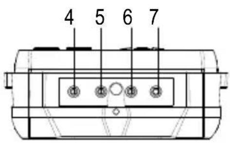
8.1 Product
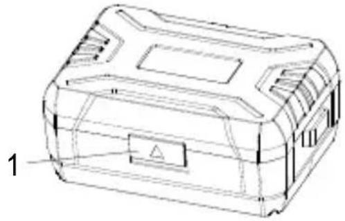
natural_image
Technical line drawing of a rectangular electronic device casing with internal compartments and a labeled component (no text or symbols present)- Cover lock
- USB communication port
- DC 5V/2A charging port
- C1 terminal (red: +)
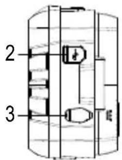
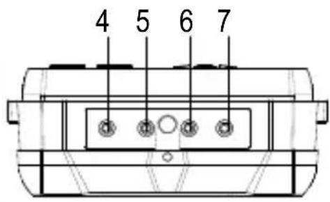
- P1 terminal (red: +)
- P2 terminal (black: -)
- C2 terminal (black: -)
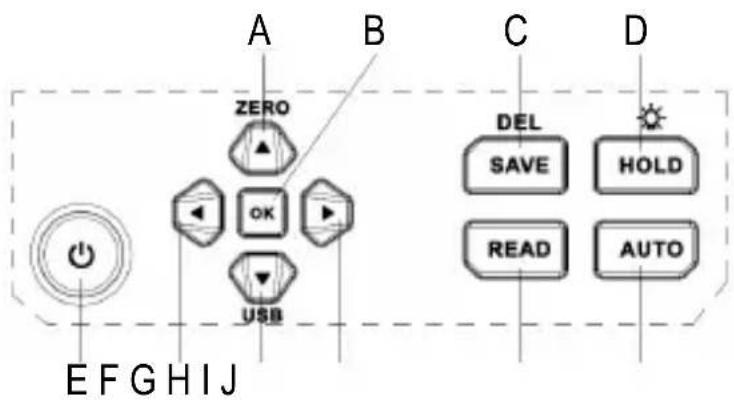
8.2 Function buttons
flowchart
graph TD
    A["Power Input"] --> B["OK"]
    B --> C["USB"]
    D["Input"] --> E["Power Supply"]
    F["Input"] --> G["Device Icon"]
    H["Device Icon"] --> I["Device Icon"]
    J["Device Icon"] --> K["Device Icon"]
    L["Device Icon"] --> M["Device Icon"]
    N["Device Icon"] --> O["Device Icon"]
    P["Device Icon"] --> Q["Device Icon"]
    R["Device Icon"] --> S["Device Icon"]
    T["Device Icon"] --> U["Device Icon"]
    V["Device Icon"] --> W["Device Icon"]
    X["Device Icon"] --> Y["Device Icon"]
    Z["Device Icon"] --> AA["Device Icon"]
    AB["Device Icon"] --> AC["Device Icon"]
    AD["Device Icon"] --> AE["Device Icon"]
    AF["Device Icon"] --> AG["Device Icon"]
    AH["Device Icon"] --> AI["Device Icon"]
    AJ["Device Icon"] --> AK["Device Icon"]
    AL["Device Icon"] --> AM["Device Icon"]
    AN["Device Icon"] --> AO["Device Icon"]
    AP["Device Icon"] --> AQ["Device Icon"]
    AR["Device Icon"] --> AS["Device Icon"]
    AT["Device Icon"] --> AU["Device Icon"]
    AV["Device Icon"] --> AW["Device Icon"]
    AX["Device Icon"] --> AY["Zero"]
A. Up/zeroing button
B. OK/confirm button
C. Data saving/deletion
D. Data hold/Backlight
E. POWER button
F. Left button
G. Down/USB communication button
H. Right button
I. Data reading
J. Auto/Manual mode switching
9 Display
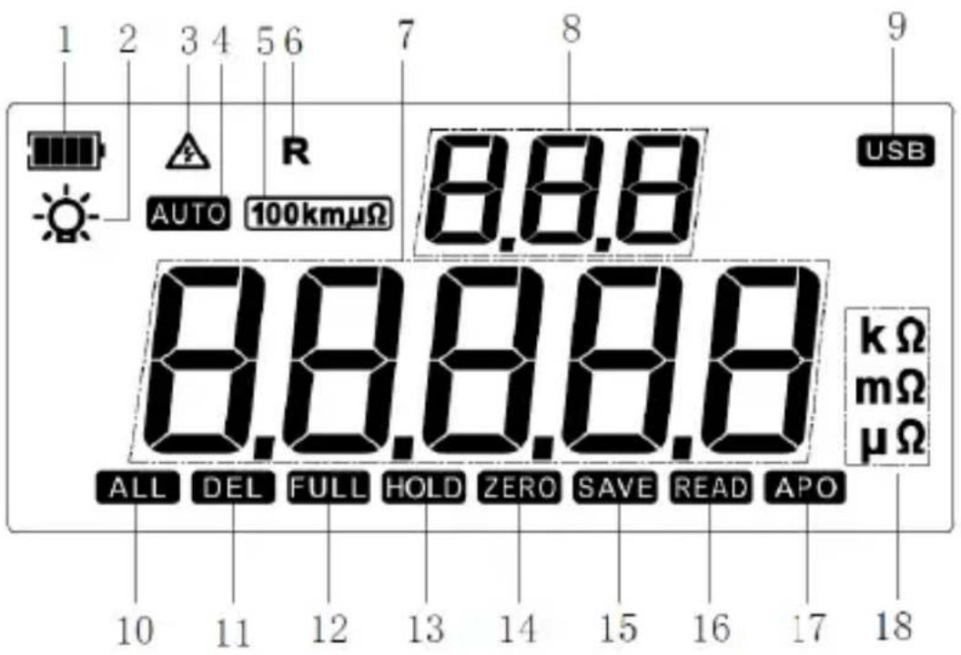
- Battery power indicator
- Backlight ON
- Dangerous operation (shows when measuring external AC current)
- Automatic measurement mode ON
- Current measurement position: 100 μΩ - 100 kΩ)
- Resistance measurement active
- Measured resistance
- Total number of saved data
-
USB communication active
-
All saved data is selected
- Data is to be deleted. Press "OK" to confirm deletion
- Data storage full
- Hold display active
- 1x flash to indicate zeroing is complete
- 1x flash each time data is saved
- Data reading mode active
- Auto power OFF active
- Unit of measured value
10 Recharge the battery
WARNING
To avoid electric shock remove the test leads before opening the battery compartment.

Low battery voltage can affect the accuracy of readings resulting in electric shock and/or injury.
If the product is not used for a long time, charge the battery once every 1 to 2 months
Recharge the batteries when low battery indicator shows “☐”
Proceed as follows to recharge the batteries:
√ The power is switched OFF.
√ The test leads are disconnected from the terminals.
- Connect the power adaptor to the DC 5V/2A port on the product and a suitable power ovutlet.
→ Charging will start on connection.
- Disconnect the charger when the charge status indicator is full.
- Replace the charging port cover.
11 Operation

Do not apply voltage to the input terminals: C1, P1, P2, C2
11.1 Power ON/OFF
Press and hold the button to switch the product ON/OFF.
The power will automatically switch off after approx. 15 mins of inactivity.
11.2 Precision resistance testing
WARNING
Please make sure that the object to be measured is not electrically charged and that the object to be measured is well connected to the test clamps before measuring the low value resistance.
When the low resistance measuring (<100Ω), to ensure the accuracy of measurement, a single measurement interval must not exceed 1 min.
- Switch the power on.
- Connect the test leads to the object under test.
- Disconnect the test leads and switch the power off after measurement.
Some application examples:
Measure the resistance of a resistor.
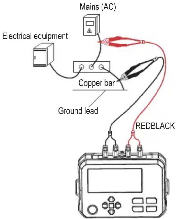
Test the resistance between an electric meter box, ground wire, and down conductor.
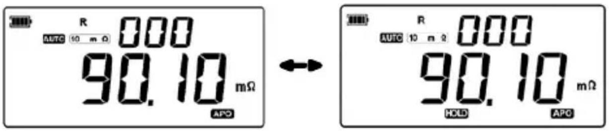
11.3 Data hold
Press the HOLD button to hold / release the measured value.
"HOLD" will appear on the display to indicate hold is active.
11.4 Data save
Press the SAVE button to save the displayed data.

11.5 Backlight ON/OFF
Press and hold the -button to switch the backlight on/off.
11.6 Automatic measurement mode
In this mode, the measurement position (range) is adjusted automatically.
- Press the AUTO button so that "AUTO" shows on the display.
→ You have entered automatic measurement mode.
11.7 Manual measurement mode
In this mode, the measurement position (range) is adjusted manually.
- Press the AUTO button until "AUTO" does not show on the display.
→ You have entered manual measurement mode.
- Press ▲ / ▼ to manually select a measurement range.
→ The selected range will show on the display.
11.8 Read saved data
- Press the READ button to enter data reading mode.
→ "READ" will appear on the display.
- Press ▲ / ▼ to scroll through single sets of data, or ◀ / ▶ button to shuffle through 10 sets of data each press.
→ If no data is saved, the display will show "NULL".
→ If the memory is full, the display will show "FULL".
11.9 Delete data

Always make sure any important data is backed up before deleting.
Delete single data point
- Select the data point you wish to delete. See: "11.8 Read saved data" on page 33.
- Short press the DEL button
→ The "DEL" icon will blink
-
Press the OK button to confirm deletion of the selected data.
-
Press and hold the SAVE button to exit delete mode.
Delete ALL data
-
Press the READ button to enter data reading mode.
-
Press and hold the SAVE button to delete all data.
→ The “ALL” and “DEL” icons will blink at the same time
- Press the OK button to confirm deletion of all data.
→ “NULL” will show on the display and delete mode will be exited.
12 PC connection
The PC software functions include data reading and saving.
Software download
Visit www.conrad.com/downloads and enter the Item number to find software.
Connect the product to a computer as follows:
- Connect the meter to a computer via USB-C® cable and port.
- Switch the power ON.
- Load the software on your computer.
-
After the software is running, press and hold the “▼” button to enter USB communication mode.
→ "USB" will appear on the display, confirming a successful connection. -
You are now connected to your PC
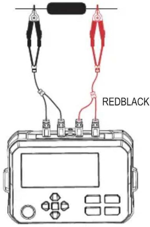
13 Lead resistance calibration
Lead resistance calibration is performed on a micro ohmmeter to eliminate the inherent resistance of the test leads and probes from the measurement, ensuring only the object's resistance is accurately measured.
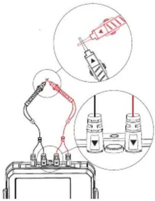
- Connect the test clips to the meter. The white arrows on the clips should align with the correct binding posts on the meter.
- Switch the meter on.
- Short-circuit the two test clips as shown.
- Wait for the displayed reading to stabilize.
- Press and hold the “▲” button (approx.3 seconds).
→ "ZERO" will appear to indicate lead resistance calibration is complete.
14 Troubleshooting
| Problem Possible cause Suggested solution | ||
| “OL” shows on the display and no resistance value is shown | Resistance value of the component exceeds the meter's measurement range | Select a higher resistance range on the meter (if manual range) or verify that the resistance is within the meter's specified limits |
| Test clips are loose, dirty, or not making proper contact with the resistor terminals | Ensure test clips are firmly attached and clean the connection points | |
15 Cleaning and care
Important:
- Do not use aggressive cleaning agents, rubbing alcohol or other chemical solutions. They damage the housing and can cause the product to malfunction.
- Do not immerse the product in water.

- Regularly check the product and test leads for damage.
Before cleaning:
- Disconnect all circuits and test leads.
- Switch the power OFF
- Disconnect the product from the power supply.
- Clean the product with a dry, fibre-free cloth.
16 Disposal
16.1 Product
This symbol must appear on any electrical and electronic equipment placed on the EU market. This symbol indicates that this device should not be disposed of as unsorted municipal waste at the end of its service life.
Owners of WEEE (Waste from Electrical and Electronic Equipment) shall dispose of it separately from unsorted municipal waste. Spent batteries and accumulators, which are not enclosed by the WEEE, as well as lamps that can be removed from the WEEE in a non-destructive manner, must be removed by end users from the WEEE in a non-destructive manner before it is handed over to a collection point.
Distributors of electrical and electronic equipment are legally obliged to provide free take-back of waste. Conrad provides the following return options free of charge (more details on our website):
in our Conrad offices
at the Conrad collection points
at the collection points of public waste management authorities or the collection points set up by manufacturers or distributors within the meaning of the ElektroG
End users are responsible for deleting personal data from the WEEE to be disposed of.
It should be noted that different obligations about the return or recycling of WEEE may apply in countries outside of Germany.
16.2 (Rechargeable) batteries
Remove batteries/rechargeable batteries, if any, and dispose of them separately from the product. According to the Battery Directive, end users are legally obliged to return all spent batteries/rechargeable batteries; they must not be disposed of in the normal household waste.
Batteries/rechargeable batteries containing hazardous substances are labelled with this symbol to indicate that disposal in household waste is forbidden. The abbreviations for heavy metals in batteries are: Cd = Cadmium, Hg = Mercury, Pb = Lead (name on (rechargeable) batteries, e.g. below the trash icon on the left).
Used (rechargeable) batteries can be returned to collection points in your municipality, our stores or wherever (rechargeable) batteries are sold. You thus fulfil your statutory obligations and contribute to environmental protection.
Batteries/rechargeable batteries that are disposed of should be protected against short circuit and their exposed terminals should be covered completely with insulating tape before disposal. Even empty batteries/rechargeable batteries can contain residual energy that may cause them to swell, burst, catch fire or explode in the event of a short circuit.
17 Technical data
17.1 Power adaptor
| Manufacturer | Conrad Electronic SE, Klaus-Conrad-Str. 1, 92240 Hirschau, Germany |
| Commercial Registration Number HRB | 3896 |
| Model identifier XZF-A0502000-H | |
| Input voltage 100–240 V/AC | |
| Input AC frequency 50/60 Hz | |
| Output voltage 5.0 V/DC | |
| Output current 2.0 A | |
| Output power 10.0 W | |
| Average active efficiency 78.9 % | |
| Efficiency at low load (10 %) exempt | |
| No load power consumption 0.08 W |
17.2 Product
Rechargeable battery 3.7 V 3200 mAh 11.84 Wh Li-ion
Power consumption (standby) ....<130 mA connected to test clip)
Protection class ...... II
Ingress protection....IP54
Testing method 4-wire method
Testing current....≤1A
Open-circuit voltage....≤4.2V
Measurement power....<8 W
Display backlight.....yes
Measurement speed....approx. 2x per sec
USB-C® port...... data transfer
Data storage 499 readings
Overrange indication ...... “OL” is displayed
Auto power off ....approx. 15 minutes of inactivity
Operating temperature ...... -10 to +50 °C
Storage temperature....-20 to +60 °C
LCD dimension (L x W).... 102 x 50 mm
Dimensions (W x H x D) 161 x 117 x 68 mm
Weight 480 g
Applicable standards .... IEC61010-1
17.3 Test leads
Applicable standard....IEC/EN 61010-031
Length..... approx. 85 cm
18 Specifications
18.1 Accuracy
Ambient temperature: 23 ±5 °C
Ambient humidity: 45\~75% RH
External magnetic field: None (Earth's magnetic field).
Battery voltage: Available effective battery voltage.
Temperature coefficient: A testing error of ±0.01% will be added per degree.
(Celsius) if test is performed in temperature of >28 ^ or <18 ^ .
18.2 Range and accuracy
| Range Resolution Testing current (max.) | ||
| 0.001 mΩ~10.000 mΩ 0.001 mΩ 1 A | ||
| 10.01 mΩ~100.00 mΩ 0.01 mΩ 1A | ||
| 100.1 mΩ~1000.0 mΩ 0.1 mΩ 100 mA | ||
| 1.001 Ω~10.000 Ω 0.001 Ω 10 mA | ||
| 10.01 Ω~100.00 Ω 0.01 Ω 1 mA | ||
| 100.1 Ω~1000.0 Ω 0.1 Ω 100 μA | ||
| 1.001 KΩ~10.000 kΩ | 0.001 kΩ | 10 μA |
| 10.01 KΩ~100.00 kΩ | 0.01 kΩ | 10 μA |
| 100.1 KΩ~300.0 kΩ 0.1 kΩ | 3 μA | |
18 to 28 °C; 75 % RH: ±(0.1 % FS +20 dgt)
1 Ω (ohm)=1000 mΩ
Overrange indication: "OL" is displayed if the measurement range is exceeded.
natural_image
Technical line drawing of a mechanical housing or enclosure with internal compartments and a labeled component (no text or symbols present)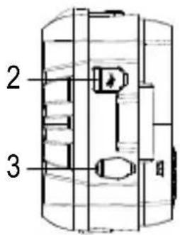
14 Dépannage
Dimensions (L x H x P)....161 x 117 x 68 mm
Poids....480 g
Normes applicables......CEI 61010-1
3 Beoogd gebruik
natural_image
Technical line drawing of a mechanical housing or enclosure with internal compartments and a labeled component (no text or symbols present)11.1 Voeding AAN/UIT
14 Probleemoplossing
- Problemlösung
- Operating Instructions for download
- Intended use
- Ingress protection:
- Features and functions
- Delivery content
- Description of symbols
- Safety instructions
- General information
- Handling
- Operating environment
- Operation
- Li-ion battery
- Power adaptor
- Connected devices
- Testing and measurement
- Low resistance measurement precaution
- WARNING
- Test leads
- Product overview
- Product
- Function buttons
- Display
- Recharge the battery
- Operation
- Power ON/OFF
- Precision resistance testing
- Data hold
- Data save
- Backlight ON/OFF
- Automatic measurement mode
- Manual measurement mode
- Read saved data
- Delete data
- Delete single data point
- Delete ALL data
- PC connection
- Software download
- Lead resistance calibration
- Troubleshooting
- Cleaning and care
- Important:
- Disposal
- Product
- (Rechargeable) batteries
- Technical data
- Power adaptor
- Product
- Test leads
- Specifications
- Accuracy
- Beoogd gebruik
- Voeding AAN/UIT
- Probleemoplossing
Brand : VOLTCRAFT
Model : R-1000
Category : Measuring equipment