
VC-55 LCD SE - Measuring equipment VOLTCRAFT - Free user manual and instructions
Find the device manual for free VC-55 LCD SE VOLTCRAFT in PDF.

| Product type | Bipolar voltage detector |
| Brand | Voltcraft |
| Model | VC-55 LCD SE |
| Order number | 1603401 |
| Power supply | 2 micro AAA/LR03 batteries (1.5 V) – rechargeable batteries not allowed |
| Voltage range | 12 to 690 V AC/DC |
| Display | LCD screen with real-time voltage indicator; 7 LED levels (12, 24, 50, 120, 230, 400, 690 V) |
| Main functions | Bipolar voltage detection, audio/visual continuity test, unipolar phase tester, rotary field direction indicator, LED illumination of measurement points |
| Measurement category | CAT III 1000 V, CAT IV 600 V |
| Protection rating | IP64 (dust and water splashes) |
| Operating temperature | -15 °C to +55 °C |
| Relative humidity | 85% max., non-condensing |
| Operating altitude | Up to 2000 m |
| Max. test current | < 3.5 mA |
| Acoustic signal | From 38 V AC / 120 V DC (works even without batteries) |
| Max. operating time | 30 seconds (240 seconds break mandatory) |
| Compliance | EN 61243-3 / DIN VDE 0682-401 |
| Maintenance and cleaning | Clean with a soft, damp cloth; do not use abrasive or chemical cleaners |
| Spare parts / accessories | Batteries (ref. 652303), plastic protective sleeves, 4 mm screw contacts, probe tip protectors |
| Warranty | Statutory warranty of conformity (2 years) |
Frequently Asked Questions - VC-55 LCD SE VOLTCRAFT
User questions about VC-55 LCD SE VOLTCRAFT
0 question about this device. Answer the ones you know or ask your own.
Ask a new question about this device
Download the instructions for your Measuring equipment in PDF format for free! Find your manual VC-55 LCD SE - VOLTCRAFT and take your electronic device back in hand. On this page are published all the documents necessary for the use of your device. VC-55 LCD SE by VOLTCRAFT.
USER MANUAL VC-55 LCD SE VOLTCRAFT
The two-pole voltage tester is a portable test device that detects and indicates the voltage levels of low voltage circuits. It is intended to indicate DC and AC voltages in the range of 12 to 690V , and polarity by applying bipolar. The voltage ranges are represented in 7 levels.
Starting at a nominal voltage of 38 V/AC or 120 V/DC, a warning indicator for the voltage ranges will flash signaling the warning of dangerous voltage. This warning indication is also displayed when the batteries are empty.
The voltage tester complies with the standard for two-pole voltage testers (EN 61243-3/DIN VDE 0682-401) and protection type IP64 (dust and splash proof), and is intended for dry or damp indoor and outdoor locations. Operating the device during rainfall or precipitation is not permitted. The voltage tester is designed for use by qualified electricians in conjunction with personal protective equipment.
The device features an LCD display with an indicator of the test voltage real value, an audio-visual continuity tester, built-in measurement point light and the function "single pole" phase tester. For the tester to function two micro batteries (type AAA/LR03) are required. Operation with rechargeable batteries is not permitted.
A phase sequence indicator for grounded three-phase current is available.
The voltage tester shall only be utilized in systems of the electrical measurement category CAT III (domestic installations / sub-distributions) up to 1000 V or in CAT IV (at the origin of the low-voltage installations) up to 600 V to ground potential.
These measurement categories also comprise all of the smaller measurement categories (e.g. CAT II and CAT I).
The voltage tester must be clasped by the two handles (1 and 16) while taking measurements. Do not touch beyond the tactile barriers of the gripping area (5 and 13). Do not cover the indicator panel and do not touch metal contacts and measurement points.
Follow also any additional safety instructions contained in this manual.
Do not use under adverse ambient conditions. Unfavourable ambient conditions are:
- Excessive humidity or dampness
- Dust and flammable gases, vapours or solvents
- Potentially explosive atmosphere (Ex)
- Thunderstorms or similar weather conditions such as strong electrostatic fields, etc.
Use other than that described above can lead to damage to the product and may involve additional risks such as, for example, short circuits, fire, electrical shocks etc. No part of the product may be modified or converted! The safety instructions are to be observed without fail
Package contents
VC-55 LCD SE with captive probe tip protection
- 2 terminal screws (Ø 4 mm, applicable for CAT II)
- 2 plastic protective sheaths, applicable for CAT III/CAT IV
- 2 micro batteries (AAALR03)
- Operating instructions

Up-to-date operating instructions
Download the latest operating instructions via the link www.conrad.com/downloads or scan the QR code. Follow the instructions on the website
Symbol explanation
An exclamation mark in a triangle indicates important information contained in these operating instructions that must be observed by all means.
The lightning symbol in a triangle warns of electric shock danger or the impairment of the electrical safety of the appliance.
This device is CE compliant and therefore meets the necessary national and European guidelines.
The arrow symbol is used where special tips and notes on operation are provided.
Safety instructions and hazard warnings
This device has left our factory premises in a safe and perfect condition.
We kindly request the user to observe the safety instructions and warnings contained in the enclosed operating instructions so this condition is maintained and to ensure safe operation.
- Damages due to failure following these operating instructions will void the warranty! We do not assume any liability for any resulting damage!
- We do not assume any liability for personal injuries and material damages caused by the improper use or non-compliance with the safety instructions! Any warranty will be void in such cases.
- The unauthorised conversion and/or modification of the unit is not permitted for safety and approval reasons.
- For any work carried out, the accident prevention regulations of the Employer's Liability Insurance Association for Electrical Systems and Operating Facilities must be observed
- In schools, training facilities, hobby and self-help workshops the use of gauges and testers should be supervised in a responsible manner by qualified trained staff.
- Extra care should be taken when using the device for the first time. Therefore, please follow the operating instructions carefully.
- The voltage values specified on the voltage tester are nominal voltages.
- The device may not be exposed to extreme temperatures, strong vibrations or high humidity. The readout is only ensured within a temperature range of -15 to +55 °C and a relative air humidity of max. 85% (non-condensing).
- Hold the voltage tester only by the designated gripping areas (1 and 16). Never reach beyond the tactile barrier of the gripping areas (5 and 13).
- Always check that the voltage tester is working properly prior and after employment. Measure a known voltage source (e.g. mains voltage 230 V/AC) first, and check the accuracy of the readout. Don't use the voltage tester any longer, in case one or more indication ranges fail to function.
- The housing of the voltage tester may not be disassembled except for opening the battery compartment cover.
- The voltage tester may only be used on systems within the voltage ranges given.
- The next higher voltage range on the level indicator starts at 0.85 times the nominal value already.
- The applicable DC voltage limit value for hazardous contact voltage (in accordance with DIN VDE 0100, part 410) is indicated by the light indicator at 120V .
The applicable DC voltage limit value for hazardous contact voltage (in accordance with DIN VDE 0100, part 410) is indicated by the light indicator at 50V .
- The voltage tester only works correctly on grounded low voltage systems. Improper grounded equipment or insulated body protectors can have an adverse effect on the readout.
- If the neutral wire (N) or the earth wire (PE) is interrupted, no readout will be displayed!
- Keep the voltage tester in a clean condition, and store it properly in a dry place.
- This device is not a toy and should be kept out of the reach of children.
- To prevent injuries place the probe tip protection back on the test probes, if the tester is not used.
- When using the voltage tester in the range of the measurement categories CAT III and CAT IV, it is recommended to push the included plastic protective sheath (2) over the test probes in order to reduce the exposed length of contact tips. This will reduce the risk of a possible short circuit during metering.
- Depending on the internal impedance of the voltage tester, there are different ways of displaying "operating voltage present" or "operating voltage not present" in the presence of interference voltage.
- A voltage tester with relatively low internal impedance does not display all interference voltages with an initial value above ELV, compared to the reference value of 100k Upon contact with the parts to be tested, the voltage tester may temporarily reduce the interference voltage by discharging to a level below ELV; however, after removing the voltage detector, the interference voltage will assume its original value again.
- When the notification "voltage present" does not appear, it is strongly recommended that you insert the earthing device before starting work.
- A voltage tester with relatively high internal impedance will not clearly display "operating voltage present" in the event of existing interference voltage, compared to the reference value of 100k
- When "voltage present" appears on a part which is considered disconnected from the system, it is strongly recommended to check the state "operating voltage not present" with additional measures (e.g., using a suitable voltage tester, visual inspection of the disconnection point in the electrical network, etc.) to make sure the voltage indicated by the voltage tester is not a fault.
- A voltage tester indicating two values of the internal impedance has passed the design test for handling interference voltages and is able to differentiate (within technical limits) the operating voltage from the interference voltage and directly or indirectly display the existing voltage type.
CATI
Measurement Category I is applicable to measuring circuits of electrical and electronic equipment that is not directly supplied with mains voltage (battery-operated devices, etc.)
CAT II
Measurement Category II is applicable to measuring circuits of electrical and electronic equipment that is directly supplied with the mains voltage via a power plug. This category also covers all smaller categories (e.g. CAT I for measuring signal and control voltages).
CAT III
Measurement Category III is applicable to measuring circuits of installations in buildings (e.g. electric sockets or sub-distributions). This category also covers all smaller categories (e.g. CAT II for measuring electronic devices).
Measurement Category IV is applicable to measuring at the origin of the low-voltage installation (e.g. main distribution, electricity provider's transfer points to homes, etc.) and outdoors. This category also contains all lower categories.
Please pay attention to the following symbols and labels:
| L1 - Probe for phase | L1, negative potential at DC |
| L2 + Probe for phase | L2, single pole phase test, positive potential at DC |
| V AC DC | V AC = alternating current V DC = direct current |
| Display + Positive | potential at probe L2 + |
| Display - Negative | potential at probe L2 + |
| Display + - AC voltage (both indicators for + and - are on) | |
| 12/24/50/120 230/400/690 | Display of rated voltage range in volt (V) |
| Rx Display for continuity test | |
| kΩ Electrical resistance in kilo-ohm | |
| f Rated frequency | range of electr. voltage |
| I Test current is specified in mA (milliampere) | |
| W Electrical test load in watts | |
| Hz Electrical frequency (Hertz) | |
| Temp °C Permitted operating temperature range in ° Celsius | |
| ON Maximum duty cycle (DC) in seconds (s) | |
| OFF Minimum operating pause after a test cycle in seconds (s) | |
| Date Year of manufacture | |
| OL Overflow indication. Measuring range exceeded | |
| ---- | Power indicator on the display |
| A | Warning of hazardous voltage (>38 V/AC, >120 V/DC (also functions when batteries are empty or even without batteries). |
| ●● | Symbol for buzzer alarm |
| A | Apparatus and equipment for live works. Personal protective measures are essential. |
| ○○ ○R | Rotary direction field indicator on grounded three-phase networks. L = left turning, R = right turning |
| ○ | Protection class 2 (double or reinforced insulation/protective insulation) |
| ○+ | Symbol for the battery data used. 2x 1.5 V micro batteries, LR03, AAA |
| ○- | Replace battery indicator on display. The batteries must be replaced immediately, if this symbol appears. |
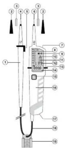
Description of component parts
1 Handle probe tip L1 (-)
2 plastic protective sheaths, applicable for CAT III/CAT IV
3 4 mm terminal screws to test outlets from the front side (built-in outlet! CAT II)
4 Probe tip L1 (-)
5 Hand grip barrier with fastening bar
6 Probe lip L2 (+)
7 LED measurement point light
8 LED level indicator for voltage ranges and polarity
9 Covered sound opening for alarm buzzer
10 Warning of hazardous voltage (>38V / AC, > 120V / DC (also indicated when batteries are empty or even when no batteries are present). Phase indicator for single-pole phase test
11 Rx indicator for continuity test
12 Rotary direction field indicator (L = left turning/ = right turning)
13 Handle grip barrier
14 LCD screen for nominal voltage indicator and battery replacement indicator
15 Button for LED metering point light
16 Handle probe tip L2 (+)
17 Battery compartment with bayonet lock
18 Connecting cable
19 Probe tip protection
Inserting/replacing the batteries
The voltage tester needs battery power for its basic function as a two-pole voltage tester with a voltage range indicator and its additional functions such as metering point light, continuity test, phase sequence indication or "single pole" phase tester. Two micro batteries (type AAA/LR03, included in delivery) are required for this purpose. The use of rechargeable batteries is not permitted.
To insert/replace the battery, proceed as follows:
- Remove the voltage tester from all metering points and attach the protective cover to the probes.
- Open the battery compartment (17) by releasing the lock with a flat object (e.g. wide slot screwdriver) in a 90^ counter-clockwise rotation. At its side, a small groove is exposed that allows you to remove the battery compartment cover from the device.
- Insert two new micro-batteries (LR03/AAA) into the battery compartment. Pay attention to the polarity indicated on the battery compartment cover. If possible, use alkaline batteries. They guarantee a longer service life.
- Close and lock the battery compartment in reverse order. Make sure that the sealing ring on the battery compartment does not get pinched or damaged. There is only one position for the battery compartment cover to match the device. The groove must be located on the right.
Battery replacement is necessary when the level indicator (8) is no longer illuminated during the function test, or the battery replacement symbol appears on the LCD, or if you cannot hear the signal sound any longer, when the contacts of the two probes (4 and 6) are in contact.

When the batteries are empty, only the warning indicator (10) for "Dangerous Voltage" will function when the test voltage reaches 38 V/AC or 120 V/DC. Do not ever touch the measuring contacts, if this indicator is on.
Operation while the battery compartment is open, is not permitted.
To prevent damage to the device from leaking batteries, remove the batteries from the device if you will not be using it for a longer period. For the same reason, we recommend that you remove flat batteries immediately.

Compatible alkaline batteries can be obtained with the following order number: Item no. 652303 (2 pcs. Please order 1x unit).
Only use alkaline batteries; they are high-performance and durable.
Mesurement points illumination
The VC-55 LCD SE has a battery-operated measuring point illumination.
Press button (15) to turn illumination on and off. The light is on for about 130 seconds and disappears automatically.
Performing tests and measurements
The two-pole voltage tester consists of the two probes (4 and 6), a connecting cable (18) and the indicator panel.
Always hold the voltage tester in a way, that you can look down onto the indicator panel. Illuminated indicators may be adversely affected by strong light.
For DC measurements, the probe tip L2+ (6) is the positive pole, and the probe tip L1- (4) is the negative pole.
The VC-55 LCD SE will autonomously turn on when the test starts (entry level >10V ), and when the test has been completed, it turns off.

Always check that the voltage tester is functioning properly prior and after employment. Measure a known voltage source (mains voltage 230 V/AC, for example) first, and check the accuracy of the readouts. In the event of one or more indicating ranges (8) fail, do not use the voltage tester. If the meter does not display any function or individual indicator ranges are not functioning, decommission the voltage tester. A defective voltage tester must not be used.
Observe the regulations regarding work with electrical systems. Personal protective equipment must be used when working on systems with dangerous electrical voltage.
The maximum permitted duty cycle (ON) is 30 seconds. After that time has passed, an operational rest of 240 minutes at least, has to be maintained.
When the indication "voltage present" appears on a part that is expected to be disconnected of the installation, it is highly recommended confirming by another means (e.g. use of an adequate voltage detector, visual check of the disconnecting point of the electric circuit, etc.) that there is no operating voltage on the part to be tested and to conclude that the voltage indicated by the voltage detector is an interference voltage.
When the indication "voltage present" does not appear, it is highly recommended installing earthing equipment before work.
The following measurement functions can be conducted:
a) Two-pole voltage metering
Always hold the voltage tester by the handles designed for this purpose (1 and 16). Never reach beyond the tactile barrier of the grip (5 and 13).
Guide the two probe tips onto the measurement points to be tested. The voltage range is shown on the level indicator (8) and the present measuring voltage is shown on the LCD display.
The light indicators (+) and (-) show the type of voltage and the corresponding polarity. If both indicators, LED (+) and (-) are lit at the same time, alternating current (AC) is present. Polarity is only indicated by means of the two LEDs.
At a voltage of about 38 V/AC or 100 V/DC a signal sound is produced. The rotating field indicator "L" and "R" may flash during metering. This is a technical issue and is without significance or impact on the measuring process.
The two probe tips L1 und L2 can be connected to one another, laterally via the fastening clamp on the handle grip barrier of probe tip L1 (5).
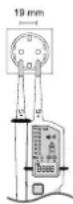
The distance between the two probes is 19mm , which complies with the standardized contact gap for EU and safety socket outlets.
In addition, establishing contact inside the outlets is made even easier when the included 4 mm adapter screws are used. That way, the voltage tester can be guided by using one hand only.
Make sure that your hand remains within the grip area (16) of probe tip L2 and that you don't cover the display.
b) Rotating field indicator
VC-55 LCD SE shows the rotating field direction of properly grounded three-phase systems (with batteries only). The voltage tester detects the order of increasing phases to ground potential
Hold the voltage tester by the handles (1) and (16) provided. Never touch the device beyond the handle ends.
Connect the two probes to the measuring points that you want to measure.
The probe L1 (4) corresponds to the outer cable (phase) L1.
The probe L1 (6) corresponds to the outer cable (phase) L2.
The available voltage range and the phase sequence is represented on the display.
The illuminated indicators (12) show the applicable rotating field direction (L = left turning / R = right turning)
Example 1: Example 2:
Probe tip L1 to outer cable L1, probe tip L1 to outer cable L2,
Probe tip L2 to outer cable L2, probe tip L2 to outer cable L3,
The correct field rotation "R" is displayed The correct field rotation *R' is displayed
Example 3:
Probe tip L1 to outer cable L2,
Probe tip L2 to outer cable L1,
Opposite phase sequence "L" is displayed
c) Continuity test
When batteries are inserted, the VC-55 LCD SE can be used as a continuity tester.
Hold the voltage tester by the handles (1) and (16) provided. Never touch the device beyond the handle ends.
Check function before your start metering.
Connect both probe tips to one another. A signal sounds and the display is illuminated (11).
If this is not the case, replace the batteries as described under "Inserting/Replacing the Batteries".
The continuity tester indicates a resistance of about 0 - 500k (+50%) as continuity.
d) Single-pole phase test
When batteries are inserted, the VC-55 LCD SE can be used as a single-pole phase tester.
Hold the voltage tester by the handles (1) and (16) provided. Never touch the device beyond the handle ends.

This single-pole phase test serves as a quick test only, and prior to any work conducted on this line the absence of voltage must be rechecked using the double-pole measuring method. Observe the regulations regarding work with electrical systems.
Contact probe tip L2 with the measuring point to be tested. Probe L1 has no contact.
If an alternating voltage >100V is present, the indicator (10) lights up and a signal sounds.

The single-pole phase display may be adversely affected by unfavourable ambient conditions (electrostatic fields, good insulation etc.). However, perform an additional double-pole voltage test to determine that voltage is absent.
Cleaning and maintenance
Besides occasional cleaning and battery replacement, the voltage tester is maintenance-free.
The voltage tester must be disconnected from all devices under test before cleaning.
After cleaning, allow the product to dry completely before using it again.
Never try to open the housing, apart from the battery compartment.
Check the technical safety of the voltage tester regularly. It is understood that safe operation is no longer possible:
- if the device or he connecting cable is visibly damaged
- after prolonged storage under unfavourable conditions
- after extraordinary transport stress
The outside of the device should be cleaned with a soft, damp cloth or brush only. Do not use abrasive or chemical cleaning agents which could damage the housing or impair operation.
Disposal
a) General

Electronic products are recyclables and do not belong in the household waste. When the device has reached the end of its service life, please dispose of it, according to the current statutory requirements, at your local collecting site. It is prohibited to dispose of the device with domestic waste.
b) Batteries
You as the ultimate consumer are legally obliged (Regulation on Spent Batteries) to return all dead batteries; disposal in the household waste is prohibited!
Batteries containing hazardous substance are marked by the symbols alongside which indicates the prohibition of disposal with domestic waste. The symbols of the relevant heavy metals are: Cd = Cadmium, Hg = Mercury, Pb = Lead. You can hand in your used batteries at the collection points of your community at no cost or everywhere where batteries/accumulators are sold.
Thus you fulfil your statutory obligations and contribute to the protection of the environment!
Technical data
a) General information
Voltage indicator LED. 12, 24, 50, 120, 230, 400, 690 V AC/DC
Voltage indicator LCD. 12 - 690 V AC/DC
Resolution LCD 0.1 V
Polarity indicator. +,-, + / - (AC)
Indicator tolerance LCD. ± (3% +5 counts)
Indicator tolerance LED.. according to EN61243-3
Voltage display automatic
Signal. 38 V, continuity
Display delay. <1 s LED
Frequency range f. DC, 16 ... 400 Hz
Power input.. approx. 2.4 W at 690 V
Max test current I. .<3.5 mA
Warning indicator LED. >38 V/AC, >120 V/DC
Measuring time / cycle.. max. 30 seconds
Rest time 240 seconds
LED/LCD indicator from. >10VAC/DC
Power supply. 2x 1.5 V (AAA/LR03)
Battery power supply.. approx. 80 mA
Temperature range operation -15 to +55^
Storage temperature. -20 to +70^
Rel. Humidity max. 85% non-condensing
Measurement category...CATIII 1000 V, CAT IV 600 V
Pollution degree. 3
Operating altitude. max. 2000 m above N.N.
Protection type.. IP64
b) Rotating field direction indicator only on grounded three-phase syste
Voltage range 120 - 400 V/AC
Frequency range 50/60 Hz
c) Continuity test
d) Single-pole phase test
Test range. 0 - 500k (+50%)
Overvoltage protection 690 V DC/AC
Voltage range 100-690 V/AC
Frequency range 50/60 Hz
Mode d'emploi
Indicatevertraging. <1sLED
Frequentriebereik f. DC, 16 ... 400 Hz
- Package contents
- Up-to-date operating instructions
- Symbol explanation
- Safety instructions and hazard warnings
- CATI
- CAT II
- CAT III
- Description of component parts
- Inserting/replacing the batteries
- To insert/replace the battery, proceed as follows:
- Mesurement points illumination
- Performing tests and measurements
- a) Two-pole voltage metering
- b) Rotating field indicator
- c) Continuity test
- d) Single-pole phase test
- Cleaning and maintenance
- Disposal
- a) General
- b) Batteries
- Technical data
- a) General information
- b) Rotating field direction indicator only on grounded three-phase syste
- Mode d'emploi
Brand : VOLTCRAFT
Model : VC-55 LCD SE
Category : Measuring equipment