Freevia Essential - Garage door opener SOMFY - Free user manual and instructions
Find the device manual for free Freevia Essential SOMFY in PDF.
| Product Type | Sliding garage door opener |
| Brand | Somfy |
| Model | Freevia Essential |
| Power supply | 230 V - 50 Hz or 24 V (solar) |
| Motor power | 120 W |
| Maximum power consumption | 600 W (with zone lighting) |
| Standby consumption | 0.21 W |
| Operating frequency | 433.42 MHz (< 10 mW) |
| Radio range | Approx. 30 m |
| Compatible gate | Sliding PVC, wood or metal |
| Maximum gate length | 7 m (Freevia Line) / 6 m (Freevia 400 / Origin) |
| Maximum gate weight | 500 kg (Freevia Line) / 400 kg (Freevia 400 / Origin) |
| Operating temperature | -20 °C to +60 °C |
| Protection index | IP 44 |
| Insulation class | Class 1 |
| Maximum number of remote controls | 16 |
| Flashing light output | 24 V, 10 W max |
| Zone lighting output | 500 W max at 230 V |
| Accessory power output | 24 Vdc / 15 W max |
| Obstacle detection | Automatic, compliant with EN 12453 |
| Thermal protection | Yes |
| Backup battery | Optional, autonomy 10 cycles or 24 h |
| Maintenance | Disconnect power before cleaning; replace remote battery every 2 years |
| Warranty | Refer to manual or Somfy website |
Frequently Asked Questions - Freevia Essential SOMFY
User questions about Freevia Essential SOMFY
0 question about this device. Answer the ones you know or ask your own.
Ask a new question about this device
Download the instructions for your Garage door opener in PDF format for free! Find your manual Freevia Essential - SOMFY and take your electronic device back in hand. On this page are published all the documents necessary for the use of your device. Freevia Essential by SOMFY.
USER MANUAL Freevia Essential SOMFY
text_image
Diagram illustrating the assembly of a battery pack with labeled components and directional arrows indicating flow or movement.text_image
Diagram of a wall assembly with labeled components A through J, showing structural connections and components.text_image
G F E D B A somfy. RESET P1 30s RADIO connects with Somfy TaHomatext_image
Diagram showing three scenarios of building inspection with checkmarks and a red X mark, likely indicating failure or invalid status.natural_image
Technical line drawing of a mechanical device with an arrow indicating rotation or movement (no text or symbols present)text_image
Diagram showing various tools and components with numbered labels, likely for assembly or repair instructions.
natural_image
Diagram showing a tool interacting with a mechanical component, no text or symbols presentnatural_image
Technical line drawing of a mechanical assembly with bolts and a central component (no text or symbols)natural_image
Diagram of a curved mechanical component with an arrow indicating direction (no text or symbols)natural_image
Four circular icons showing different types of tools: pencil, tool, drill bit, and wrench (no text or symbols)!
natural_image
Technical line drawing of a mechanical device with no visible text or symbolsnatural_image
Technical line drawing of a mechanical assembly with no visible text or symbolsnatural_image
Technical illustration of a mechanical assembly with rollers and a gear mechanism, showing alignment and assembly details (no text or symbols)natural_image
Diagram of a mechanical device with an arrow indicating rotational motion (no text or symbols)natural_image
Four circular icons showing different types of tools: screwdriver, pliers, screwdriver with cross symbol, and a circle with a minus sign (no text or labels)
natural_image
Technical line drawing of a mechanical assembly with no visible text or symbolsnatural_image
Technical diagram of a mechanical assembly with labeled parts and a magnified inset showing internal components (no readable text or symbols)natural_image
Technical line drawing of a mechanical device with no visible text or symbolstext_image
Diagram showing a device control panel with labeled buttons and a hand pointing to the right button, indicating a function or operation.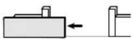


text_image
Technical diagram of a mechanical component with labeled parts and directional arrows indicating assembly or assembly steps.
text_image
Technical diagram of a mechanical component with labeled parts and directional arrows indicating assembly or assembly steps.natural_image
Illustration of a gray remote control device with wireless signal waves and a 'somy' logo (no text or symbols on the device itself)
text_image
STOPtext_image
>2s RADIO P1 RESET somfy.natural_image
Technical line drawing of a mechanical assembly with cylindrical components and internal components (no text or symbols)
text_image
BATT - +text_image
entation BATT - +natural_image
Diagram showing a hand interacting with a rectangular block and a right-hand block, illustrating a process or interaction (no text or symbols present)text_image
RADIO P1 RESET somfy. Somfy ToHometext_image
RADIO P1 RESET somfy. Somfy TaHomanatural_image
Technical line drawing of a mechanical device with no visible text or symbolstext_image
RADIO 30% P1 RESET somfy.
text_image
7 RADIO P1 RESET x2 RADIO P1 RESET somfy. somfy.natural_image
Mechanical device with a lever and connector, shown in a magnified inset (no text or symbols visible)natural_image
3D illustration of a device with a circular component and directional arrows indicating motion (no text or symbols)natural_image
Close-up of a computer mouse with a small circular button and a magnified view showing a small electronic device (no text or symbols visible)natural_image
Close-up of a computer mouse with a cursor pointing to the internal panel (no text or symbols visible)natural_image
Diagram of a mechanical device with a rotating shaft and curved arrow indicating rotation (no text or symbols)natural_image
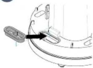
Diagram showing a device being placed into a closed housing, with an arrow indicating the process (no text or symbols present)natural_image
Diagram of a smartphone showing internal components and a coin with an arrow, no text or symbols present- Remplacer la pile (3 V CR 2430 / CR 2032).

natural_image
3D mechanical assembly diagram showing a device with mounting holes and internal components (no text or symbols)- Pack contents 2
- Space requirements 3
- Field of application 3
- Overview of the installation 3
- Control electronics description 4
Prerequisites for installation 5
- Ground stop blocks (not supplied) 5
- Positioning the motor 5
- Electrical pre-equipment 5
- Cables required 6
-
Concrete base 7
-
Tools required for installation (not supplied) 8
- Fasteners required for rack installation (not supplied) 8
Installation 9
1.1 Unlocking the motor 9
1.2 Installing the motor 9
- Anchoring the motor in the ground 9
- Fastening the rack 10
1.3 Checking the motor installation 11
1.4 Locking the motor 12
1.5 Wiring the motor 12
1.6 Connecting to the 230V mains power supply 13
1.7 Earthing the control electronics 14
1.8 Position of the control electronics antenna 14
Commissioning and standard use 15
2.1 Powering on the installation 15
2.2 Gate travel auto-programming 15
2.3 Control electronics standby / reactivation 16
2.4 Plugging the openings 16
2.5 Fitting the cover 16
2.6 Fully opening and closing the gate 17
2.7 Obstacle detection 17
Wiring the accessories 18
3.1 Photoelectric cells 18
- Installation 18
- Cell recognition by the motor electronics in normal operating mode 18
3.2 Flashing light 19
- Flashing light operation 19
- Operation with photoelectric cells 19
- In the event of photoelectric cell removal 19
3.3 Battery 20
3.4 Remote antenna 20
3.5 Video door phone 21
3.6 Key contact 21
3.7 Area lighting 21
3.8 Solar power 21
- Lighting output power 21
- Area lighting operation 21
Advanced parameter settings 22
4.1 Pedestrian opening 22
- Pedestrian opening operation 22
- Activating pedestrian opening 22
- Deactivating pedestrian opening 22
4.2 Automatic closing 23
- Automatic closing operation 23
- Activating automatic closing 23
- Deactivating automatic closing 24
4.3 Gate speed 25
Field of application 25
- Setting slow speed 25
- Returning to standard speed 26
Programming the remote controls 27
5.1 Remote controls description 27
- 2-button remote control programming options 27
- 4-button remote control programming options 28
- Using a 3-button remote control 28
5.2 Adding a remote control 29
- 2- or 4-button remote control 29
- 3-button remote control 29
5.3 Deleting remote controls 29
Troubleshooting 30
6.1 Assistance 30
6.2 Replacing the remote control battery 30
6.3 Clearing the settings 31
6.4 Diagnostics 32
6.5 Opening the motor memory 33
Technical data 34

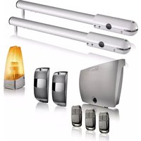
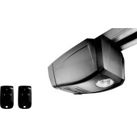
Product description
Pack contents

text_image
Diagram illustrating the assembly of a battery pack with labeled components and directional arrows indicating flow or movement.| ID Designation Qty | |
| a Motor x 1 | |
| b Rack section33 cm x 20 mm* | x 12 |
| c Installation template x 1 | |
| d 2-button remote control** | |
| e Set of photoelectric cells* x 1 | |
| f Flashing light* x 1 | |
| g Installation andoperating manual | x 1 |
*depending on the pack chosen
| ID Designation Qty | ||
| h Earth wire x 1 | ||
| i Self-drilling screw x 4 | ||
| j Cable clamp x 1 | ||
| k Stud | x 4 | |
| l Plug | x 4 | |
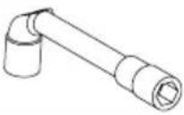
| m | Somfy pencil | x 1 |
| n Cover screw | x 1 | |
| o O-ring | x 1 | |
| p Insulated round terminal | x 1 | |
| q Small flat washer | x 2 | |
| r Toothed lock washer | x 2 | |
| s Flat washer | x 8 | |
| t Nut | x 8 | |
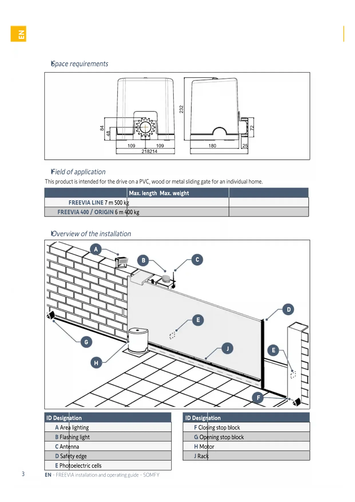
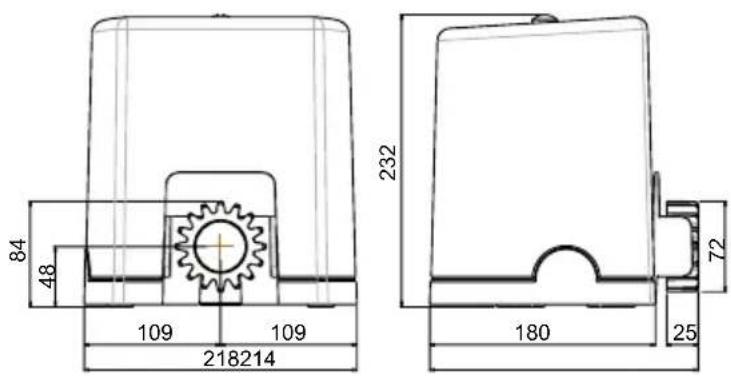
Space requirements
text_image
84 48 109 109 218214 232 180 72 25Field of application
This product is intended for the drive on a PVC, wood or metal sliding gate for an individual home.
| Max. length Max. weight | ||
| FREEVIA LINE 7 m 500 kg | ||
| FREEVIA 400 / ORIGIN 6 m 400 kg | ||
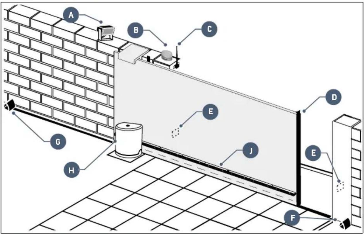
Overview of the installation
text_image
Diagram of a wall-mounted electrical or mechanical assembly with labeled components A through J, showing connections and structural details.| ID Designation |
| A Area lighting |
| B Flashing light |
| C Antenna |
| D Safety edge |
| E Photoelectric cells |
| ID Designation |
| F Closing stop block |
| G Opening stop block |
| H Motor |
| J Rack |
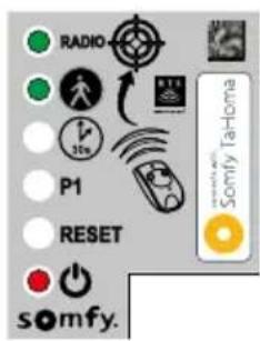
Control electronics description
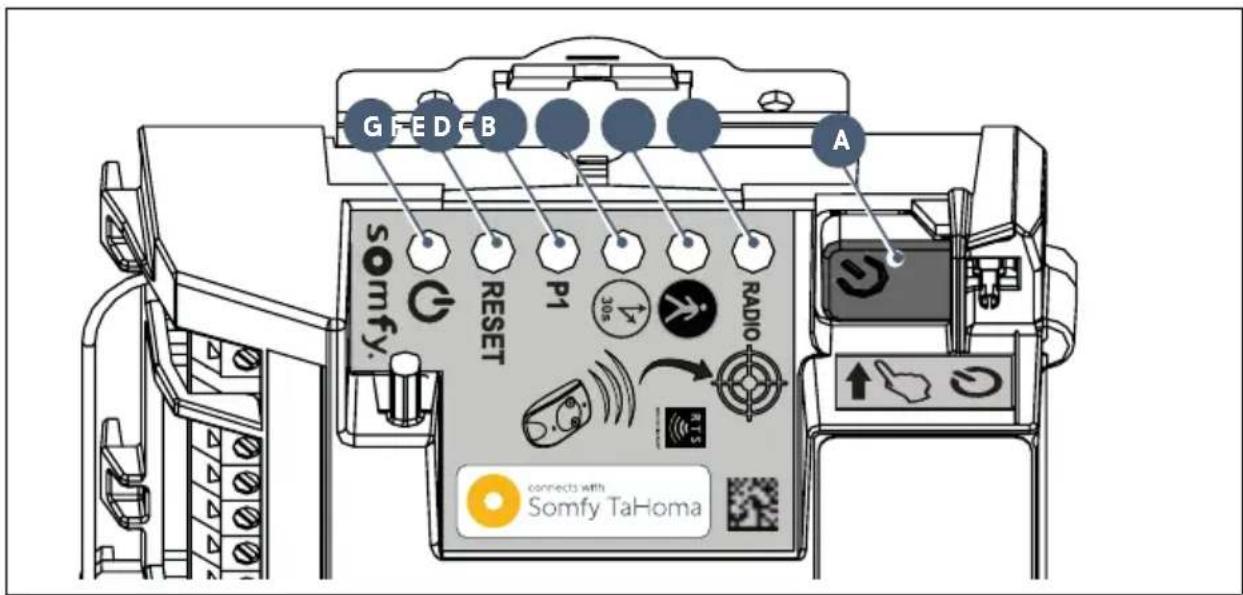
text_image
G F E D B A somfy. RESET P1 30s RADIO connects with Somfy TaHoma| ID Designation Function | |||
| A |  | Start auto-programmingReactivate the control electronics | |
| B RADIO indicator light | Comes on each time the control electronics receive a radio command | ||
| C |  or light or light | On upon activation/deactivation of pedestrian opening | |
| Flashes slowly photoelectric cells present and recognised | |||
| Flashes quickly indicates a fault on the photoelectric cells, see page 32 | |||
| D |  or light or light | On automatic gate closing is activated | |
| OFF automatic gate closing is deactivated | |||
| Flashes quickly the "automatic closing" parameter is selected | |||
| E |  or light or light | OFF | the gate operates at standard speed |
| Flashes slowly the gate operates at slow speed | |||
| Flashes quickly the gate "speed" parameter is selected | |||
| F RESET indicator light | On the settings alone or the settings and the radio control points are deleted | ||
| Flashes quickly the settings and radio control points deletion function is selected | |||
| G |  or light or light | On the motor functions correctly - the control electronics are reactivated | |
| OFF the motor functions correctly - the control electronics are on standby | |||
| Flashes see diagnostic on page 32 | |||
Prerequisites for installation
Ground stop blocks (not supplied)
The gate travel must be defined by stop black anchored firmly in the ground.
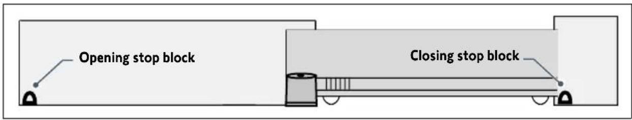
text_image
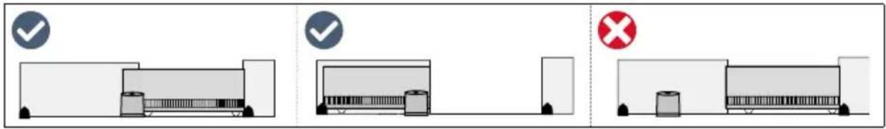
Opening stop block Closing stop blockPositioning the motor
text_image
Diagram showing three scenarios of building inspection with checkmarks and a red X mark, likely indicating failure or invalid status.Electrical pre-equipment
Cables required
- Mains power supply: 3 x 1.5 mm ^2 cable or 3 x 2.5 mm ^2 for outdoor use (at least H07RN-F)
• Cell connections: 2 x 0.75 mm² cable
• Other accessories: see page 6

The power supply cable run must be set up in accordance with the electrical standards in force in the country of use.
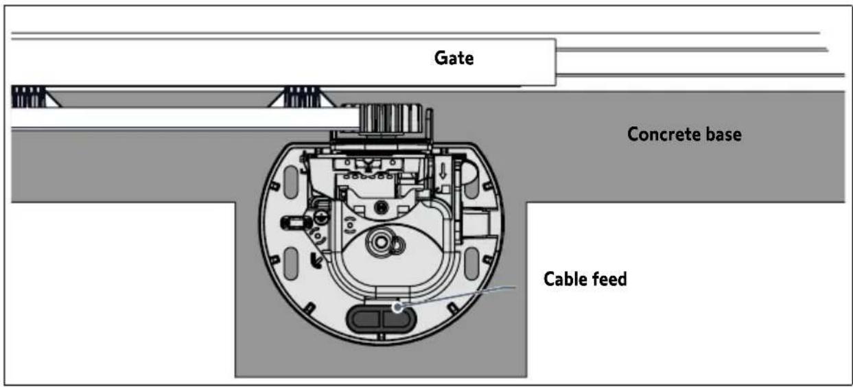
Cable feed
• Underground cables must be equipped with a protective sheath with a sufficient diameter to contain all the cables.
- Fit a 230V electrical input as close as possible to the motor.

If a cable trench cannot be dug, use a cable grommet which can withstand the weight of passing vehicles (ref. 2400484).
text_image
Gate Concrete base Cable feedCables required

The wiring details are provided in the "ACCESSORIES WIRING" section on pages 18 to 21.
text_image
TX RX Coaxial cable 2 x 0.75 mm² 2 x 0.75 mm² 2 x 0.75 mm² 2 x 0.75 mm² 2 x 0.75 mm² 2 x 0.75 mm² 500 W max. 3 x 1.5 mm² 230V mains power supply 3 x 1.5 mm² or 3 x 2.5 mm² for outdoor use (at least H07RN-F) ANT 1 2 BUS 3 4 BUT 5 6 24V 7 8 9 FLASH M1 11 M2 12 13 BATT 10+10 + LIGHT 14 15 230V 16 17
To connect several accessories to the START terminal, a wire with a 0.3 mm^2 cross-section may be used (example: telephone cable) instead of a wire with a 0.75 mm^2 cross-section.
Concrete base

The concrete base on which the motor will be installed must comply with the dimensions indicated in the diagram below.
text_image
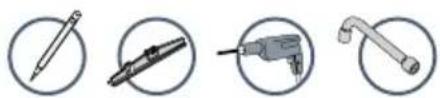
Gate Base -150 mm Cable feed Deck Crema Ilère Gate Base 250 mm mini 36 200 mm miniTools required for installation (not supplied)

text_image
17 3,5 T25 PZ2 10 12Fasteners required for rack installation (not supplied)
This information is provided for guidance purposes.
| Fasteners required Tools required Drilling diameter | |||
| IRON OR ALUMINIUM GATE | Self-drilling hex-head screw for metal, type ST 6.3 x 30 mm + washer | No.10 socket spanner | 5 mm with a drill for steel |
 |  | ||
| PVC GATE | PVC is too fragile to fasten the rack directly.PVC gates generally have an aluminium or metal brace or a steel core(see the line above).If a PVC gate does not have a brace: fasten a metallic brace to the gate, at the rack fastening point. | ||
| WOODEN GATE | Wood screws, diameter 6 x 40 mm minimum + washer | No.10 socket spanner | Make a starter hole with a wood drill, diameter 2.5 mm, or a wood auger. |
 |  | ||
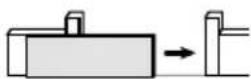
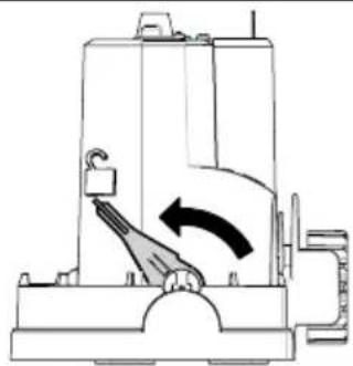
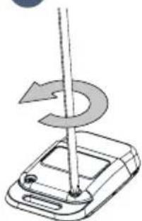
1.1 Unlocking the motor
natural_image
Technical line drawing of a mechanical device with an arrow indicating rotation or movement (no text or symbols present)Position the motor handle

The pinion is released.
The motor is unlocked.
1.2 Installing the motor
- Anchoring the motor in the grou

text_image
Collection of nine different tools and components, each labeled with a number from 12 to 25.1
natural_image
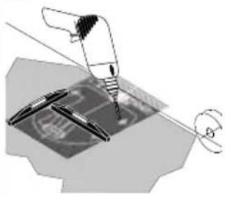
Mechanical assembly diagram showing a turning tool interacting with a component (no text or symbols visible)- Position the installation template ⓒ on the ground, and drill 4 holes using a drill bit (∅ 12 mm) suitable for the type of ground.
2
natural_image
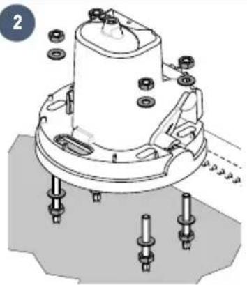
Technical diagram of a mechanical assembly with bolts and a central component (no text or symbols)- Insert the plugs. Screw in the studs.
- Screw on 4 nuts with 4 washers.
- Remove the motor cover.
- Position the motor on the studs: ensure that the
bracket (motor base) is no more than 25 mm above the ground. The recommended space is between 20 and 25 mm.
- Once the motor is positioned at the right height in relation to the ground, fasten it using 4 washers and 4 nuts.

text_image
20 mm ^3
natural_image
Technical line drawing of a mechanical component with a curved base and mounting holes (no text or symbols)- Position the pre-drilled grommet in the opening provided for the cable feed.

Check that the motor is level.
Fastening the rack

natural_image
Four circular icons showing different types of tools: pen, tool, drill bit, and wrench (no text or symbols)!
- The rack must be fastened to the gate brace.
- Use screws suitable for your gate's material (see page 8).
- Never lubricate the motor rack or pinion.
i
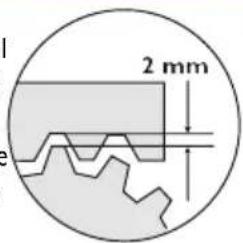
- Align the top of the rack with the pencil mark, to ensure the 2 mm gap required between the rack and the pinion.
- If the fastening points are too close to the edge of the brace: fasten the rack to the centre of the oblong holes.
text_image
2 mm1
text_image
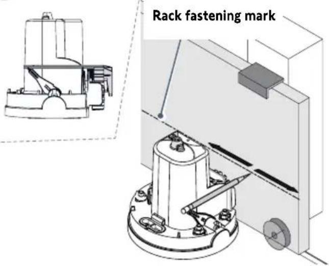
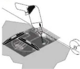
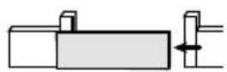
Rack fastening mark- Open the gate fully.
- Place the pencil supplied on the notches provided on the motor.
- Hold the pencil in one hand, and with the other slide the gate to mark the position of the rack.
2
natural_image
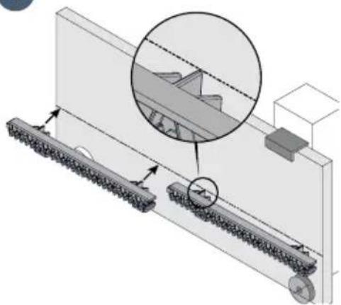
Technical diagram of a mechanical assembly with rollers and a gear mechanism, showing alignment and assembly details (no text or symbols)- Place the rack by aligning the top of the rack with the pencil mark.
- Fasten the first rack component on the top of the oblong holes, stating on the motor side.
- Fit and fasten the other components in the same way, slotting them into each other.
1.3 Checking the motor installation
Check that:
• the motor is level.
• the gate runs correctly.
• the pinion is correctly driven.
- the 2 mm gap between the rack and pinion does not vary excessively.
If these conditions are not satisfied, adjust the rack height.
Once all these checks have been completed, tighten the nuts to fasten the motor permanently.
1.4 Locking the motor

Never lock the motor when the gate is moving, as this could damage the drive.

natural_image
Diagram of a mechanical device with an arrow indicating rotational motion (no text or symbols)Push the motor handle towards the gate.
The motor is locked.
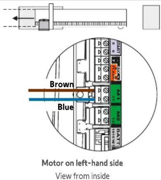
1.5 Wiring the motor


For your safety, these operations must be carried out with the power off.

By default, the motor is wired for installation on the left of the gate.
To install the motor on the right of the gate, switch the wires connected to terminals 10 and 11 of the control electronics (green M1 label).
text_image
Brown Blue Motor on left-hand side View from inside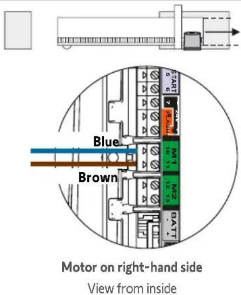
text_image
Blue Brown Motor on right-hand side View from inside
Do not connect anything to terminal M2.
1.6 Connecting to the 230V mains power supply

natural_image
Four circular icons showing different types of tools: screwdriver, pliers, screwdriver with cross symbol, and a circle with a minus sign (no text or labels)
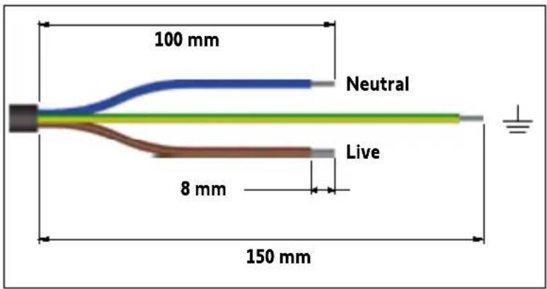
- For your safety, these operations must be carried out with the power off.
- Use a 3 x 1.5 mm ^2 or 3 x 2.5 mm ^2 cable for outdoor use (at least H07RN-F).
-
The cable clamp supplied must be used.
For all low-voltage cables, ensure that they can withstand a 100 N pull force.
Check that the conductors have not moved after applying this pull force. -
Strip the wire over 150 mm.
- Trim the live and neutral wires at 100 mm.
- Strip the 3 wires over 8 mm.
- Crimp the terminal provided on the earth wire (yellow and green).
- Connect the wires as shown in the table:
text_image
100 mm Neutral Live 8 mm 150 mm| Wire colour Type Terminal | Comments | ||
| Blue Neutral 17 | |||
| Brown / black / red | Live 16 | ||
| Yellow and green | Earth |  | Fit a flat washer q the power supply earth terminal crimped in step 4 and a toothed lock washer using a screw i |

text_image
Live 16 230V 17 Neutral A7. Tighten the cable clamp supplied.
natural_image
Technical line drawing of a mechanical assembly with no visible text or symbolsFor a 3x1.5 mm ^2 cable For a 3x2.5 mm ^2 cable
1.7 Earthing the control electronics
- Connect the earth wire supplied h the top right of the control electronics.
- Fit a flat washer q, the earth wire terminal h and a toothed lock washer ring a screw i on the top of the motor.
natural_image
Technical diagram of a mechanical assembly with labeled parts and a magnified inset showing internal components (no readable text or symbols)1.8 Position of the control electronics antenna
Position the antenna on top of the motor.

natural_image
Technical line drawing of a mechanical device with no visible text or symbols2.1 Powering on the installation
- The ⏻ indicator flashes (twice).
The motor is switched on and awaiting auto-programming.
- If the indicator light does not come on or the number of flashes is not as expected: see diagnostic on page 32.
2.2 Gate travel auto-programming
Prerequisite - before starting auto-programming, check that:
- The installation is powered on: the Indicator light flashes (twice).
- The gate is at its mid-point. - The motor is locked.
text_image
S R B E S R S R S R S R S R S R S S S S S S S S S S S S S S S S S S S S S S S S S S S S S S S S S S S S S S S S S S S S S S S S S S N O P M A B C D E F G H I J K L M N O P Q R S


Press the button on the control electronics.
- The gate opens, closes, opens partially and closes again.
• The Ⓧ indicator light is lit continuously.
Auto-programming has been successfully completed and the motor is operational.

If the ⏻ indicator light flashes (twice), begin auto-programming again.
The gate must be closed once auto-programming is complete.

If the gate is open, see the IMPORTANT box below.

IMPORTANT
If the gate is open once auto-programming is complete:
- Clear the settings (see page 31).
- Power the motor off.
- Switch the wires connected to terminals 10 and 11 (green M1 label) of the control electronics (see "Motor wiring", page 12).
- Unlock the motor.
- Position the gate at its mid-point.
- Lock the motor.
- Power the motor on.
- Begin auto-programming again.

During the auto-programming process, pressing button 1 on the remote control or the button on the control electronics causes the gate and the auto-programming process to stop.
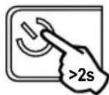
2.3 Control electronics standby / reactivation
i
Once the auto-programming process has been completed, the electronics automatically switch to standby after 5 minutes of inactivity to save energy. In standby mode, all the indicator lights are off.
To check whether the motor is powered on or to check/modify the parameter setting, press the button for 2 seconds to activate the electronics.
2.4 Plugging the openings

i
You are strongly advised to plug all the openings to prevent short circuits caused by insects.
Once all the cables have been fed through, plug the openings (oblong holes, cable feed openings) using silicone.
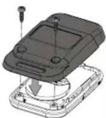
2.5 Fitting the cover
text_image
Technical diagram of a mechanical component with labeled parts and directional arrows indicating assembly or assembly steps.
text_image
Technical diagram of a mechanical component with labeled parts and directional arrows indicating assembly or assembly steps.- Place the cover on the motor.
- Insert the seal to insure the motor and cover screw in the watertight.
- Screw down the cover.
2.6 Fully opening and closing the gate
i
The remote controls supplied with the kit are already memorised and programmed so that button 1 on the remote controls requests full opening of the gate.
Button 1
natural_image
Illustration of a gray remote control device with wireless signal waves and a 'somy' logo (no text or symbols on the device itself)
text_image
STOP- Gate closed: press button 1 on the remote control to open the gate fully.
- Gate moving: press button 1 on the remote control to stop the gate.
- Gate open: press button 1 on the remote control to close the gate.
2.7 Obstacle detection
If an obstacle is detected (abnormal force on the drive):
- When the gate is opening: the gate will stop.
- When the gate is closing: the gate will stop and reopen.

For your safety, these operations must be carried out with the power off.

You are advised to perform gate travel auto-programming before connecting the accessories (photoelectric cells, flashing light, etc.)
3.1 Photoelectric cells

text_image
TX RX 1 2 1 2 3 5 BUS 3 4or
text_image
TX RX 1 2 1 2 BUS 3 4C S
Installation
After wiring the cells, and to check that the cells are properly aligned:
- Power the motor back on again.
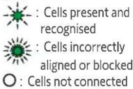
- Press the button on the control electronics for 2 seconds to activate the electronics and power the cells. The indicator light on the RX receiver cell should light up when the cells are correctly aligned.
Cell recognition by the motor electronics in normal operating mode

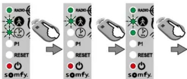
This procedure below can only be applied in the following cases:
- Connecting photoelectric cells after auto-programming has been completed.
- Removing photoelectric cells in normal operating mode (in automatic closing mode, the photoelectric cells are mandatory).
- Deactivating the operating mode with automatic closing.


text_image
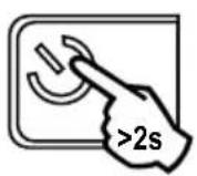
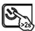
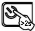
>2s RADIO P1 RESET somfy.- Press the button on the control electronics for 2 seconds.
The indicator light comes on. - Place the remote control against the control electronics.
Press and hold button 1 on the remote control until the indicator light flashes.
flowchart
graph TD
    A["->2s"] --> B["→"]
    B --> C["✓"]
    A --> D["→"]
    D --> E["/ ○"]
    E --> F["×"]
- Press the Button on the control electronics for 2 seconds.
The indicator light indicates the status of the cells:
text_image
: Cells present and recognised : Cells incorrectly aligned or blocked ○ : Cells not connected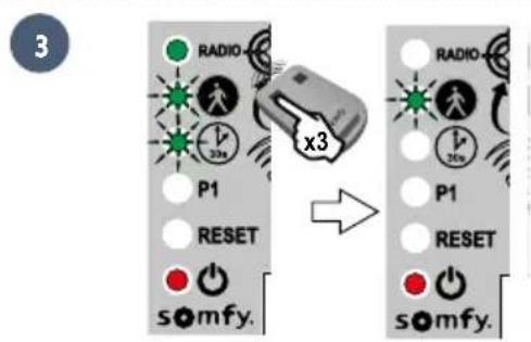
text_image
3 RADIO x3 P1 RESET s\u2086mfy. RADIO x3 P1 RESET s\u2086mfy.- Press button 1 on the remote control 3 times.
▶Operation with photoelectric cells
If the cells are blocked when closing the gate, the gate will stop and reopen.
If the gate is open and the cells are blocked, the gate will not close.
In the event of photoelectric cell removal
If cells have been removed, repeat the cell recognition procedure by the motor electronics
3.2 Flashing light

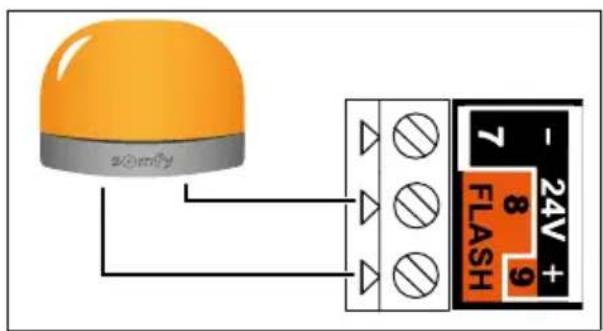
text_image
zomfy 7 24V + 8 9 FLASH
10 W - 24V bulb MAXIMUM - Using a bulb with power greater than 10 W - 24V can cause drive malfunctions.
Flashing light operation
The light flashes while the gate is moving.
3.3 battery

This accessory is not compatible with solar power.
i
To ensure an optimum battery life, switch the gate's electric power supply off at least 3 times a year to run a number of cycles using the battery.

natural_image
Technical line drawing of a mechanical assembly with cylindrical components and internal components (no visible text or symbols)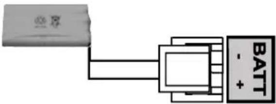
text_image
BATT - +Battery specifications:
- Battery life: 10 continuous cycles or 24 hours on a gate in perfect condition.
- Optimum charging time before using the battery: 48 hours.
• Service life: 3 years.
The backup battery ensures the operation of the gate in the event of an electrical power failure. The ⏻ indicator light flashes (once) when the motor is operating on the battery.
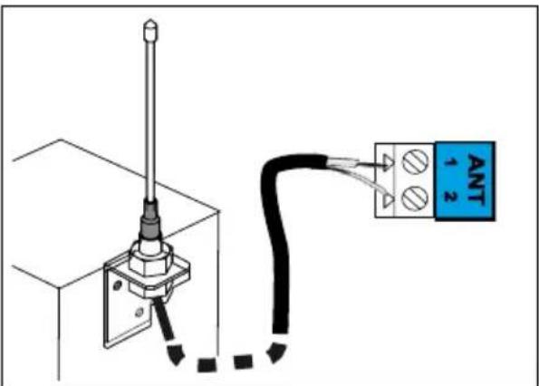
3.4 Remote antenna
text_image
ANT -1 2i
The wire antenna can be replaced with a longer-range remote antenna.
This is placed on top of the pillar and must be clearly accessible.
The offset antenna is connected to terminals 1 and 2 of the electronics unit (blue "ANT" label):
• the wire core to terminal 1
• the ground strap to terminal 2
text_image
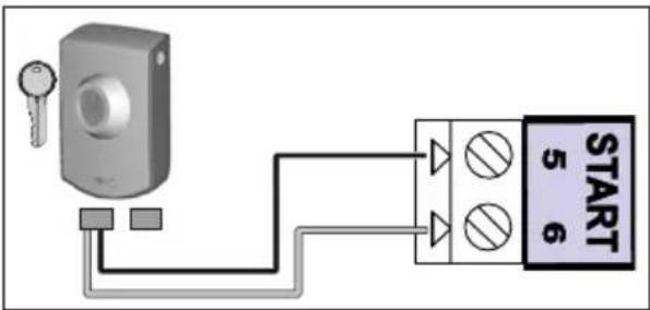
Only connect one non-powered dry contact.3.6 Key contact

text_image
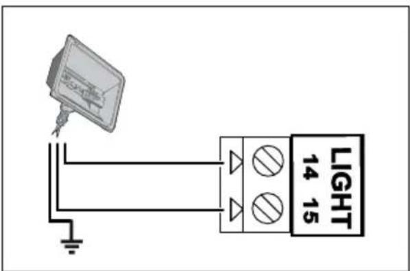
START 5 63.7 Area lighting

text_image
LIGHT 14 15▶ Lighting output power
The maximum lighting output power is 500 W:
• either 5 fluocompact or LED lights
• or 2 power supplies for low-voltage LEDs
• or 1 halogen light, max. 500 W
▶ Area lighting operation
Area lighting comes on each time the drive is started up. It goes out automatically 1 minute and 30 seconds after movement has finished.
3.8 Solar power

Never connect the motor to a 230V power supply when it is connected to a solar power supply, as this could damage the motor's electronics unit.

text_image
BATT - +4.1 Pedestrian opening
▶ Pedestrian opening operation

text_image
1m
natural_image
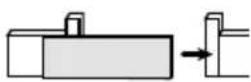
Diagram showing a hand interacting with a rectangular block and a separate block, with an arrow indicating motion (no text or symbols present)Pressing the remote control button programmed to open the pedestrian opening causes the gate to open about 1 metre. Pressing the button again re-closes the gate.
▶ Activating pedestrian opening
i
Button 1 on 2- or 4-button remote controls cannot be programmed to control the gate's pedestrian opening. See "Programming the remote controls", on pages 27-29, for more information.
12
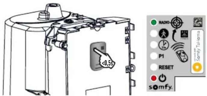
- Press the button on the control electronics for 2 seconds. The Indicator light comes on.

text_image
<0,5 s- Place the remote control against the control electronics.
text_image
RADIO P1 RESET somfy. Somfy TaHoma- Press button 2 on the remote control.
The "RADIO" and 🎨 indicator lights come on then go out. The pedestrian opening is activated on this button.
i
Move away from the control electronics to test pedestrian opening.
▶ Deactivating pedestrian opening
Repeat the "Activate pedestrian opening" procedure using the button for which pedestrian opening must be deactivated. The indicator light comes on then goes out. The pedestrian opening is deactivated for this button.
4.2 Automatic closing
▶ Automatic closing operation
Press button 1 on the remote control to open the gate.
The gate closes again after 30 seconds, or 5 seconds if the photoelectric cells detect a passage motion.
Automatic closing can be interrupted by pressing button 1 on the remote control. To reclose the gate, press button 1 on the remote control again.
▶ Activating automatic closing

Automatic closing can only be activated if the photoelectric cells are connected and recognised by the motor's control electronics.
12
- Press the button on the control electronics for 2 seconds. The Indicator light comes on.

text_image
RADIO P1 RESET somfy. Somfy TaHoma- Place the remote control against the control electronics.
- Press and hold button 1 on the remote control until the indicator light flashes quickly.
45
flowchart
graph LR
    A["Start"] --> B["P1"]
    B --> C["RESET"]
    C --> D["somfy."]
    D --> E["Next Step"]
    E --> F["P1"]
    F --> G["RESET"]
    G --> H["somfy."]
    H --> I["Next Step"]
    I --> J["RADIO"]
    J --> K["30s"]
    K --> L["Radio"]
    L --> M["30s"]
    M --> N["P1"]
    N --> O["RESET"]
    O --> P["somfy."]
- Press and hold button 2 on the remote control until the indicator light goes out and then is lit continuously.
text_image
RADIO P1 RESET somyf. x3 RADIO P1 RESET somyf.- When you release button 2, the indicator light flashes; press button 1 on the remote control 3 times
The indicator light remains on. Automatic closing is activated.
▶ Deactivating automatic closing
12
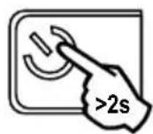
- Press the button on the control electronics for 2 seconds. The Indicator light comes on.

natural_image
Technical line drawing of a mechanical device with no visible text or symbols- Place the remote control against the control electronics.

text_image
RADIO P1 RESET somfy. Somfy Tailoma- Press and hold button 1 on the remote control until the indicator light flashes.
4
text_image
RADIO 30% P1 RESET somfy.
- Press button 2 on the remote control. The indicator light goes out then flashes.
5
6

- Press button 1 on the remote control 3 times.
The indicator light is off. Automatic closing is deactivated.
i
4.3 Gate speed
By default, the gate operates at standard speed.

DANGER Any change to the gate speed setting must be performed by a professional drive and home automation installer. Any changes which do not comply with these instructions represent a danger to the safety of both people and property.
▶ Field of application
Set the gate speed in accordance with the table below:
| Gate weight Standard speed Slow speed | ||
| 0 to <100 kg |  |  |
| 100 to <200 kg |  |  |
| 200 to <300 kg | [TA40] + safety edge* |  |
| 300 to <400 kg |  + safety edge* + safety edge* | [YOHT] |
| 400 to 500 kg |  | [5607]  |
*A passive safety edge (ref. 9019612) must be installed on the gate.

WARNING If the speed setting is changed, the installer must check that the obstacle detection system complies with Annex A of standard EN 12 453. Failure to follow these instructions could result in serious injury, e.g. crushing by the gate.
▶ Setting slow speed

text_image
12 • Press the button on the control electronics for 2 seconds. The Indicator light comes on. • Place the remote control against the control electronics. • Press and hold button 1 on the remote control until the indicator light flashes. • Press button 1 on the remote control once. • The P1 indicator light flashes quickly.▶ Setting slow speed (continued)

flowchart
graph LR
    A["Start"] --> B["Signal State P1"]
    B --> C{Reset}
    C --> D["Radio buttons: P1, somfy."]
    D --> E["Result"]
    E --> F["Signal State P1"]
    F --> G{Reset}
    G --> H["Radio buttons: P1, somfy."]
- Press and hold button 2 until the P1 indicator light flashes slowly. Slow speed is selected.
text_image
7 RADIO P1 RESET x2 RADIO P1 RESET somfy. somfy.- Press button 1 on the remote control twice. The P1 indicator light flashes slowly. Slow speed is selected.
▶ Returning to standard speed
1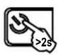 | 2 | 3 |
| • Press the button on the control electronics for 2 seconds.The Indicator light comes on. | • Place the remote control against the control electronics. | • Press and hold button 1 on the remote control until the indicator light flashes. |
4 | 5 | 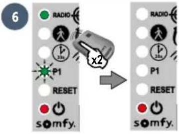 |
| • Press button 1 on the remote control once.The P1 indicator light flashes. | • Press button 2 on the remote control once.The P1 indicator light goes out for 5 seconds then flashes quickly. | • Press button 1 on the remote control twice. The P1 indicator light is off.Standard speed is selected. |
5.1 Remote controls description
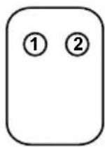
2-button remote control
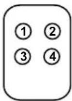
4-button remote control
Depending on the parameter setting options, Somfy RTS remote controls can control:
• full opening of the gate
• pedestrian opening of the gate
- another Somfy RTS device (e.g.: garage door motor, roller shutter, etc.)
i
The remote controls supplied with the kit are already memorised and programmed so that button 1 on the remote controls requests full opening of the gate.
i
You can memorise up to 16 control points for a motor (remote controls, other radio control points). If you memorise a 17th control point, the first point memorised will automatically be deleted.
i
If you wish to program a pedestrian opening, it must be programmed on the button following the one used to open the gate fully (e.g.: full opening controlled by button 2, pedestrian opening controlled by button 3). It is not possible to programme pedestrian opening on button 1 of the remote controls.
▶ 2-button remote control programming options
| Button 1 | Button 2 | |
| Option 1 Full opening Pedestrian opening or other | Somfy RTS automated system | |
| Option 2 Another Somfy RTS device Full opening | ||
▶ 4-button remote control programming options
| Button 1 | Button 2 | Button 3 | Button 4 | |
| Option 1 Full opening Pedestrian opening | or other Somfy RTS automated system | Other Somfy RTS automated system | Other Somfy RTS automated system | |
| Option 2 Other Somfy RTS automated system | Full opening Pedestrian | opening or other Somfy RTS automated system | Other Somfy RTS automated system | |
| Option 3 Other Somfy RTS automated system | Other Somfy RTS automated system | Full opening Pedestrian | opening or other Somfy RTS automated system | |
| Option 4 Other Somfy RTS automated system | Other Somfy RTS automated system | Other Somfy RTS automated system | Full opening | |
▶ Using a 3-button remote control

text_image
Open Stop Close- To open the gate fully, press the "Up" button on the remote control.
- To stop the gate while it is moving, press the central button on the remote control.
- To close the gate, press the "Down" button on the remote control.
i
The 3-button remote control cannot be used to change the motor parameter settings.
5.2 Adding a remote control
▶ 2- or 4-button remote control
12

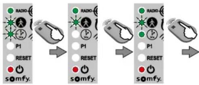
- Press the button on the control electronics for 2 seconds. The Indicator light comes on.

text_image
<0,5s RADIO 32V P1 RESET somfy.- Place the new remote control to be programmed against the control electronics.
- Press and release the button on the remote control to be programmed. The "RADIO" indicator light will come on and then go out when you release the button on the remote control. Full opening is programmed on this button.
▶ 3-button remote control
12
- Press the button on the control electronics for 2 seconds. The indicator light comes on.


text_image
<0,5s RADIO P1 RESET somfy.- Place the remote control against the control electronics.
- Press and release a button on the remote control to be programmed. The "RADIO" indicator light will come on and then go out when you release the button on the remote control. The remote control has been memorised.
5.3 Deleting remote controls
See "Clearing the settings" page 31.

The drive must be disconnected from any power supply source during cleaning and maintenance, or when replacing parts.
6.1 Assistance
Despite the care taken in the design of our products and the creation of our guides, you may encounter difficulties during the installation of your automatic control device or have some unanswered questions. Do not hesitate to contact us; our specialists are on hand to answer all your questions.
6.2 Replacing the remote control battery
The service life of the battery is generally 2 years.
12
natural_image
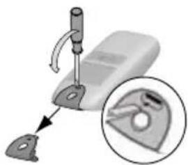
Mechanical device with a tool and magnified inset showing a close-up of a mechanical part (no text or symbols visible)- Remove the remote control clip.

natural_image
3D illustration of a device with a curved panel and two arrows indicating motion or force (no text or symbols)- Insert the screwdriver in the slot and lift the cover.

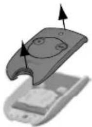
natural_image
Illustration of a computer mouse with a plus button and a small inset showing a battery (no text or symbols)- Remove the battery using a screwdriver.

natural_image
Close-up of a computer mouse with a cursor pointing to the internal panel (no text or symbols visible)- Replace the battery (3 V CR 2430 or CR 2032).
12

natural_image
Diagram of a mechanical device with a rotating shaft and curved arrow indicating rotation (no text or symbols)• Unscrew the rear of the remote control.

- Remove the screws.


natural_image
Diagram showing a device being placed into a closed housing, with an arrow indicating the process (no text or symbols present)- Remove the rear of the remote control.

natural_image
Diagram of a smartphone showing internal components and a circular button with an 'X' symbol (no text or labels present)- Replace the battery (3V CR 2430 / CR 2032).


natural_image
3D mechanical assembly diagram showing a device with mounting holes and internal components (no text or symbols)• Refit and screw on the rear of the remote control.
6.3 Clearing the settings
When should I clear the settings?
- After auto-programming, if you change the position stop block, if you change the motor wiring or if you add a safety edge to the gate.
- If the gate keeps opening haphazardly due to normal wear of the gate.
 Press the button on the control electronics for 2 seconds. The indicator light comes on. Press the button on the control electronics for 2 seconds. The indicator light comes on. | 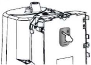 Place the memorised remote control against the control electronics Place the memorised remote control against the control electronics | 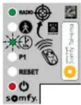 Press and hold button 1 on the remote control until the indicator light flashes quickly. Press and hold button 1 on the remote control until the indicator light flashes quickly. |  Press button 1 on the remote control twice. Press button 1 on the remote control twice. |  The “RESET” indicator light flashes quickly. The “RESET” indicator light flashes quickly. |
To clear the settings* 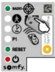 | To clear the settings* and the memorised remote controls/control points 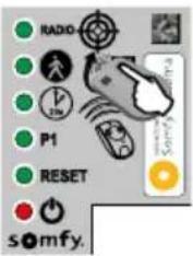 | |||
 |  | The Indicator light flashes twice (see page 15 to run an auto-programming procedure). | ||
*Gate travel, deactivating the parameters, etc.
6.4 Diagnostics
i
The electronics automatically switch to standby after 5 minutes of inactivity, to save energy. In standby mode, all the indicator lights are off.
To run a diagnostic on your drive, press and hold 🤕 for 2 seconds to reactivate the electronics and observe the status of the indicator lights.
Diagnostics Troubleshooting
| The motor does not respond to commands from the remote control | The remote control range is reduced | ·Check the remote control battery ("Replacing the remote control battery", see page 30). ·Check the antenna on the electronics unit (wiring, position, see page 14). ·Check that there are no external factors that may be interfering with the radio transmission (electric pylon, metal reinforced walls, etc.). If this is the case, fit a remote antenna. |
| Non-memorised remote control | Memorise the remote control (see page 29). | |
| Motor unlocked Lock the motor. | ||
| The indicator light flashes quickly Photoelectric cells blocked. | Check that there are no obstacles between the cells. | |
| The indicator light on the electronics unit is off | The electronics unit is on standby | Press for 2 seconds to reactivate the electronics unit. |
| No power supply to the control electronics | ·Check the mains power supply. ·Check the power supply cable. | |
| The indicator light on the electronics unit is flashing: | ||
| 1 flash Operating | on backup battery Check the mains power supply. | |
| 2 flashes Motor waiting for gate travel to be programmed | Start auto-programming (see page 15). | |
| 4 flashes Short-circuit on electronic unit "START" (terminals 5-6) | Check the accessories connected to the electronic unit's "START" output. | |
| 5 flashes Motor thermal protection device activated | Allow the motor to cool down for several minutes. | |
| 6 flashes Short-circuit on the electronics unit's "BUS" (terminals 3-4) | Check the accessories connected to the electronic unit's "BUS". | |
| Short-circuit on the electronics unit's "24 V" (terminals 7-9) | ||
| Short-circuit on the electronics unit's "flashing light" (terminals 8-9) | ||
| Motor short-circuit Check the motor wiring (see page 12). | ||
| 7 flashes Electronic fault Contact Somfy assistance | ||
| Automatic closing mode is not activated (the indicator light stays off). | The indicator light is off. Photoelectric cells not installed | Install cells (see guide supplied with the cells for installation, and page 18 for wiring). |
| The indicator light flashes quickly. Photoelectric cells not aligned or blocked. | Check that there are no obstacles between the cells. Check cell alignment. | |
6.5 Opening the motor memory
To facilitate adding coded keypad or TaHoma radio controls, you can open the motor electronics memory in order to memorise your equipment remotely.

The motor memory can only be opened if auto-programming has already been run.
1
- Press the button on the control electronics for 2 seconds. The indicator light comes on.
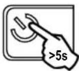
- Press the 🎨 button on the control electronics for 5 seconds. The "RADIO" indicator light comes on. The memory is open. Program the control as per the instructions supplied with it.
| Power supply 230 V-50 Hz / 24V (with solar power) | |
| Motor type 24V | |
| Motor power 120 W | |
| Max. power consumed (with area lighting) | 600 W |
| Standby consumption 0.21 W | |
| Maximum manoeuvre frequency per day 20 cycles / day | 10 cycles / day on solar power |
| Opening time 16 s for a 150 kg/3m gate | |
| Automatic obstacle detection Compliant with standard | EN 12 453 |
| Operating temperature -20°C to +60°C | |
| Thermal protection Yes | |
| Index protection rating IP 44 | |
| Insulation Category 1 | |
| Built-in radio receiver Yes | |
| Remote controls | |
| • Radio frequency 433.42 MHz, < 10 mW | |
| • Range in field of use | ~30 m |
| • Storage quantity | 16 |
| Possible connections: | |
| • Flashing light output | Flashing, 24V, 10 W maximum |
| • Lighting output | 500 W max at 230V either 5 fluocompact or LED lights or 2 power supplies for low-voltage LEDs or 1 halogen light, max. 500 W |
| • Accessories power supply output | 24VDC / 15 W max. |
| • Backup battery input | Yes |
| • Photoelectric cell input | Yes (up to 2 sets of photoelectric cells) |
| • Dry contact control input | Yes |
Inhaltsverzeichnis
text_image
Diagram illustrating the assembly of a battery pack with labeled components and directional arrows indicating flow or movement.text_image
Diagram of a wall-mounted electrical or mechanical assembly with labeled components A through J, including a brick wall and panel.text_image
G F E D B A somfy. RESET P1 30s RADIO connects with Somfy TaHomatext_image
Diagram showing three scenarios of building inspection with checkmarks and a red X mark, likely indicating failure or invalid status.natural_image
Technical line drawing of a mechanical device with an arrow indicating rotation or movement (no text or symbols present)text_image
Row of tool icons with labels and numbers, showing various mechanical and electrical components1
natural_image
Diagram of a precision tool interacting with a mechanical component (no text or symbols visible)- Legen Sie die
natural_image
Technical diagram of a mechanical assembly with bolts and a central component (no visible text or symbols)natural_image
Diagram of a curved mechanical component with a directional arrow indicating motion (no text or symbols)- Bringen Sie die
vorgebohrte
natural_image
Four circular icons showing different types of tools: pen, screwdriver, drill bit, and wrench (no text or symbols)!
natural_image
Technical diagram of a mechanical assembly with rollers and a housing, showing alignment and component details (no text or symbols)natural_image
Diagram of a mechanical device with an arrow indicating rotational motion (no text or symbols)natural_image
Four tool icons in circular frames: screwdriver, pliers, wrench, and cross (no text or symbols)
natural_image
Technical line drawing of a mechanical assembly with no visible text or symbolsnatural_image
Technical diagram of a mechanical assembly with two circular insets showing internal components (no text or labels)natural_image
Technical line drawing of a mechanical device with no visible text or symbolstext_image
Sarry Talkama


text_image
Technical diagram of a mechanical component with labeled parts and directional arrows indicating assembly or assembly steps.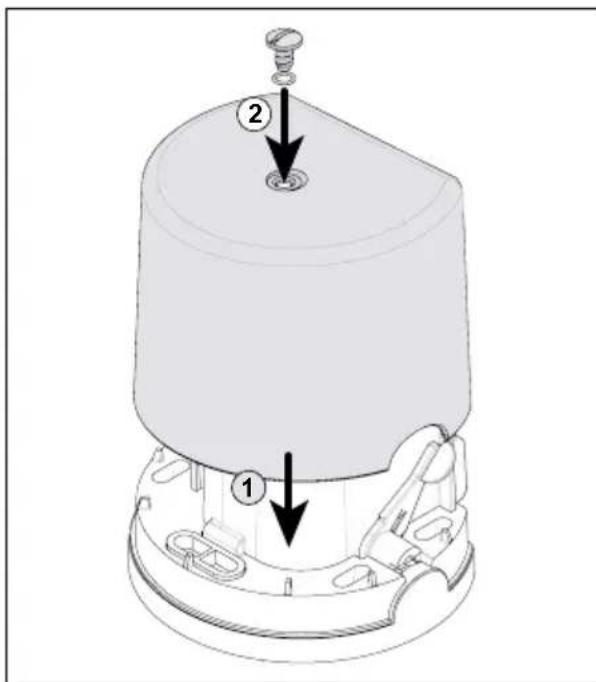
text_image
Technical diagram of a mechanical component with labeled parts and directional arrows indicating assembly or assembly steps.natural_image
Illustration of a gray remote control device with wireless signal waves and a black square button (no text or symbols)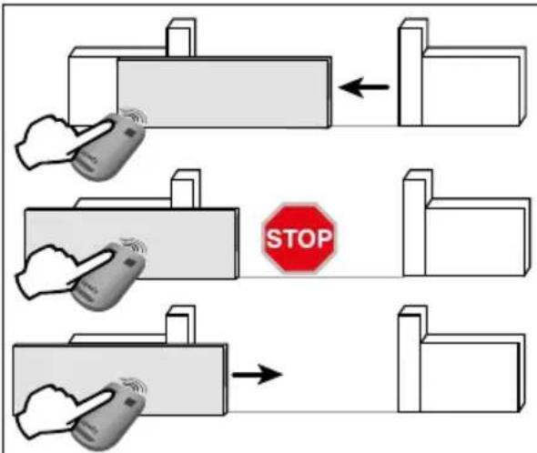
text_image
STOPtext_image
>2s RADIO P1 RESET somfy.natural_image
Technical line drawing of a mechanical assembly with cylindrical components and internal components (no visible text or symbols)
text_image
BATT - +natural_image
Diagram showing a hand interacting with a rectangular block and a vertical structure, no text or symbols presenttext_image
RADIO P1 RESET somfy. Somfy TaHomatext_image
RADIO P1 RESET somfy. x3 RADIO P1 RESET somfy.natural_image
Technical line drawing of a mechanical device with no visible text or symbolstext_image
RADIO 30% P1 RESET somfy.text_image
7 RADIO P1 RESET x2 RADIO P1 RESET somfy. somfy.text_image
RADIO P1 RESET somfy.text_image
RADIO P1 RESET somfy.natural_image
Mechanical device with lever and base, showing a close-up inset of a circular component (no text or symbols visible)natural_image
3D illustration of a device with a lid and base, showing internal components (no text or symbols)text_image
Diagram showing a device with a button labeled 'X' and an icon of a battery with cross symbols, alongside a magnified view.natural_image
Close-up of a computer mouse with a button labeled '+', showing no text or symbols on the mouse itself.natural_image
Diagram of a mechanical device with a rotating shaft and curved arrow indicating rotation (no text or symbols)natural_image
Diagram showing two views of a device with an arrow indicating transformation or assembly (no text or symbols present)natural_image
Illustration of a smartphone with an open rear panel and a circular button labeled '×' (no text or symbols on the main diagram)natural_image
3D mechanical assembly diagram showing a device with mounting holes and internal components (no text or symbols)text_image
Diagram illustrating the assembly of a free electrical device with labeled components and directional arrows indicating flow or assembly.text_image
Diagram of a wall assembly with labeled components A through J, showing structural connections and components.| Nummer Omschrijving |
| A Verlicht gebied |
| B Knipperlicht |
| C Antenne |
| D Contactstrip |
| E Foto-elektrische cellen |
text_image
G F E D B A somfy. RESET P1 30s RADIO connects with Somfy TaHomatext_image
Diagram showing three scenarios of building inspection with checkmarks and a red X mark, likely indicating failure or invalid status.natural_image
Diagram of a mechanical device with an arrow indicating rotational motion (no text or symbols present)text_image
Collection of tool icons with numbers 12, 17, and 25 indicating different types of tools or components.1

natural_image
Diagram of a sewing machine needle stitching metal parts on a cutting board (no text or symbols)natural_image
Mechanical assembly diagram showing a cylindrical component with multiple bolts and mounting holes (no text or labels)natural_image
Technical line drawing of a mechanical component with a black arrow pointing to a curved feature (no text or symbols)▶ De tandheugel vastmaken
natural_image
Four circular icons showing different types of tools: pen, screwdriver, drill bit, and wrench (no text or symbols)!
natural_image
Technical line drawing of a mechanical device with no visible text or symbols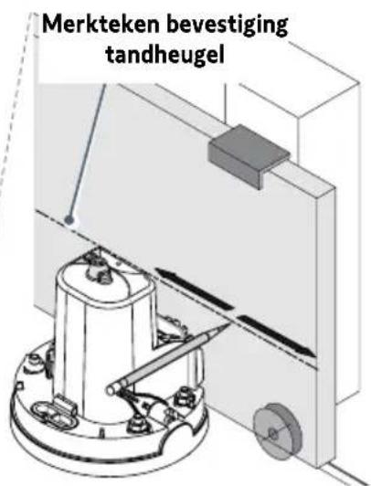
natural_image
Technical diagram of a mechanical assembly with rollers and a gear mechanism, showing alignment and assembly details (no text or symbols)natural_image
Diagram of a mechanical device with an arrow indicating rotational motion (no text or symbols)natural_image
Four circular icons showing different types of tools: screwdriver, pliers, switch, and cross (no text or symbols)
natural_image
Technical line drawing of a mechanical assembly with no visible text or symbolsnatural_image
Technical diagram of a mechanical assembly with two views of a device's internal components (no text or symbols visible)natural_image
Technical line drawing of a mechanical device with no visible text or symbolstext_image
Diagram showing a device control panel with labeled buttons and a hand pointing to the right button, highlighting a warning symbol.


text_image
Technical diagram of a mechanical component with labeled parts and directional arrows indicating assembly or assembly steps.
text_image
Technical diagram of a mechanical component with labeled parts and directional arrows indicating assembly or assembly steps.natural_image
Illustration of a gray rectangular device with wireless signal icons and a 'somy' logo at the bottom (no text or symbols on the device itself)
text_image
STOPtext_image
TX RX 1 2 1 2 BUSB 3 4C S
Installatie
text_image
>2S RADIO P1 RESET somfy.natural_image
Technical line drawing of a mechanical assembly with no visible text or symbols4.1 Voetgangersopening
natural_image
Diagram showing a hand interacting with a rectangular block and a right-hand block, illustrating a process or interaction (no text or symbols present)text_image
RADIO P1 RESET somfy. Somfy TaHomenatural_image
Technical line drawing of a mechanical device with no visible text or symbols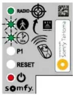
text_image
RADIO P1 RESET somfy.45
flowchart
graph LR
    A["Start"] --> B{P1}
    B -->|P1| C["RESET"]
    C --> D["somfy."]
    D --> E{P1}
    E -->|P1| F["RESET"]
    F --> G["somfy."]
    G --> H{P1}
    H -->|P1| I["RESET"]
    I --> J["somfy."]
    J --> K["End"]
text_image
RADIO P1 RESET somfy. x3 RADIO P1 RESET somfy.natural_image
Technical line drawing of a mechanical device with no visible text or symbolstext_image
RADIO 30% P1 RESET somfy.
text_image
7 RADIO P1 RESET x2 RADIO P1 RESET somfy. somfy.natural_image
Mechanical device with a lever and close-up inset showing a close-up of a mechanical component (no text or symbols visible)natural_image
3D illustration of a device with a curved handle and internal components, showing directional arrows (no text or symbols)- Steek de schroevendraaier in de gleuf en til de kap op.


natural_image
Close-up of a small electronic device with a circular button and an inset showing a resistor symbol (no text or labels visible)natural_image
Close-up of a computer mouse with a small circular button labeled '×' pointing to the interior (no text or symbols on the mouse itself)• Vervang de batterij (3 V CR 2430 of CR 2032).
12
natural_image
Diagram of a mechanical device with a rotating shaft and curved arrow indicating rotation (no text or symbols)natural_image
Diagram showing a device with a top view and a close-up of its internal structure, no text or symbols present.natural_image
Diagram of a smartphone showing internal components and a circular button with an 'X' symbol (no text or labels present)natural_image
3D diagram of a device with labeled components and internal structure (no text or symbols)text_image
Diagram illustrating the assembly of a free electrical device with labeled components and directional arrows indicating flow or assembly.text_image
Diagram of a wall assembly with labeled components A through J, showing structural connections and components.text_image
G F E D B A somfy. RESET P1 30s RADIO connects with Somfy TaHomatext_image
Diagram showing three scenarios of building inspection with checkmarks and a red X mark, likely indicating failure or invalid status.natural_image
Technical line drawing of a mechanical device with an arrow indicating rotation or movement (no text or symbols present)text_image
Collection of tool icons with numbers 12, 17, and 25 indicating different types of tools or components.1

natural_image
Mechanical assembly diagram showing a turning tool interacting with a component (no text or symbols visible)natural_image
Technical diagram of a mechanical assembly with bolts and a central component (no text or symbols)natural_image
Diagram of a mechanical component with a curved base and a small inset component, no visible text or symbolsnatural_image
Four circular icons showing different types of tools: pen, tool, drill bit, and wrench (no text or symbols)!
natural_image
Technical line drawing of a mechanical device with no visible text or symbols
natural_image
Technical diagram of a mechanical assembly with rollers and a gear mechanism, showing alignment and assembly details (no text or symbols)natural_image
Diagram of a mechanical device with an arrow indicating rotational motion (no text or symbols)natural_image
Four circular icons showing different types of tools: screwdriver, pliers, switch, and wrench (no text or symbols)
natural_image
Technical line drawing of a mechanical assembly with no visible text or symbolsnatural_image
Technical diagram of a mechanical assembly with two circular insets showing internal components (no text or labels)natural_image
Technical line drawing of a mechanical device with no visible text or symbolstext_image
Diagram showing a device control panel with labeled buttons and a hand pointing to the screen, featuring a warning symbol and 'Santry Telecom' logo.


text_image
Technical diagram of a mechanical component with labeled parts and directional arrows indicating assembly or assembly steps.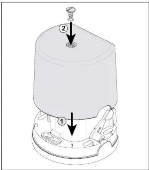
text_image
Technical diagram of a mechanical component with labeled parts and directional arrows indicating assembly or assembly steps.natural_image
Illustration of a smart home with wireless signal and control buttons (no text or symbols)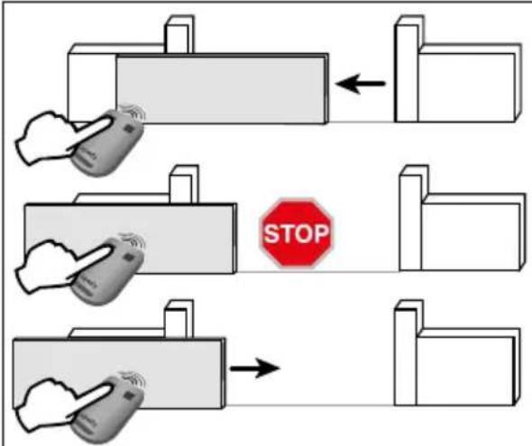
text_image
STOPtext_image
RADIO P1 RESET somfy.text_image
3 RADIO x3 P1 RESET somy. RADIO x3 P1 RESET somy.natural_image
Technical line drawing of a mechanical assembly with components and wiring (no visible text or symbols)natural_image
Three circular icons showing different types of tools: screwdriver, pliers, and pliers (no text or symbols)
text_image
LIGHT 14 15natural_image
Diagram showing a hand interacting with a rectangular block and a right-hand block, illustrating a process or interaction (no text or symbols present)text_image
RADIO P1 RESET somfy. Somfy To-Hometext_image
RADIO P1 RESET somy. x3 RADIO P1 RESET somy.natural_image
Technical line drawing of a mechanical device with a switch and lever mechanism (no text or symbols)