
GDK 700 - Garage door opener SOMFY - Free user manual and instructions
Find the device manual for free GDK 700 SOMFY in PDF.
| Product type | Garage door opener |
| Brand | Somfy |
| Model | GDK 700 |
| Power supply | 230 V - 50 Hz |
| Power consumption (standby) | 4 W |
| Power consumption (operation) | 120 W |
| Maximum pulling force | 700 N |
| Maximum speed | 14 cm/s |
| Maximum use | 20 cycles per day |
| Climatic conditions | -20 °C to +60 °C, dry interior IP20 |
| Integrated lighting | LED, 30 s delay after movement |
| Radio frequency | 433.42 MHz, < 10 mW |
| Number of storable channels | 32 |
| Obstacle detection | Integrated, adjustable sensitivity on 4 levels |
| Limits | Mechanical stop at opening, electronic at closing |
| Manual release | Yes, by cord (max height 1.80 m) |
| Connectable accessories | Photoelectric cells, flashing light, remote antenna, backup battery, key switch, solar kit |
| Remote control battery | 3 V CR2430, lifespan approximately 2 years |
| Maintenance | Periodic checks, battery replacement |
| Safety standards | EN 12453 (obstacle detection), parameter locking |
Frequently Asked Questions - GDK 700 SOMFY
User questions about GDK 700 SOMFY
0 question about this device. Answer the ones you know or ask your own.
Ask a new question about this device
Download the instructions for your Garage door opener in PDF format for free! Find your manual GDK 700 - SOMFY and take your electronic device back in hand. On this page are published all the documents necessary for the use of your device. GDK 700 by SOMFY.
USER MANUAL GDK 700 SOMFY
Installation and operating guide
Sommaire
-Kit contents 2
- Space requirements 3
- General view of the installation 3
Field of application 4
- Types of doors which can be motorised 4
Maximum dimension of doors 4
Prerequisites for installation 5
- Tools and screws necessary for installation (not supplied) 5
- Recommendations for fastening (screws not included in the kit) 5
1 Installation 6
1.1 Implementation of fastenings 6
- Fastening the lintel and door brackets 7
1.2 Assembly 8
- Assembling the rail in 3 sections 8
- Assembling the rail to the motor head 10
- Fastening the unit to the ceiling 11
1.3 Mounting 11
- Fastening the unit to the lintel bracket 11
- Fastening the unit to the ceiling 11
- Fastening the link arm to the door and the carriage 12
1.4 Settings 13
- Adjusting and fastening the opening stop 13
- Checking the tension of the belt 13
1.5 Assembling/disassembling the cover 14
1.6 Electrical connection to the power supply 14
2 Programming 15
2.1 Parameter setting 15
- Description of the programming buttons 15
- Performing auto-programming 15
- Checking the mechanical setting of the door 17
2.2 Advanced settings 17
2.3 Locking/unlocking the parameters menu 19
2.4 Memorising the remote controls 20
2.5 Clearing the remote controls 21
2.6 Reinitialising the settings 21
3 Operation 22
3.1 User training 22
3.2 Using the remote controls 22
-Using the remote control with door closed 22
-Using the remote control with door open 23
-Using a 3-button remote control 23
3.3 Obstacle detection mode 24
3.4 Integrated lighting operation 24
3.5 Manual back release mode 25
3.6 Operation after a power outage 25
4 Accessories 26
4.1 Connecting the photoelectric cells 26
4.2 Connecting the flashing light 26
4.3 Connecting the remote antenna 27
4.4 Connecting the back-up battery 27
4.5 Connecting the key contact 28
4.6 Connecting the solar kit 28
4.7 Accessories general wiring diagram 29
5 Maintenance and repairs 30
5.1 Periodic checks 30
5.2 Diagnostics 30
5.3 Assistance 30
5.4 Changing the remote control battery 31
6 Technical data 32

We recommend you have at least two people to install this product.
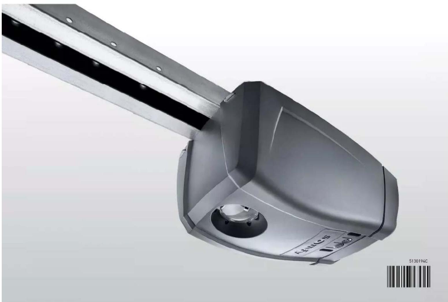
Product presentation
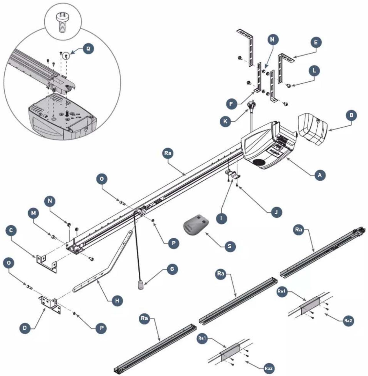
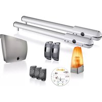
Kit contents
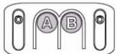
| Mark | Designation | |
| A | Motor head x 1 | |
| B Flap x 1 | ||
| C Lintel bracket x 1 | ||
| D Door bracket x 1 | ||
| E Ceiling mounting bracket x 2 | ||
| F Motor head mounting bracket x 2 | ||
| G Manual back release device x 1 | ||
| H Connecting arm x 1 | ||
| I End limit stop x 1 | ||
| J TCB-H 4.2x13 zn self-tapping screws x 2 | ||
| K Power supply cord x 1 |
| Mark | Qty | Designation |
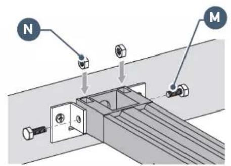
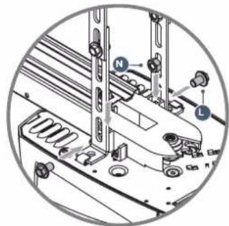
| L | TH10 M8x12 zn washer screws | x 4 |
| M | TH M8x16 zn screws | x2 |
| N | HU8 nut | x 6 |
| O Shaft | x 2 | |
| L Circlips | x 2 | |
| Q Thread-forming screws Ø 4x8 (motor head) | x 4 | |
| Ra | 3-part rail | x 1 |
| Ra1 | Sleeve | x 2 |
| Ra2 | Thread-forming screws Ø 4x8 (sleeves) | 2 x 4 |
| S Remote control | x 2 | |
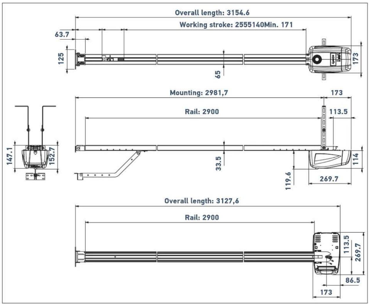
Space requirements
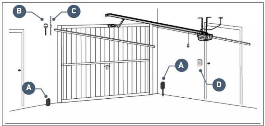
General view of the installation

if the garage door is the sole means of access to the garage, install an external back release device (ref. 2400658 or ref. 9012962).
| Mark Designation Type of cable | ||
| A | Photoelectric cells 4 x 0.5 mm | 2 (RX receptor cell) 2 x 0.5 mm² (TX emitter cell) |
| B Flashing light 2 x 0.5 mm | 2 | |
| C Aerial - | ||
| D Key | lock 2 x 0.5 mm² | |
Area of application
This drive is exclusively intended to equip a garage door designed for residential use.
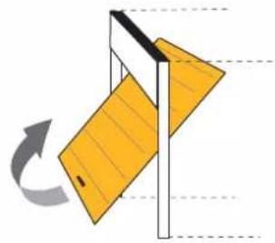
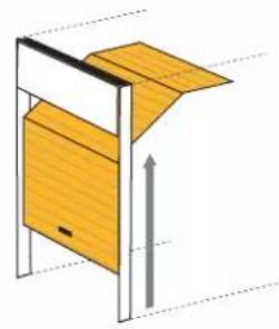
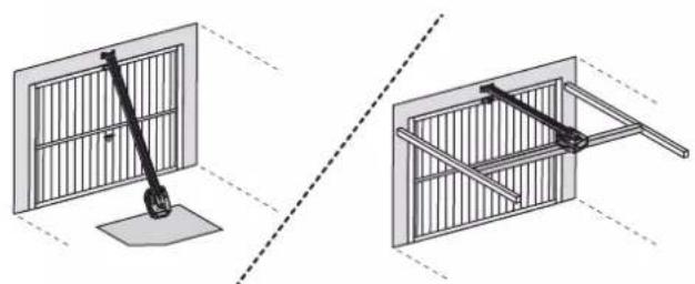
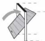
Types of doors which can be motorised
Up-and-over door Sectional door
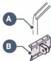
i
If the upper profile
A of the panel is specific, use the mounting bracket B for sectional door, ref.:9009390.
Maximum dimension of doors
Up-and-over door and sectional door
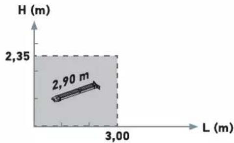
Max. surface area = 7 m²
Max. weight = 70kg

Prerequisites for installation
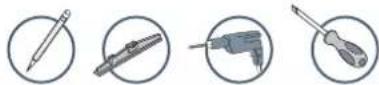
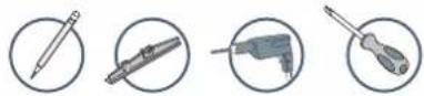
Tools and screws necessary for installation (not supplied)
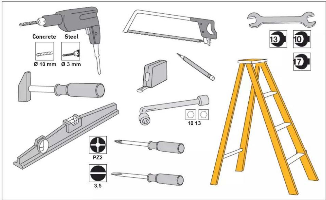
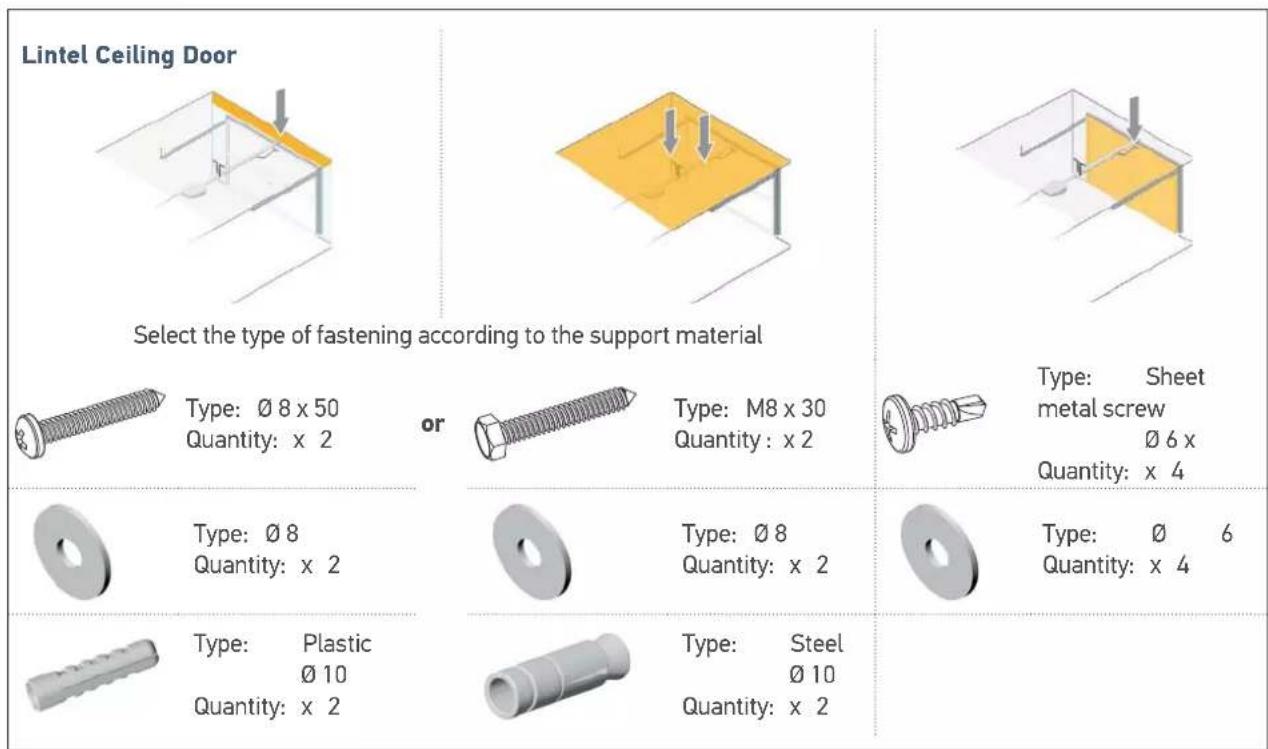
Recommendations for fastening (screws not included in the kit)
30
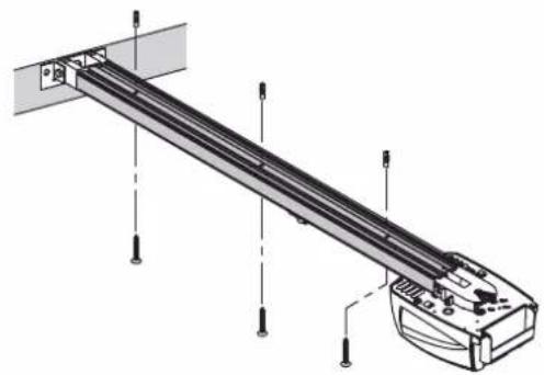
1.1 Implementation of fastenings
Measure the distance "D" between the highest point of the door and the ceiling.
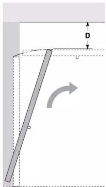
Case 1: Drive against ceiling
If "D" is between 35 and 200mm secure the assembly directly to the ceiling.
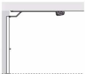
35 < D < 200
i
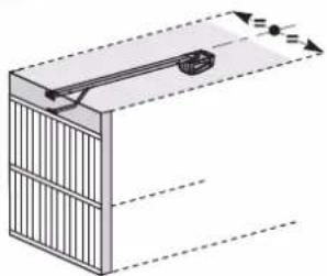
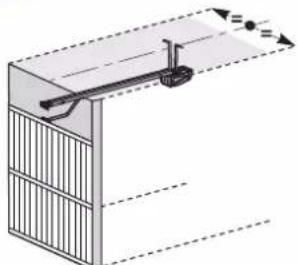
Case 2: Drive not against ceiling
When installing, centre the assembly in relation to the garage door.
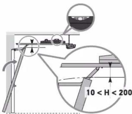
If "D" is greater than 200 mm, secure the assembly so that the height "H"* is between 10 and 200 mm.
* H = distance between the bottom of the rail and the highest point of the door.
D>200
i
When installing, centre the assembly in relation to the garage door.

To facilitate taking dimensions on the lintel; once "D" has been measured, determine "H" by subtracting 10 from 200mm from "D". Then mark this value on the lintel from the ceiling. The mark indicates the lower position of the lintel bracket.
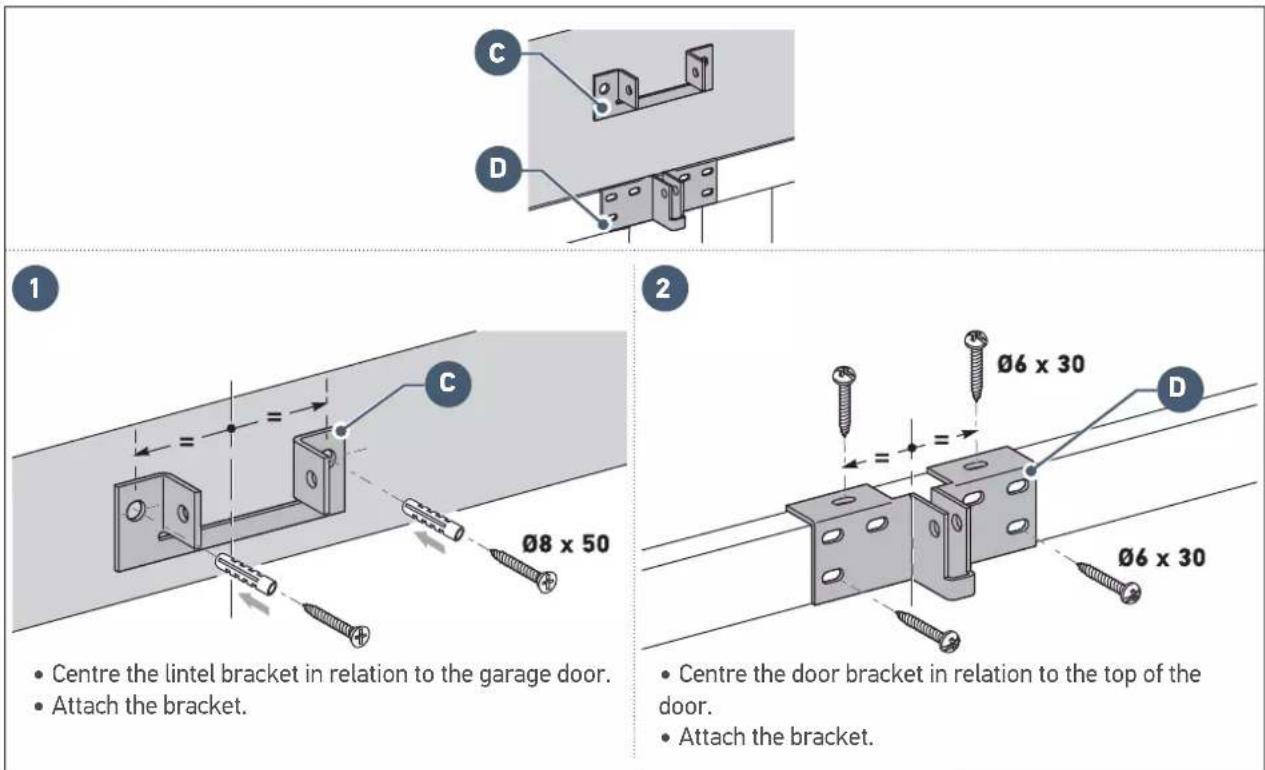
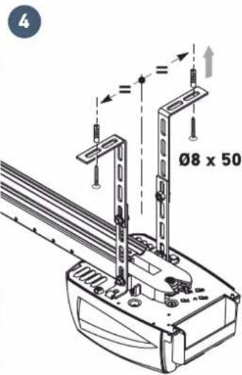
Fastening the lintel and door brackets
Case 1: Drive against ceiling
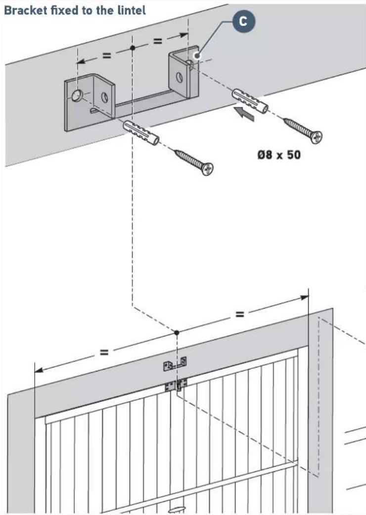
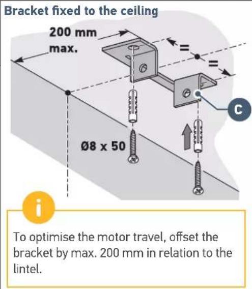

- Centre the lintel bracket in relation to the garage door.
- The bracket can be fastened either to the lintel or directly to the ceiling.

- Centre the door bracket in relation to the top of the door.
- Attach the bracket.
Case 2: Drive not against ceiling
1.2 Assembly

Assembling the rail in 3 sections
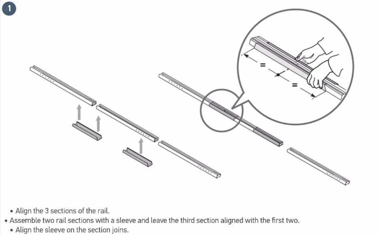
Check that the belt inside of the rail is not twisted.

- Fit the belt into the rail.
- Assemble the motor head mounting end piece to the rail.
- Fit the third section end piece to the second section.
- Assemble the lintel bracket end piece on the rail.
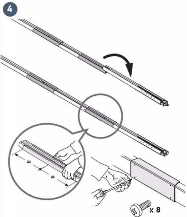
- Align the third section with the two other sections, then assemble using a sleeve.
- Align the sleeve to the join of the sections.
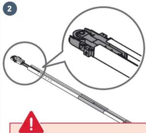
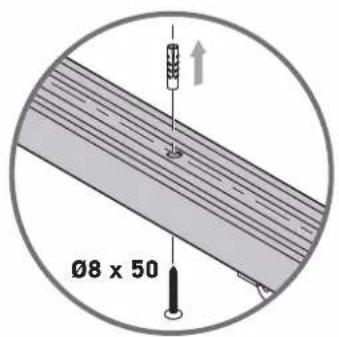
Tighten the sleeves to the rail using screws WITHOUT DRILLING THE RAIL.

The mounting screws must not drill the rail. The body of the screw must remain visible.
- Move the carriage in the middle of the rail.
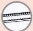
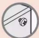
Assembling the rail to the motor head


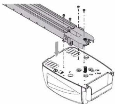
1
- Insert the motor shaft into the rail pinion, then mount the assembly using engine head screws
Q
2
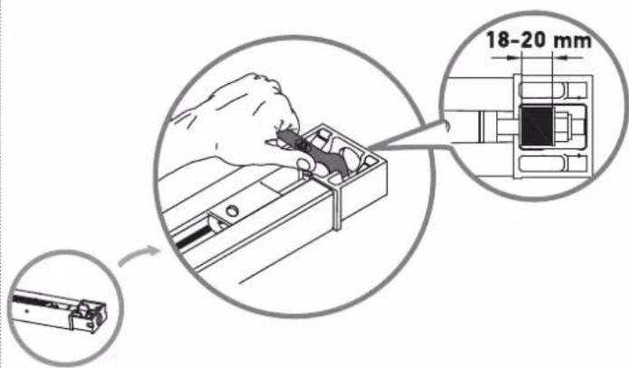
- Tighten the nut to tauten the belt.
- The rubber squashes when tightened.
To obtain the correct tension, the rubber should measure between 18 and 20mm
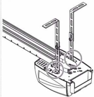
1.3 Mounting
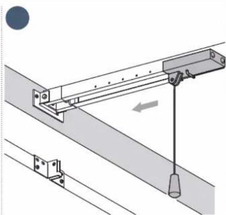
Fastening the unit to the lintel bracket

1
- Position the assembly in the lintel bracket by placing the motor head on the ground or the on cross member.
2
- Fasten the assembly to the lintel bracket.
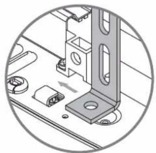
Fastening the unit to the ceiling
Case 1: Drive against ceiling
- Fasten the rail to the ceiling.
Case 2: Drive not against ceiling
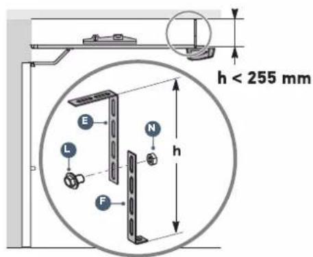
1
- Fasten the unit at the motor head.
2
Case 2: Drive not against ceiling (continued)
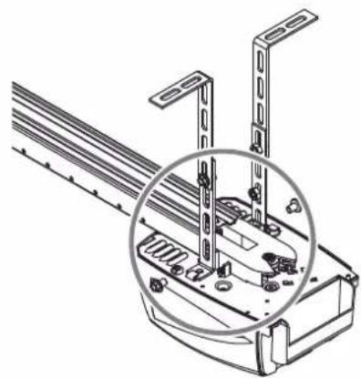
3

For an adjustable intermediate mounting along the rail, or mounting at a distance "h" of between 250 mm and 550 mm, use the ceiling mounting kit (ref.: 9014462).
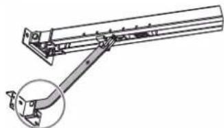
Fastening the link arm to the door and the carriage

If the back release handle is higher than 1.80m it will be necessary to extend the cable to make it accessible to all users.
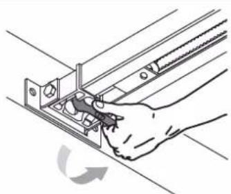
- Release the carriage using the manual back release device.
- Bring the carriage level with the door.
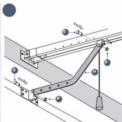
- Secure the arm to the door bracket and carriage.
Fastening the link arm to the door and the carriage (continued)

Depending on the configuration, it may be necessary to cut the link arm.

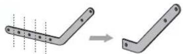
1
2
The section of the link arm fixed to the door bracket must be as horizontal as possible.
1.4 Settings
Adjusting and fastening the opening stop


During this operation, check that there is no risk that the back release device cable will subsequently become snagged on an element protruding from the car (for example a roof rack).
1
- Release the carriage using the manual back release device and move the door to the open position.
Do not open the door fully, but position it so that it does not reach its stops.
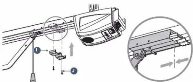
2
Position the stop against the carriage.
- Mark the mounting holes.
- Drill the holes with 3 mm drill bit.
Fix the stop using the self-tapping screw.
Checking the tension of the belt

If necessary, adjust the belt tension.

The tension rubber must never be fully compressed: to obtain the correct tension, the rubber should measure between 18 and 20mm (see page 10).
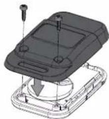
1.5 Assembly/Disassembly of the motor cover
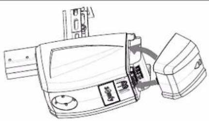
- Reassemble the cover as shown in the diagram above: first, position the lower section of the cover in the groove then clip the upper section into place.
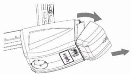
- Remove the cover as shown in the diagram above: first, unclip the upper section of the cover then remove the lower section (without forcing it).
1.6 Electrical connection to the power supply

DANGER
Connect the power supply cable to a socket which complies with electrical requirements (see safety instructions, chapter 4).
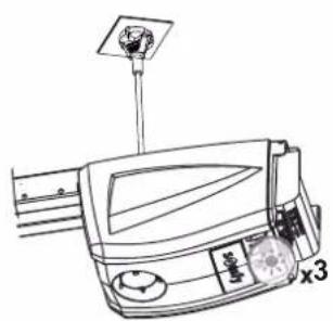
- Connect the motor to the power supply.
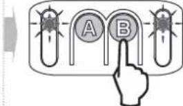
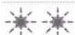
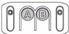
The integrated lighting flashes 3 times: the motor is switched on. Indicator light "B" flashes twice continuously: the drive is waiting for auto-programming.
2.1 Parameter setting
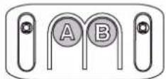
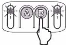
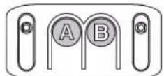
Description of the programming buttons
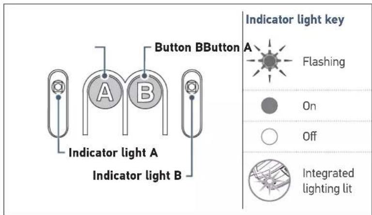
| Functions of buttons and indicator lights | |
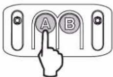
| Button A | ·Using forced operating mode ·Enters and exits the settings menu ·Selecting a setting |
| Button B • Triggers auto-programming ·Memorising/clearing the remote controls ·Modifying the value of a setting | |
| Indicator light A | ·Parameter indicator light selected |
| Indicator light B | ·Parameter value indicator light ·Fault indicator light |
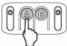
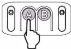
Performing auto-programming
2 specific cases:
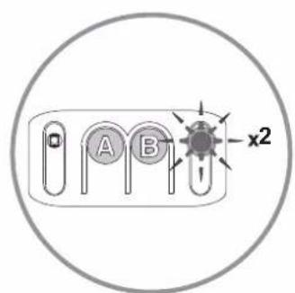
Case 1: No indicator light flashes auto-programming mode must be selected.
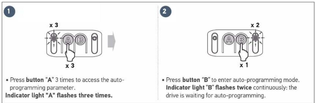
Case 2: Indicator light "B" flashes twice continuously the drive is waiting for auto-programming (case during installation).

3
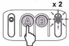
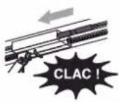
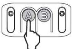
Control the motor using button "A" (continuous pressure) so that the transmission shuttle is engaged on the carriage.
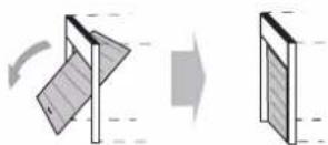
- Maintain button "A" depressed to bring the door to closed position.
NB: If button "A" is released, the shuttle stops. If button "A" is kept depressed again, the shuttle moves in the opposite direction to the previous movement.

Release button "A" before the motor exerts too much pressure on the door.
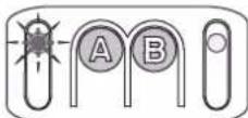
4
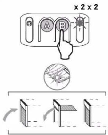
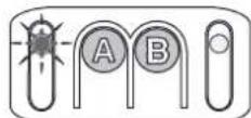
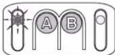
- Press button "B" to launch the auto-programming cycle. The door performs a complete Opening-Closing cycle.
If the auto-programming is correct, indicator light "B" goes out.
If the auto-programming cycle was not successful, indicator light "B" flashes twice. In this case, start a new auto-programming cycle using button "B".

During the auto-programming cycle: If the door is moving, the movement is stopped and auto-programming is interrupted if any of the buttons are pressed.
Note: The motor is again awaiting auto-programming (see case no.2 - figure 3).
- Checking the mechanical setting of the door
After auto-programming, perform manual back release of the drive to check that the door has not been closed too strongly.
- Back release occurs normally, without any resistance or sudden movement: the door has been closed correctly.
- Back release is impossible or abnormal resistance is observed: re-run auto-programming while closing the door more "gently" (see page 15 - case no.1).

WARNING
- At the end of installation, it is essential to check that the obstacle detection complies with appendix A of standard EN 12453.
- Failure to follow this instruction may result in serious injury, e.g. due to crushing by the gate.
2.2 Advanced settings

The programming procedures below must only be followed if you want to change the default value of the parameters.

To save the parameters selected, press button A successively until the LEDs go out. By default, the parameters are automatically saved after a 2-minute time-out after which the electronics switch to standby.
Choice of obstacle detection sensitivity

x1Nx1N
- Press button "A" repeatedly until indicator light "A" flashes once. "Obstacle detection sensitivity" mode is activated.
- The number of times "N" that indicator light "B" flashes indicates the value of the parameter, see table below).

- Press button "B" to change the value of the parameter.

Press the button "A" five times to exit the settings menu.
Indicator light A Obstacle detection sensitivity
Indicator light B
| very low sensitivity |
| low sensitivity |
| Standard (default value) |
| high sensitivity |

WARNING
If this parameter is changed, it is essential to check that the obstacle detection complies with appendix A of standard EN 12453. Failure to follow this instruction may result in serious injury, e.g. due to crushing by the gate.
Choice of docking zone when closing

x2Nx2N
- Press button "A" repeatedly until indicator light "A" flashes twice. "Docking zone when closing" mode is activated.
The number of times "N" that indicator light "B" flashes indicates the value of the parameter, see table below).

- Press button "B" to change the value of the parameter.

Press the button "A" four times to exit the settings menu.
Indicator light A
Indicator light B

Docking zone when closing
No slowing No reduction in speed at the end of closing.
Short slowing (default value)
The speed is reduced during the last 20 centimetres.
Long slowing The speed is reduced during the last 50 centimetres.

WARNING
If this parameter is changed, it is essential to check that the obstacle detection complies with appendix A of standard EN 12453. Failure to follow this instruction may result in serious injury, e.g. due to crushing by the gate.
Choice of type of power supply

x5Nx5N
- Press button "A" repeatedly until indicator light "A" flashes five times. "Type of power supply" mode is activated.
The number of times "N" that indicator light "B" flashes indicates the value of the parameter, see table below).

- Press button "B" to change the value of the parameter.

Press the button "A" once to exit the settings menu.
Indicator light A Power supply type
Indicator light B


Mains power supply (default type of power supply)
Solar power

WARNING
- Parameter programming is now complete; the parameters menu must always be locked to ensure the safety of users.
- Failure to follow this instruction may result in serious injury, e.g. due to crushing by the gate.
2.3 Locking/unlocking the parameters menu
Locking the parameters menu

- Press button "A" repeatedly until indicator light "A" flashes four times. "Parameter menu locking" mode is activated.

- Press button "B" once. Indicator light "A" goes out. The parameters menu is locked.
Indicator light A Locking the parameters menu
Indicator light B

the parameters menu is locked

If button B is pressed accidentally, move on to the "Unlocking the parameters menu" step

At this stage in the installation, the drive is operational. The remote controls supplied in the kit have already been memorised.
Unlocking the parameters menu

WARNING
The keypad for setting the parameters is locked to ensure the safety of the users. The parameters must only be unlocked and adjusted by a professional drive and home automation installer. Making any changes which do not comply with these instructions could risk personal injury or damage to property. Somfy cannot be held responsible for any damages resulting from non-compliance with these instructions.

If the parameters menu is locked and no memorised remote control is available, it will be necessary to memorise a remote control first (see page 20).

- Press and hold button "A".

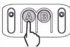
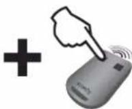


- Without releasing button "A", press a button on a remote control which is already memorised. The integrated lighting comes on briefly to indicate that unlocking has taken place.

- Release button "A".
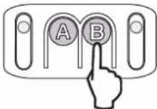
2.4 Memorising the remote controls
Memorising the remote controls for operation in "Total opening" mode
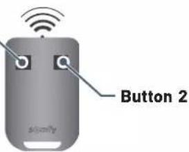
Button 1

- Button 1 on the remote controls supplied in the kit has already been memorised.
- If this procedure is carried out using a button which has already been memorised, the button will be cleared.

2s


5s
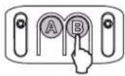
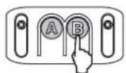
- Press button "B" for 2 seconds.
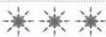
The integrated lighting comes on.
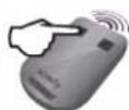
- Press the button on the remote control
The integrated lighting flashes for 5 seconds.
The remote control button has been memorised.
Memorising a Telis type remote control or similar (not supplied in the kit)

2s

- Press button "B" for 2 seconds. The integrated lighting comes on

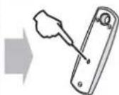

5s
- Using a thin implement, press the "prog" button on the back of the remote control.
The integrated lighting flashes for 5 seconds. The remote control has been memorised.
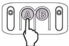
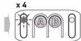
2.5 Clearing the remote controls

This procedure causes all memorised remote controls to be cleared.
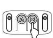
7s
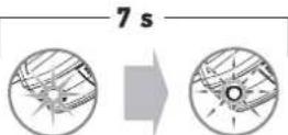
5s
- Press button "B" for 7 seconds. The integrated lighting comes on then begins to flash (5 seconds).

All the remote controls and all the settings are now cleared.
2.6 Reinitialising the settings
To reinitialise all settings, simply run a new auto-programming process (see page 15).
3.1 User training

WARNING
- Any potential user must be trained by the installer in using the drive, applying all the recommendations in this manual. It is essential to ensure that no untrained persons are able to put the door into motion.
The user must monitor the door as it moves and keep people away from it until the door is completely open or closed. - Do not allow children to play with the door control devices. Keep remote controls out of the reach of children.
- Do not deliberately prevent the door from moving.
- This drive may be used by children aged 8 and over and by persons whose physical, sensory or mental capacity is impaired, or by persons with little experience or knowledge, as long as they are under supervision or have received instructions on safe use of the drive and fully understand the associated risks. Children must not be allowed to play with the drive. Children must not be allowed to clean or maintain the unit.

All users must be trained on how to safely use this door (standard use and locking principle) and on the mandatory periodic checks.
3.2 Using the remote controls
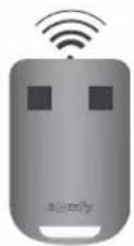

The indicator light on the remote control confirms that it functions correctly.
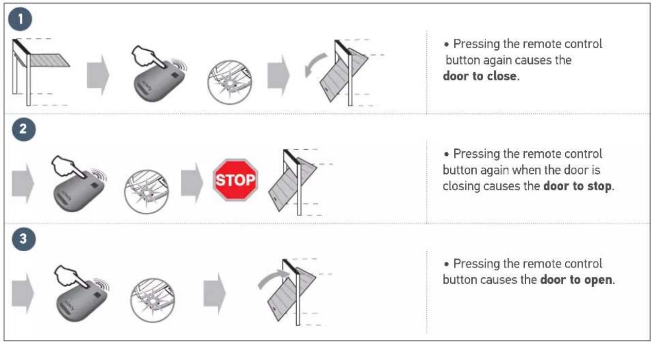
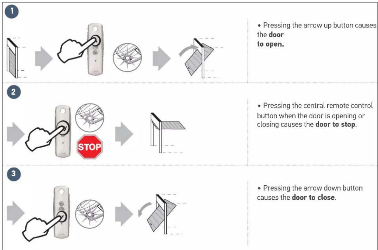
Using the remote control with door closed
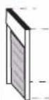
1


- Pressing the remote control button causes the door to open.

2


- Pressing the remote control button again when the door is opening causes the door to stop.

3


- Pressing the remote control button again causes the door to close.
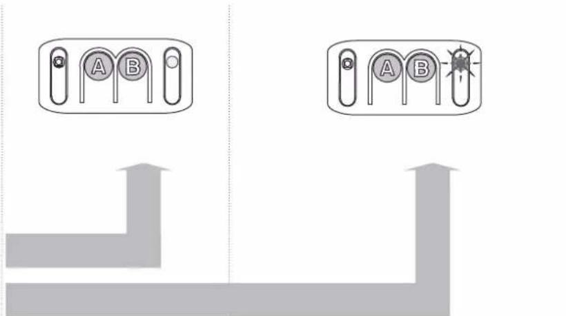
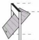
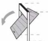
Using the remote control with door open
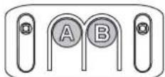
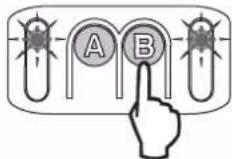
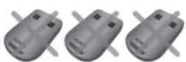
Using a 3-button remote control
3.3 Obstacle detection mode

The obstacle detection function operates up to 5cm from the ground. It is intrinsic to the drive and operates without any accessories (photoelectric cells).
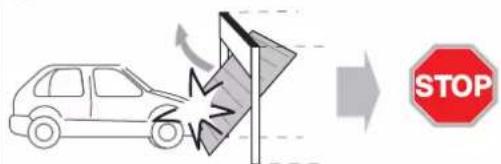
1
- When an obstacle is detected during opening, the door will stop.
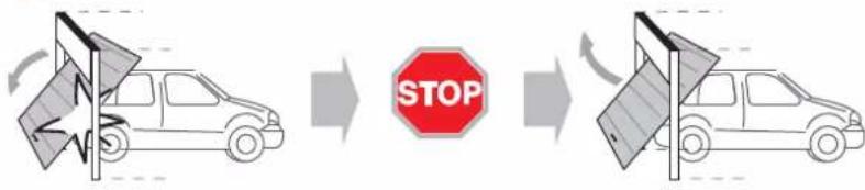
2
- When an obstacle is detected during closing, the door will stop then open again.
3.4 Integrated lighting operation
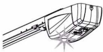
- The integrated lighting comes on each time the drive is switched on. When the door stops moving, it goes off automatically after 30 seconds.

Repetitive use will cause the integrated lighting to be lit constantly which may result in the light being switched off automatically due to thermal protection.
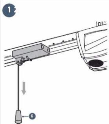
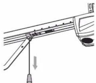
3.5 Manual back release mode
The drive is equipped with a manual back release device which makes it possible to manipulate the door manually, for example in the event of an electrical fault. This device must be able to be accessed easily (at a maximum of 1.80 m from the ground).

WARNING
- When releasing the drive, an incorrect balance may result in sudden movements which may be dangerous.
- Only use the cord to release the drive. Never use the cord to manipulate the door manually.
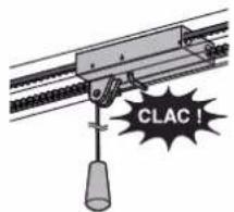
- It is essential that the drive is re-engaged before any new commands.
1
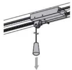
- Release the drive by pulling the cord until the door drive system is released.
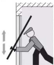
- Move the door manually (possible as long as the drive system is disengaged).
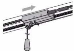
- Re-engage the drive by moving the door manually until the drive mechanism re-locks on the transmission rail.

WARNING
The yellow warning sticker concerning the risk of crushing and the description of how to move the door manually must be displayed inside the garage.
3.6 Operation after a power outage
Following a power outage, the drive must recognise its "fully open" position again.
- Open the door fully using a memorised remote control.
- The door will open at a reduced speed.

Allow the door to open to its "fully open" position.

DANGER
Switch the electrical power supply to the drive off before installing any peripheral.
4.1 Connecting the photoelectric cells
The photoelectric cells allow the presence of an obstacle to be detected when opening/closing the door. An obstacle placed between the cells will prevent the door from closing. If an obstacle is detected when the door is closing, the door stops then reopens.
The integrated lighting is activated intermittently for 30 seconds.
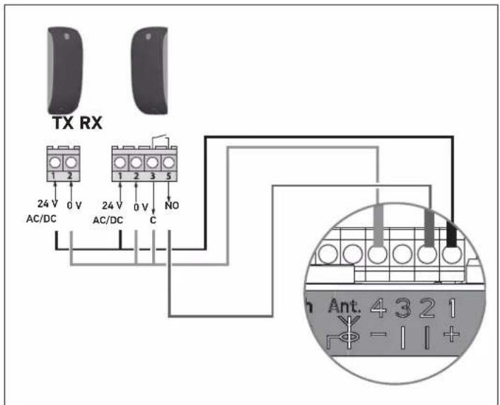
i
When positioning the cells, remove the bridge created between terminals "1" and "2" of the motor electronics.

If the cells are disconnected, it is essential to recreate the bridge between terminals "1" and "2".
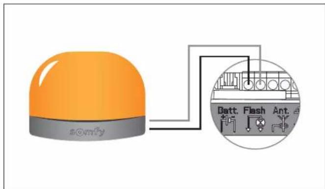
4.2 Connecting the flashing light
The flashing light is activated whenever the door moves, with a 2-second pre-warning before movement starts.
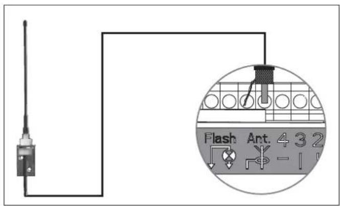
4.3 Connecting the remote antenna
The remote antenna allows the radio range between the remote control and the drive to be increased.
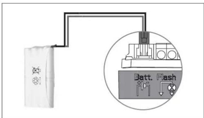
4.4 Connecting the back-up battery
Operation
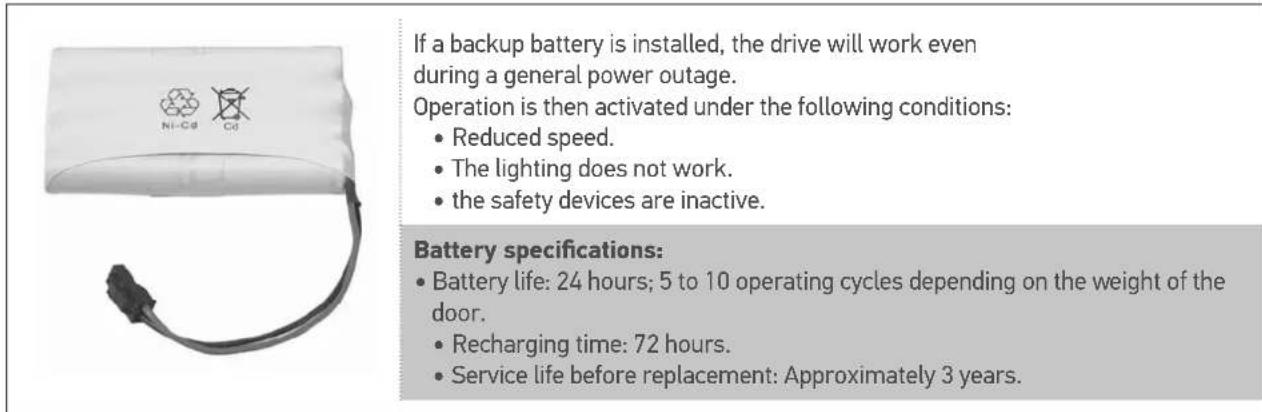

For optimum battery life it is recommended that the main power supply be switched off and the drive operated using the battery for several cycles, three times a year.
Connection
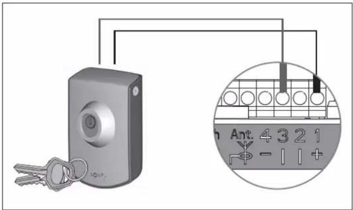
4.5 Connecting the key contact
The key contact serves to control the moving and lighting of the motorised garage door.
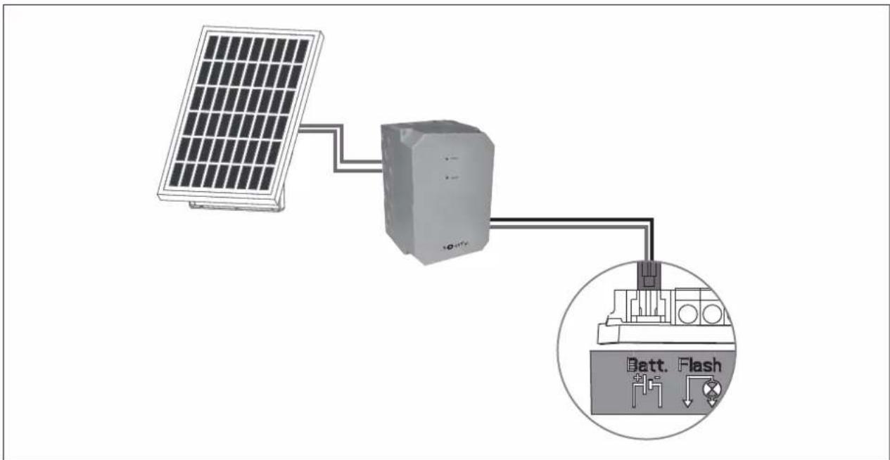
4.6 Connecting the solar kit

Refer to the solar panel guide.
4.7 Accessories general wiring diagram

DANGER
Switch the electrical power supply to the drive off before installing any peripheral.
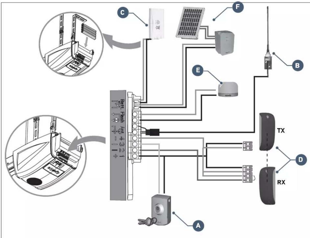
| Mark Designation | |
| A | Key lock |
| B Offset aerial | |
| C | Backup battery |
| D | Photoelectric cells |
| E | Flashing light |
| F | Solar kit |
5.1 Periodic checks

WARNING
Refer to the Safety instructions booklet, chapter 9 - "Safety instructions relating to maintenance".
5.2 Diagnostics
Indicator light A
Indicator "A" does not light up when button "A" is pressed.
The keypad is locked. To unlock the keypad, see "2.3 Locking/Unlocking the settings menu".
Indicator light B
| Indicator light B Meaning Solution? | |||
| 2 | Motor waiting for auto-programming. | Start auto-programming | |
| 3 | Cell fault. | Check that no obstacles prevent the cells from detecting. Check the wiring of the cells or create a bridge between terminals 1 and 2 if no cells are installed. Check the correct alignment of the cells. | |
| 5 | Motor thermal protection device | Leave the motor to cool until the fault disappears. | |
| 6 | Motor current measuring circuit fault or sensor fault. | Switch off the power supply (mains and backup battery), wait a few minutes then reconnect the power supply. Perform an auto-programming cycle. If the fault persists, contact Somfy technical support. | |
| 7 | Maximum power delivered by the motor reached during the auto-programming phase. | Product has reached operating limit. | |
5.3 Assistance
If the fault remains or for any other problem or enquiry relating to your drive, visit www.somfy.com
5.4 Changing the remote control battery
The service life of the battery is generally 2 years.
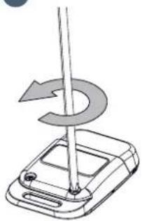
1
Unscrew the rear of the remote control.
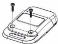
- Remove the screws.
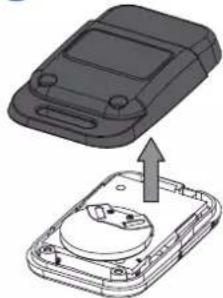
- Remove the rear of the remote control.
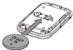
- Replace the battery (3 V CR 2430).
- Refit and screw on the rear of the remote control.
| General specifications | ||
| Power supply 230 V - 50 Hz | ||
| Max. power consumption | Standby 4 W | |
| Operation 120 W | ||
| Max. tensile force 700 N | ||
| Operation: Number of opening-closing cycles per day | Max. 20 cycles per day tested for 10,000 cycles | |
| Maximum speed 14 cm/s | ||
| Programming interface 2 buttons - 2 indicator lights | ||
| Climatic operating conditions - 20 °C / + 60 °C - dry interior IP 20 | ||
| End limits | • Opening mechanical stop • Electronic when closing: stored closing position | |
| Electrical insulation | Class 2: double-insulated ☐ | |
| Integrated lighting LED | ||
| Radio frequency 433.42 MHz - < 10 mW | ||
| Number of storable channels 32 | ||
| Connections | ||
| Safety input | Type Dry contact: NF | |
| Compatibility TX/RX | photoelectric cells | |
| Wired control input | Dry contact: NO | |
| Flashing light output | 24 V - 15 W | |
| Accessories power supply output | 24 V - 500 mA max. | |
| Offset aerial input | Yes: RTS antenna compatible | |
| Backup battery input | Battery life | Yes: battery pack compatible |
| Recharging time | 24 hours / 5 to 10 cycles depending on the door | |
| 72 hours | ||
| Operation | ||
| Forced operating mode | By pressing and holding button “A” | |
| Timed lighting (after movement) | Fixed: 30 s | |
| Flashing light pre-warning | 2 secs automatic if light connected | |
| Security entry operation | When closing | Total reopening |
| Before opening (ADMAP) | With | |
| Integrated obstacle detection | Adjustable sensitivity: 4 levels | |
| Operation in the event of obstacle detection | Total reopening | |
| Gradual starting Yes | ||
| Opening speed | Fixed: 14 cm/s (max.) | |
| Closing speed | Fixed: 12 cm/s (max.) | |
| Docking speed when closing | Programmable: no reduction in speed, short slow zone (20 cm), long slow zone (50 cm) | |
Somfy France
0 820 055 055 (0,15€ la minute)
Forum d'entraide: forum.somfy.fr
SomfyGmbh
07472/930-495
www.somfy.de
Somfy LLC Russia
8 (800) 555-60-70
www.somfy.ru
- Sommaire
- Field of application 4
- Prerequisites for installation 5
- Installation 6
- Programming 15
- Operation 22
- Accessories 26
- Maintenance and repairs 30
- Technical data 32
- Product presentation
- Kit contents
- Area of application
- i
- Prerequisites for installation
- Implementation of fastenings
- Assembly
- Mounting
- Settings
- Assembly/Disassembly of the motor cover
- Electrical connection to the power supply
- DANGER
- Parameter setting
- specific cases:
- - Checking the mechanical setting of the door
- WARNING
- Advanced settings
- Choice of obstacle detection sensitivity
- Indicator light A Obstacle detection sensitivity
- Indicator light B
- Locking/unlocking the parameters menu
- Memorising the remote controls
- Clearing the remote controls
- Reinitialising the settings
- User training
- Using the remote controls
- Obstacle detection mode
- Integrated lighting operation
- Manual back release mode
- Operation after a power outage
- Connecting the photoelectric cells
- Connecting the flashing light
- Connecting the remote antenna
- Connecting the back-up battery
- Connecting the key contact
- Connecting the solar kit
- Accessories general wiring diagram
- Periodic checks
- Diagnostics
- Assistance
- Changing the remote control battery
- Somfy France
- SomfyGmbh
- Somfy LLC Russia
Brand : SOMFY
Model : GDK 700
Category : Garage door opener