
Freevia Line - Garage door opener SOMFY - Free user manual and instructions
Find the device manual for free Freevia Line SOMFY in PDF.

| Product type | Sliding garage door opener |
| Brand | Somfy |
| Model | Freevia Line |
| Compatible gate | Sliding, PVC/wood/metal, max length 7 m, max weight 500 kg |
| Power supply | 230 V~ 50 Hz / 24 V (solar optional) |
| Motor power | 120 W |
| Maximum power consumption | 600 W (with zone lighting) |
| Standby consumption | 3.5 W |
| Maximum frequency of cycles | 20 cycles/day (10 cycles/day with solar) |
| Opening time | 16 s (for a 150 kg / 3 m gate) |
| Operating temperature | -20 °C to +60 °C |
| Protection rating | IP 44 |
| Thermal protection | Yes |
| Integrated radio receiver | Yes, frequency 433.42 MHz, range approx. 30 m |
| Max number of programmable remote controls | 16 |
| Available outputs | Flashing light (24 V, 10 W max), zone lighting (230 V, 500 W max halogen/incandescent), accessory power supply (24 Vdc, 15 W max) |
| Available inputs | Photocells (BUS), backup battery (BATT), dry contact (START), remote antenna |
| Motor dimensions (approx.) | 232 x 180 x 109 mm |
| Weight (approx.) | 8 kg |
| Obstacle detection | Compliant with EN 12453 standard |
| Main functions | Total opening/closing, pedestrian opening, automatic closing, adjustable speed, self-learning travel |
Frequently Asked Questions - Freevia Line SOMFY
User questions about Freevia Line SOMFY
0 question about this device. Answer the ones you know or ask your own.
Ask a new question about this device
Download the instructions for your Garage door opener in PDF format for free! Find your manual Freevia Line - SOMFY and take your electronic device back in hand. On this page are published all the documents necessary for the use of your device. Freevia Line by SOMFY.
USER MANUAL Freevia Line SOMFY
Operating and installation guide

Sommaire
!
!

i
- Contents of the pack 2
- Space requirements 3
- Field of application 3
- General view of the installation 3
- Presentation of the control electronics 4
Prerequisites for installation 5
- Stop blocks on the ground 5
- Positioning the motor 5
- Electrical preequipment 5
- Cables required 6
-
Concrete base 7
-
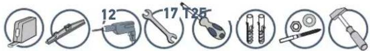
Tools require for installation (not provided) 8
- Screws etc. required for installation of the rack and pinion (not provided) 8
1 Installation 9
1.1 Unlock the motor 9
1.2 Installing the motor 9
- Fastening the motor to the ground 9
- Fastening the rack and pinion 10
1.3 Checking the installation of the motor 11
1.4 Locking the motor 11
1.5 Wiring the motor 12
1.6 Connecting to the 230V power supply 13
1.7 Earthing the control electronics 14
1.8 Position of the control electronics antenna 14
2 Commissioning and standard use 15
2.1 Switching the installation on 15
2.2 Gate travel self-learning 15
2.3 Standby / reactivation of the control electronics 16
2.4 Plugging the openings 16
2.5 Lifting the cover 16
2.6 Fully opening and closing the gate 17
2.7 Obstacle detection 17
3 Wiring the accessories 18
3.1 Photoelectric cells 18
3.2 Flashing light 19
3.3 Battery (optional) 19
3.4 Offset antenna (optional) 20
3.5 Videophone (optional) 20
3.6 Key lock (optional) 20
3.7 Area lighting (optional) 21
3.8 Solar power (optional) 21
4 Advanced parameter settings 22
4.1 Pedestrian opening 22
- Pedestrian opening operation 22
- Activating the pedestrian opening 22
- Deactivating the pedestrian opening 22
4.2 Automatic closing 23
- Automatic closure operation 23
- Activating automatic closing 23
- Deactivating automatic closing 24
4.3 Gate speed 25
- Area of application 25
- Setting slow speed 25
- Returning to standard speed 26
5 Programming the remote controls
5.1 Presenting the remote controls 27
- Possibilities for programming the 2-button remote control 27
- Possibilities for programming the 4-button remote control 28
- Using a 3-button remote control 28
5.2 Adding a remote control 29
- 2 or 4-button remote control 29
- 3-button remote control 29
5.3 Deleting a remote control 29
6 Repairs 30
6.1 Assistance 30
6.2 Replacing the remote control battery 30
6.3 Clear the settings 31
6.4 Diagnostics 32
7 Technical data 33

Product presentation
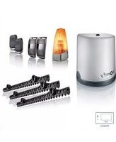
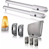
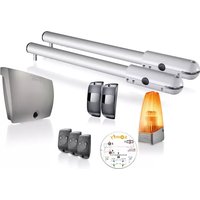
▶ Contents of the pack

| Mark | Designation | |
| a | Motor x 1 | |
| b Rack section33 cm x 20 mm | x 12 | |
| c Installation template x 1 | ||
| d 2-button remote control x 3 | ||
| e Set of photoelectric cells x 1 | ||
| f Flashing light x 1 | ||
| g Installation andoperating guide | x 1 | |
| Marl2ty | Designation | |
| h | Earth wire x 1 | |
| i Self-drilling screw x 4 | ||
| j Cable clamp x 1 | ||
| k Stud x 4 | ||
| l Plug | x 4 | |
| m | Somfy pencil | x 1 |
| n Cover screw | x 1 | |
| o O-ring | x 1 | |
| p Insulated round terminal | x 1 | |
| q Small flat washer | x 2 | |
| r | Star washer x 2 | |
| s Flat washer | x 8 | |
| t Nut | x 8 | |
▶ Space requirements

▶ Area of application
This product is intended for the motorisation of a sliding gate:
- with a max. length of 7 m and a max. weight of 500 kg
• in PVC, wood or metal
• for a detached house.
▶ General view of the installation

| Mark Designation | |
| A | Area lighting* |
| B | Flashing light |
| C | Antenna* |
| D | Safety edge* |
| E | Photoelectric cells |
| Mark Designation | |
| F | Closing end stop |
| G Opening end stop | |
| H Motor | |
| J Rack | |
*optional accessories
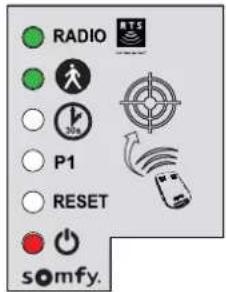
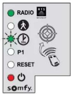
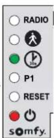
▶ Presentation of the control electronics

| Mark | Designation | Function | |
| A | Button [4X27] | Self-learning launchReactivation of the control electronics | |
| B RADIO indicator light | Lights up each time the control electronics receive a radio command | ||
| C Indicator light | Lights up during activation/deactivation of the pedestrian opening | ||
| D Indicator light [4X40] | On automatic closure of the gate is activated. | ||
| OFF automatic closure of the gate is not activated. | |||
| Flashing the "automatic closure" parameter is selected | |||
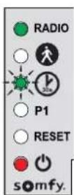
| E Indicator light P1 | OFF the gate operates at standard speed | ||
| Slowly flashing the gate operates at slow speed | |||
| Flashing the gate "speed" parameter is selected | |||
| F RESET indicator light | On the settings alone or the settings and the radio control points are deleted | ||
| Flashing the settings and radio control points deletion function is selected | |||
| G Indicator light | On the motor functions correctly - the control electronics are reactivated | ||
| OFF the motor functions correctly - the control electronics are on standby | |||
| Flashing see diagnostic page 32 | |||
Prerequisites for installation
▶ Stop blocks on the ground
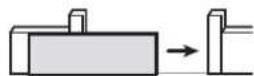
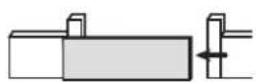
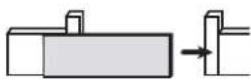
The gate travel must be defined by end stops firmly fixed in the ground.

▶ Positioning the motor

Electrical pre-equipment
Cables required
- Power supply: 3 x 1.5 mm 2 cable or 3 x 2.5 mm 2 for outdoor use (type H07RN-F minimum)
- Linking of cells: 2 × 0.75 mm2 cable
• Other accessories: see page 6
Cable feed
• Underground cables must be equipped with a protective sheath with a sufficient diameter to contain all the cables.
- Fit a 230 V electrical input as close as possible to the motor.

Provision must be made for the supply cable to be fed through according to the electrical standards in force in the country of use.

If a cable conduit cannot be made, use a cable grommet which will withstand the passage of vehicles (ref. 2400484).

▶ Cables required
i
The wiring details are provided in the "ACCESSORIES WIRING" section on pages 18 to 21.

i
To connect several accessories to the START terminal, a wire with a 0.3 mm2 cross section may be used (example: telephone cable) instead of wire with a cross section of 0.75 mm2 .
▶ Concrete base

The concrete base on which the motor will be installed must comply with the dimensions indicated on the diagram below.

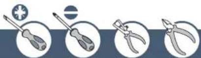
▶ Tools require for installation (not provided)

▶ Screws etc. required for installation of the rack and pinion (not provided) This information is provided for information purposes.
| Screws etc.required | Tools required Drilling diameter | ||
| IRON ORALUMINIUM GATE | Self-drilling hex-headscrew for metal of typeST 6.3 x 30 mm+ washer | Socket wrench no.10 | 5 mm with a drill for steel |
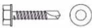 |  | ||
| PVC GATE | PVC is tool fragile to fasten the rack and pinion directly.PVC gates generally have an aluminium or metallic brace or a steel core(see the line above).If a PVC gate does not have a brace: fasten a metallic brace to the gate where the rack and pinion will be fastened. | ||
| WOODEN GATE | Wood screws, diameter6 x 40 mm minimum +washer | Socket wrench no.10 | Make a starter hole with a wood drill, diameter2.5 mm or wood auger. |
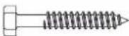 |  | ||
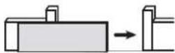
1.1 Unlock the motor
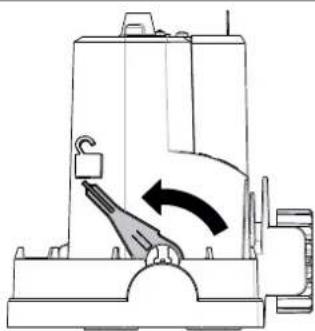
Position the motor's handle

The pinion is freed.
The motor is unlocked.
1.2 Installing the motor
▶ Fastening the motor to the ground
1

- Position the installation template 📄 on the ground and drill 4 holes using a drill bit (∅ 12 mm) suitable for the type of ground.

- Insert the plugs. Tighten the studs.
- Tighten 4 nuts and 4 washers.
- Remove the motor cover.
- Position the motor on the studs: ensure that
the bracket (base of the motor) is no more than 25 mm above the ground. The recommended space is between 20 and 25 mm.
- Once the motor is positioned at the right height in relation to the ground, fix it in place using the 4 washers and 4 nuts.

3
- Position the pre-drilled grommet in the opening provided for the cable feed.

Check that the motor is level.
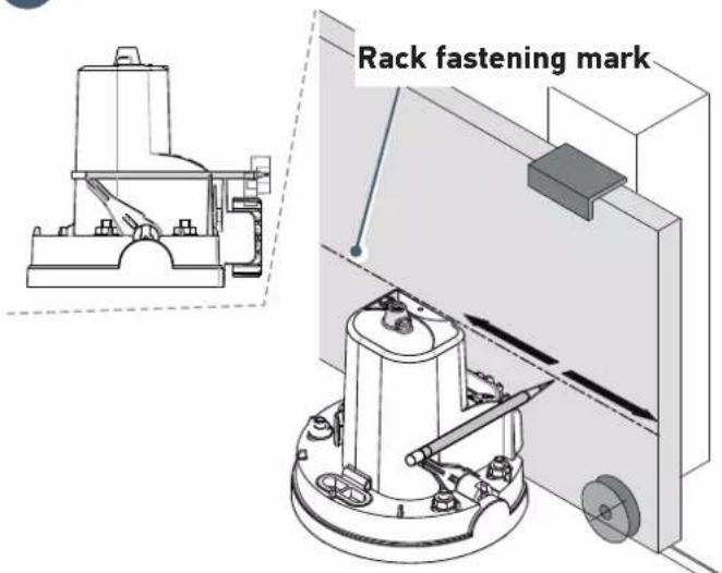
▶ Fastening the rack and pinion

!
• The rack and pinion must be fastened to the gate brace.
- Use suitable screws for the material of your gate (see page 8).
- Never lubricate the motor rack and pinion.
i
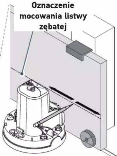
- By aligning the top of the rack with the line drawn in pencil, the required 2 mm clearance between the rack and pinion is obtained.
- If the fastening points are too close to the edge of the brace: fasten the rack at the centre of the oblong holes.

1
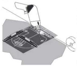
- Open the gate completely.
- Use the pencil provided to mark the position of the rack.
- Open the gate completely.
- Use the pencil provided to mark the position of the rack.
- Open the gate completely.
- Use the pencil provided to mark the position of the rack.
- Open the gate completely.
- Use the pencil provided to mark the position of the rack.
- Open the gate completely.
- Use the pencil provided to mark the position of the rack.
- Open the gate completely.
- Use the pencil provided to mark the position of the rack.
- Open the gate completely.
- Use the pencil provided to mark the position of the rack.
- Open the gate completely.
- Use the pencil provided to mark the position of the rack.
- Open the gate completely.
- Use the pencil provided to mark the position of the rack.
- Open the gate completely.
- Use the pencil provided to mark the position of the rack.
- Open the gate completely.
- Use the pencil provided to mark the position of the rack.
- Open the gate completely.
- Use the pencil provided to mark the position of the rack.
- Open the gate completely.
- Use the pencil provided to mark the position of the rack.
- Open the gate completely.
- Use the pencil provided to mark the position of the rack.
i
If the pencil makes a mark above the brace, the rack provided us not suitable for your gate. A low-fastening rack (ref. 2401294) must be used. Please contact Somfy.
- With one hand, hold the pencil in the notches provided on the motor and with the other hand, slide the gate to mark the fastening height of the rack.

- Position the rack by aligning the top of the rack with the line drawn in pencil.
- Fasten the first element of the rack at the top of the oblong holes, beginning at the left-hand side of the gate.
• Install and fasten the other items in the same way, interlocking them with the others.
1.3 Checking the installation of the motor
Check that:
- the motor is level.
• the gate runs correctly,
• the pinion is correctly driven. - the 2 mm clearance between the rack and pinion does not vary significantly.
If these conditions are not satisfied, adjust the height of the rack.
Once all these checks have been completed, tighten the nuts to fasten the motor permanently.
1.4 Locking the motor

Never lock the motor when the gate is moving as this may damage the motorisation

Push the motor handle towards the gate.
The motor is locked.
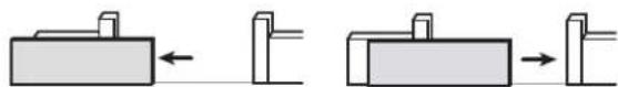
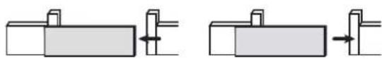
1.5 Wiring the motor


For your safety, these operations must be carried out with the power supply switched off.

The motor is wired as standard for installation to the left of the gate
To install the motor to the right of the gate, switch the wires connected to terminals 10 and 11 of the control electronics (green M1 label).
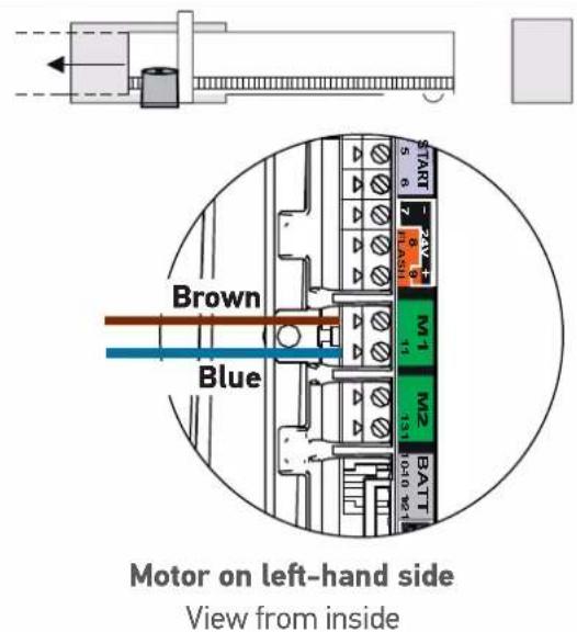
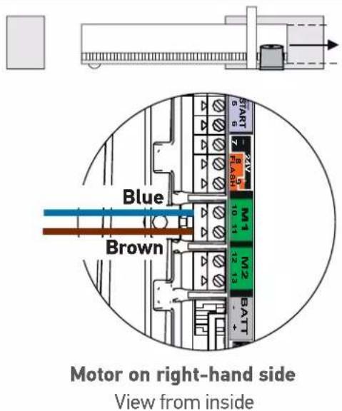

Connect nothing to terminal M2.
1.6 Connecting to the 230V power supply
!
- For your safety, these operations must be carried out with the power supply switched off.
- Use a 3 x 1.5 mm 2 cable or 3 x 2.5 mm 2 for outdoor use (type H07RN-F minimum).
- The cable clamp supplied must be used. For all low-voltage cables, ensure that they can withstand traction of 100 N. Check that the conductors have not moved when this traction has been applied.
- Strip the wire over a distance of 150 mm.
- Overlap the live and neutral wires at 100 mm.
- Strip the 3 wires over a distance of 8 mm.
- Crimp the terminal provided on the earth wire (yellow and green).
- Connect the wires as shown in the table:

| Wire colour | Type Terminal Comments | ||
| Blue Neutral | 17 | ||
| Brown / black / red | Live 16 | ||
| Yellow and green | Earth |  | Tighten a flat washer q, the power supply earth terminal crimped in step 4 and a star washer r using a screw i. |

- Tighten the cable clamp supplied.

For a 3x1.5 mm 2 cable For a 3x2.5 mm 2 cable
1.7 Earthing the control electronics
- Connect the earth wire supplied in the top right of the control electronics.
- Tighten a flat washer q, the earth wire terminal h and a star washer rising a screw i to the top of the motor.

1.8 Position of the control electronics antenna
Position the antenna on top of the motor.

2.1 Switching the installation on
- The 0 indicator flashes (twice).
The motor is switched on and awaiting self-learning.
- If the indicator light does not come on or the number of flashes is not as expected: see diagnostic page 32.
2.2 Gate travel self-learning
Prerequisite - before starting self-learning, check that:
- The installation is switched on: the indicator light ⏻ flashes (twice).
- The gate is at its mid-point. - The motor is locked.
Press the button on the control electronics.
- The gate opens, closes, opens partially and closes again.
• The indicator light is lit constantly.
Self-learning has been successfully completed and the motor is operational.

If the indicator light ⏻ flashes (twice), begin the self-learning process again.
The gate must be closed once self-learning is complete.

If the gate is open, see the IMPORTANT box below.

IMPORTANT
If the gate is open once self-learning is complete:
- Clear the settings (see page 31).
- Switch the motor off.
- Unlock the motor.
- Position the gate at its mid-point.
- Lock the motor.
- Switch the motor on.
-
Starting the self-learning process again.
-
switch the wires connected to terminals 10 and 11 (green M1 label) of the control electronics (see "Motor wiring", page 12).

During the self-learning process, pressing button 1 on the remote control or the ⏻ button on the control electronics causes the gate and the self-learning process to stop.
2.3 Standby / reactivation of the control electronics
i
Once the self-learning process has been completed, the electronics automatically switch to standby after 5 minutes of inactivity to save energy.
In standby mode, all indicator lights are switched off.
To check if the motor is switched on or to check/modify the parameter setting, press the ⏻ button for 2 seconds to reactivate the electronics.
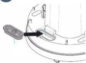
2.4 Plugging the openings

i
You are strongly advised to plug all the openings to avoid short circuits caused by insects.
Once all the cables have been fed through, plug the openings (oblong holes, cable feed openings) using silicone.
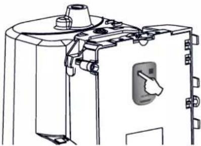
2.5 Lifting the cover

-
Place the cover on the motor bracket (base).
-
Insert the seal o to ensure the motor and cover screw n are watertight.
-
Fasten the cover.
2.6 Fully opening and closing the gate
i
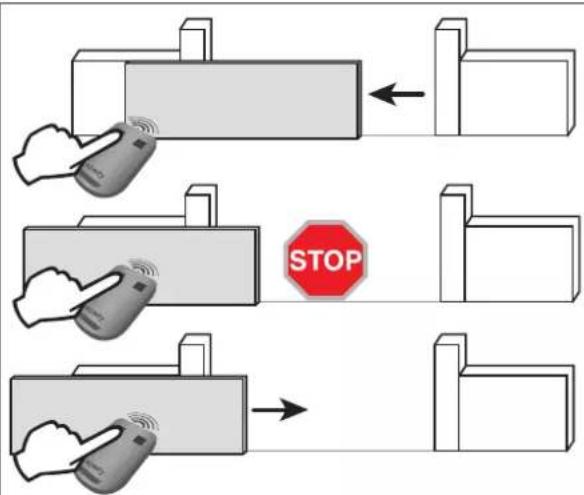
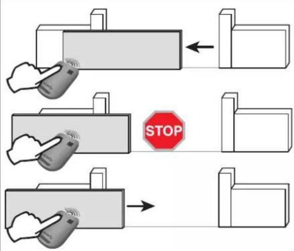
The remote controls supplied with the kit are already memorised and programmed so that button 1 on the remote controls activates full opening of the gate.


- Gate closed: press button 1 on the remote control to open the gate to the full.
- Gate moving: press button 1 on the remote control to stop the gate.
- Gate open: press button 1 on the remote control to close the gate.
2.7 Obstacle detection
If an obstacle is detected (abnormal force on the motorisation):
- When the gate is opening: the gate will stop.
- When the gate is closing: the gate will stop and reopen.
3 WIRING THE ACCESSORIES

For your safety, these operations must be carried out with the power supply switched off.

You are advised to perform auto-programming of the gate travel before connecting the accessories (photoelectric cells, flashing light, etc.)
3.1 Photoelectric cells


It is not possible to connect a second set of photoelectric cells on this motorisation.

or

▶ Installation
After wiring the photoelectric cells:
- switch the motor on again,
- start a gate opening or closing procedure.
The photoelectric cells are recognised by the control electronics once this movement is complete.
▶ Operation with photoelectric cells
If the cells are blocked when closing the gate, the gate will stop and reopen. If the gate is open and the cells are blocked, the gate will not close.
▶ In the event of photoelectric cell disconnection
After disconnection of the photoelectric cells, switch the motor on again then perform the procedure "Deactivating automatic closing" on page 24.
3.2 Flashing light


10 W - 24 V bulb MAXIMUM - use of a bulb with power greater than 10 W - 24 V can cause motorisation malfunctions.

▶ Operation of the flashing light
The light flashes while the gate is moving.
3.3 Battery (optional)

This accessory is not compatible with solar power.

To optimise the service life of the battery, cut the electrical power to the gate at least 3 times a year and run a few cycles using the battery.

The backup battery ensures the operation of the gate in the event of an electrical power failure. The indicator light ⏻ flashes (1 pulse) when the motor is battery-operated.
![graph LR A["Packet Packet"] --> B["BATT - +"] B --> C["Component Block"] C --> D["Output"]](/content/2026/04/659950/images/4b832960d730a9ae7ed8a36f2d7771344e63a7aadc79451441802917a4a35979.jpg)
Battery specifications:
- Battery life: 10 continuous cycles or 24 hours on a gate in perfect condition.
- Optimum charge time before using the battery: 48 hours
• Service life: 3 years.

To increase the operation time of the battery during use, the wired controls are deactivated and the gate can only be controlled using the remote controls and the radio control points.
3.4 Offset antenna (optional)


i
The antenna wire can be replaced with an offset antenna with a greater range.
This is placed on top of the pillar and must be clearly accessible.
The offset antenna is connected to terminals 1 and 2 of the electronics unit (blue "ANT" label):
• the wire core to terminal 1
• the ground strap to terminal 2
3.5 Video door phone (optional)

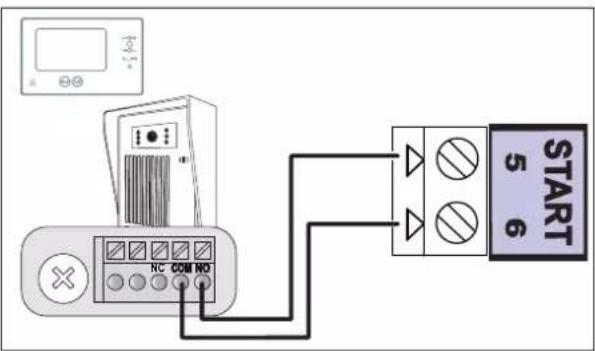
!
This accessory is not compatible with solar power.
!
Only connect one non-powered dry contact.
3.6 Key lock (optional)

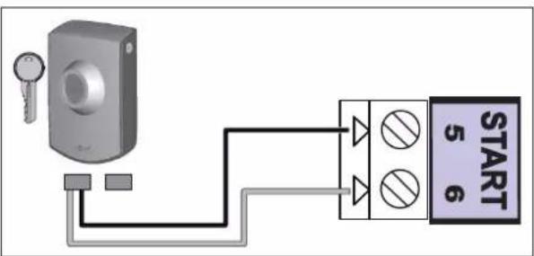
!
This accessory is not compatible with solar power.
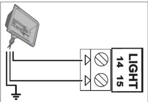
3.7 Area lighting (optional)


This accessory is not compatible with solar power.
Only use halogen or incandescent bulbs for area lighting, 500 W maximum.
3.8 Solar power (optional)

Never connect your motor to a 230 V power supply when it is connected to a solar power supply, as this may damage the motor's electronics unit.

When the motor is running on the solar feed:
- only the remote controls and radio control points can be used to control the gate (wired controls are deactivated),
- the wired safety accessories (photoelectric cells, flashing light) remain active.
4.1 Pedestrian opening
▶ Pedestrian opening operation
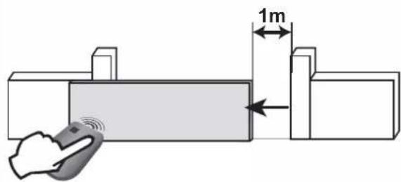

Pressing the remote control button programmed to open the pedestrian opening causes the date to open about 1 metre. Pressing it again causes the gate to close.
▶ Activating the pedestrian opening
i
Button 1 on 2- or 4-button remote controls cannot be programmed to control pedestrian opening. See "Programming the remote controls", pages 27-29, for more information.
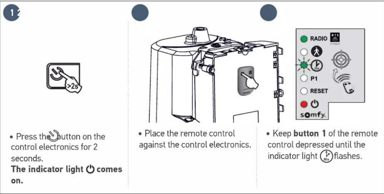
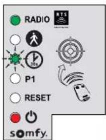
1

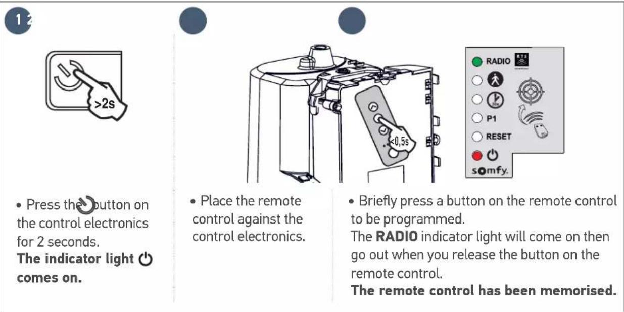
- Press on the button of the control electronics for 2 seconds. The indicator light ⏻ comes on.
2
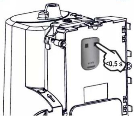
- Place the remote control against the control electronics.
3
- Press button 2 on the remote control.
The "RADIO" and 🙏 indicator lights come on then go out. The pedestrian opening is activated on this button.
i
Move away from the control electronics to test the pedestrian opening.
▶ Deactivating the pedestrian opening
Repeat the "Activate pedestrian opening" procedure using the button for which the pedestrian opening must be deactivated. The indicator light ⚙ comes on then goes out. The pedestrian opening is deactivated on this button.
4.2 Automatic closing
▶ Automatic closure operation
Press button 1 on the remote control to open the gate.
The gate closes again after 30 seconds or 5 seconds if the photoelectric cells detect a passage.
The automatic closing can be interrupted by pressing button 1 on the remote control. To then close the gate, press button 1 on the remote control again.
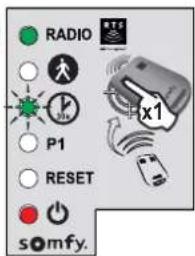
▶ Activating automatic closing

The automatic closing can only be activated if the photoelectric cells are connected and recognised by the motor's control electronics.


- Press on the button of the control electronics for 2 seconds. The indicator light ⏻ comes on.


- Place the remote control against the control electronics.
- Keep button 1 of the remote control depressed until the indicator light ⏻ flashes.


- Keep button 2 on the remote control depressed until the indicator light ⏻ goes out and is then lit constantly.


- When you release button 2, the indicator light flashes; press button 1 on the remote control 3 times
The indicator light ⏻ 30° remains lit. Automatic closing is activated.
▶ Deactivating automatic closing
![graph LR A["45"] --> B["• Press button 2 on the remote control. The indicator light flashes."] B --> C["• Press button 1 on the remote control 3 times."] C --> D["The indicator light is off. Automatic closing is deactivated."]](/content/2026/04/659950/images/e3d3d17771579d3ecf5d780d4d16196919ed58176c5e3f3bd8b346933ac33734.jpg)
4.3 Gate speed

A speed not adapted to the weight of the gate could cause serious injury to users, for example by being crushed by the gate. To meet the requirements of standard EN 12453, it is essential to comply with the field of application constraints.

By default, the gate operates at standard speed
▶ Field of application
Set the gate speed in accordance with the table below:
| Gate weight Standard speed Slow speed | ||
| 0 to <100 kg |  |  |
| 100 to <200 kg | [OKWZ] |  |
| 200 to <300 kg |  + safety edge* + safety edge* | [CH30] |
| 300 to <400 kg | [2OH5] + safety edge* |  |
| 400 to 500 kg |  |  + safety edge* + safety edge* |
- safety edge*
*Installation of a passive safety edge (ref. 9019612) mandatory on the gate.
▶ Setting slow speed

▶ Setting slow speed (continued)
6
![graph LR A["Radio"] --> B["P1"] B --> C["RESET"] C --> D["somfy."] E["Radio"] --> F["P1"] F --> G["RESET"] G --> H["somfy."] I["RADIO"] --> J["P1"] J --> K["RESET"] K --> L["somfy."]](/content/2026/04/659950/images/010419308ee129b5ff84e7fff3fc2c4a09962261ea4e17099987f1de3d2fb597.jpg)
- Keep button 2 depressed until the indicator light P1 flashes slowly. Slow speed is selected.
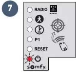
7
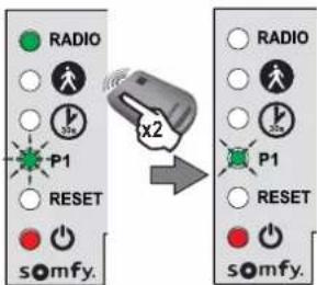
- Press button 1 on the remote control twice. Indicator light P1 flashes slowly. Slow speed is selected.
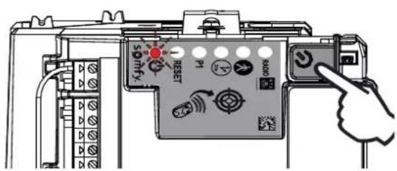
▶ Returning to standard speed
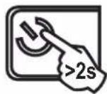
- Press the button on the control electronics for 2 seconds.
The indicator light ⏻ comes on.
2
- Place the remote control against the control electronics.
3
- Keep button 1 of the remote control depressed until the indicator light ⏻ flashes.
4
- Press button 1 on the remote control once. Indicator light P1 flashes.
5
![graph LR A["Input Signal"] --> B["Signal State"] B --> C["Response Signal"] C --> D["Device Interaction"] D --> E["Output Signal"]](/content/2026/04/659950/images/83a3c720382a30415a6582315725a7cd689f7d4fc5af075b6fa76c7b8dca0541.jpg)
- Press button 2 on the remote control once. Indicator light P1 goes out for 5 seconds then flashes.
6
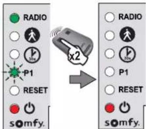
- Press button 1 on the remote control twice. Indicator light P1 is off. Standard speed is selected.
5.1 Presenting the remote controls

2-button remote control

4-button remote control
Depending on the choice of settings, Somfy RTS remote controls can control:
• full opening of the gate
• pedestrian opening of the gate
- another Somfy RTS device (example: garage door motor, roller shutter, etc.)

The remote controls supplied with the kit are already memorised and programmed so that button 1 on the remote controls activates full opening of the gate.
i
You can memorise up to 16 control points for a motor (remote controls, other radio control points). If you memorise a 17th control point, the first point memorised will automatically be deleted.
i
If you wish to programme a pedestrian opening, it must be programmed on the button following the one used to open the gate fully (e.g.: full opening controlled by button 2, pedestrian opening controlled by button 3).
It is not possible to programme pedestrian opening on button 1 of the remote controls.
▶ Possibilities for programming the 2-button remote control
| Button 1 | Button 2 | |
| Possibility 1 | Complete opening Pedestrian opening | or otherSomfy RTS automatism |
| Possibility 2 Another Somfy RTS device Complete opening | ||
▶ Possibilities for programming the 4-button remote control
| Button 1 | Button 2 | Button 3 | Button 4 | |
| Possibility 1 | Complete opening Pedestrian opening or other Somfy RTS automatism | Another Somfy RTS automatism | Another Somfy RTS automatism | |
| Possibility 2 | Another Somfy RTS automatism | Complete opening Pedestrian opening or other Somfy RTS automatism | Another Somfy RTS automatism | |
| Possibility 3 | Another Somfy RTS automatism | Another Somfy RTS automatism | Complete opening Pedestrian opening or other Somfy RTS automatism | |
| Possibility 4 | Another Somfy RTS automatism | Another Somfy RTS automatism | Another Somfy RTS automatism | Complete opening |
▶ Using a 3-button remote control

- To open the gate completely, press the "Up" button on the remote control.
- To stop the gate while it is moving, press the central button on the remote control.
- To close the gate, press the "Down" button on the remote control.
i
The 3-button remote control cannot be used to change the motor settings.
5.2 Adding a remote control
▶ 2 or 4-button remote control

- Press the button on the control electronics for 2 seconds. The indicator light comes on.
- Place the new remote control to be programmed against the control electronics.
- Briefly press the button on the remote control to be programmed. The RADIO indicator light will come on then go out when you release the button on the remote control.
Complete opening is programmed on this button.
▶ 3-button remote control
- Press the button on the control electronics for 2 seconds. The indicator light comes on.
- Place the remote control against the control electronics.
- Briefly press a button on the remote control to be programmed.
The RADIO indicator light will come on then go out when you release the button on the remote control.
The remote control has been memorised.
5.3 Deleting a remote control
See "Clearing the settings" page 31.

The motorisation must be disconnected from any power supply during cleaning, during maintenance and when parts are replaced.
6.1 Assistance
Despite the care taken in the design of our products and the creation of our guides, you may encounter difficulties during the installation of your automatic control device or have some unanswered questions. Do not hesitate to contact us; our specialists are on hand to answer all your questions.
6.2 Replacing the remote control battery
The service life of the battery is generally 2 years.
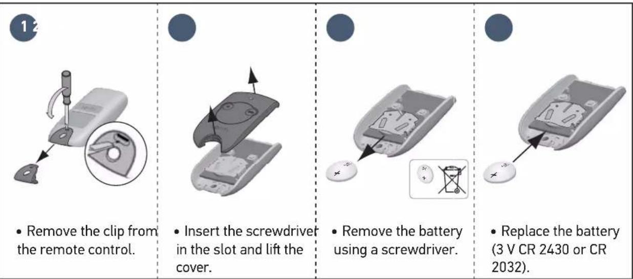
- Remove the clip from the remote control.
- Insert the screwdriver in the slot and lift the cover.
- Remove the battery using a screwdriver.
- Replace the battery (3 V CR 2430 or CR 2032).
6.3 Clear the settings
When should I delete the settings?
- After auto-programming, if you change the position stop, if you change the motor wiring or if you add a safety edge to the gate.
- If the gate opens at random due to normal wear of the gate.
12 |  |  |  | 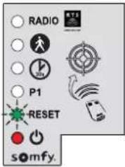 |
| • Press the button on the control electronics for 2 seconds. The indicator light comes on. | • Place the memorised remote control against the control electronics. | • Keep button 1 of the remote control depressed until the indicator light flashes. | • Press button 1 on the remote control twice. | The "RESET" indicator light flashes. |
| To clear the settings* | To clear the settings* and the memorised remote controls/control points | |||
 | • Keep button 2 of the remote control depressed until the "RESET" indicator light comes on. |  | • Keep button 2 of the remote control depressed until the all the indicator lights come on. | |
 | The indicator light flashes twice (see page 15 to run a self-learning procedure). | |||
To clear the settings*
*Gate travel, deactivation of the settings, ...
6.4 Diagnostics
| Diagnostics Repairs | ||
| The motor does not respond to commands from the remote control | The remote control range is reduced | Check the remote control battery ("Replacing the remote control battery", see page 30).Check the antenna of the electronics unit (wiring, position, see page 14).Check that there are no outside elements that may be interfering with the radio signal (electric pylon, metal reinforced walls, etc.). If this is the case, fit an offset antenna. |
| Non-memorised remote control | Memorise the remote control (see page 29). | |
| Motor unlocked Lock the motor. | ||
| The indicator light on the electronics unit is off | The electronics unit is on standby | Press for 2 seconds to reactivate the electronics unit. |
| No power supply to the control electronics | Check the mains power supply.Check the power supply cable. | |
| The indicator light of the electronics unit is flashing: | ||
| 1 flash Operation using the backup battery | Check the mains power supply. | |
| 2 flashes Motor waiting for gate travel to be programmed | Start self-learning procedure (see page 15). | |
| 3 flashes | Faulty photoelectric cells | Check that there is nothing obstructing the cells.Check cell alignment.Check the cell wiring (see page 18).If the photoelectric cells are disconnected, deactivate automatic closing (page 24). |
| 4 flashes Short circuit of electronic unit "START" output (terminals 5-6) | Check the accessories connected to the electronic unit's "START" output. | |
| 5 flashes Motor thermal protection device activated | Allow the motor to cool down for several minutes. | |
| 6 flashes Short circuit of electronics unit's "BUS" output (terminals 3-4) | Check the accessories connected to the electronic unit's "BUS" output. | |
| Short circuit of electronics unit's "24 V output" (terminals 7-9) | ||
| Short circuit of the electronics unit's "flashing light" (terminals 8-9) | ||
| Motor short circuit Check the motor wiring (see page 12). | ||
| 7 flashes Electronic fault Contact Somfy assistance. | ||
| Power supply 230 V-50 Hz / 24 V (with solar power) | ||
| Motor type 24 V | ||
| Motor output 120 W | ||
| Max. power consumed(with area lighting) | 600 W | |
| Standby consumption 3.5 W | ||
| Maximum frequency of movements per day 20 cycles per day10 cycles per day using solar power | ||
| Opening time 16 s for a gate of 150 kg/3m | ||
| Automatic obstacle detection Compliant with standard EN 12 453 | ||
| Operating temperature -20°C to +60°C | ||
| Thermal protection Yes | ||
| Protection rating IP 44 | ||
| Integrated radio receiver Yes | ||
| Remote controls | ||
| • Radio frequency | 433.42 MHz, < 10 mW | |
| • Range in field of use | ~30 m | |
| • Storage quantity | 16 | |
| Possible connections: | ||
| • Flashing light output | Flashing, 24 V, 10 W maximum | |
| • Lighting output | 500 W max. with 230 V (halogen or incandescent only) | |
| • Accessories supply output | 24 Vdc / 15 W max. | |
| • Backup battery input | Yes | |
| • Photoelectric cell input | Yes | |
| • Dry contact control input | Yes (does not work with battery or solar power) | |
Inhalt
1

- Legen Sie die
Montageschablone
!
!


| Nummer | Omschrijving |
| A | Verlicht gebied* |
| B | Knipperlicht |
| C | Antenne* |
| D | Contactstrip* |
| E | Foto-elektrische cellen |
1
!
!
!
4.1 Voetgangersopening
The image is too blurry to recognize any text content.

1

!
!
The image is too blurry to recognize any text content.

Kontrolka "RESET" miga.
Somfy Romania S.R.L.
(+4) 0374 494 418
www.somfy.ro
- SOMMAIRE
- I
- PREREQUISITES FOR INSTALLATION 5
- 1 INSTALLATION 9
- 2 COMMISSIONING AND STANDARD USE 15
- 3 WIRING THE ACCESSORIES 18
- 4 ADVANCED PARAMETER SETTINGS 22
- 5 PROGRAMMING THE REMOTE CONTROLS
- 6 REPAIRS 30
- 7 TECHNICAL DATA 33
- PRODUCT PRESENTATION
- AREA OF APPLICATION
- PREREQUISITES FOR INSTALLATION
- CABLES REQUIRED
- CABLE FEED
- 1.1 UNLOCK THE MOTOR
- 1.2 INSTALLING THE MOTOR
- 1
- 1.3 CHECKING THE INSTALLATION OF THE MOTOR
- CHECK THAT
- 1.4 LOCKING THE MOTOR
- 1.5 WIRING THE MOTOR
- 1.6 CONNECTING TO THE 230V POWER SUPPLY
- 1.7 EARTHING THE CONTROL ELECTRONICS
- 1.8 POSITION OF THE CONTROL ELECTRONICS ANTENNA
- 2.1 SWITCHING THE INSTALLATION ON
- 2.2 GATE TRAVEL SELF-LEARNING
- PREREQUISITE - BEFORE STARTING SELF-LEARNING, CHECK THAT
- IMPORTANT
- IF THE GATE IS OPEN ONCE SELF-LEARNING IS COMPLETE
- 2.3 STANDBY / REACTIVATION OF THE CONTROL ELECTRONICS
- 2.4 PLUGGING THE OPENINGS
- 2.5 LIFTING THE COVER
- 2.6 FULLY OPENING AND CLOSING THE GATE
- 2.7 OBSTACLE DETECTION
- 3 WIRING THE ACCESSORIES
- 3.1 PHOTOELECTRIC CELLS
- INSTALLATION
- OPERATION WITH PHOTOELECTRIC CELLS
- IN THE EVENT OF PHOTOELECTRIC CELL DISCONNECTION
- 3.2 FLASHING LIGHT
- 3.3 BATTERY (OPTIONAL)
- BATTERY SPECIFICATIONS
- 3.4 OFFSET ANTENNA (OPTIONAL)
- 3.5 VIDEO DOOR PHONE (OPTIONAL)
- 3.6 KEY LOCK (OPTIONAL)
- 3.7 AREA LIGHTING (OPTIONAL)
- 3.8 SOLAR POWER (OPTIONAL)
- WHEN THE MOTOR IS RUNNING ON THE SOLAR FEED
- 4.1 PEDESTRIAN OPENING
- 4.2 AUTOMATIC CLOSING
- AUTOMATIC CLOSURE OPERATION
- ACTIVATING AUTOMATIC CLOSING
- 4.3 GATE SPEED
- FIELD OF APPLICATION
- SETTING SLOW SPEED
- SETTING SLOW SPEED (CONTINUED)
- RETURNING TO STANDARD SPEED
- 5.1 PRESENTING THE REMOTE CONTROLS
- 5.2 ADDING A REMOTE CONTROL
- 2 OR 4-BUTTON REMOTE CONTROL
- 3-BUTTON REMOTE CONTROL
- 5.3 DELETING A REMOTE CONTROL
- 6.1 ASSISTANCE
- 6.2 REPLACING THE REMOTE CONTROL BATTERY
- 6.3 CLEAR THE SETTINGS
- WHEN SHOULD I DELETE THE SETTINGS
- TO CLEAR THE SETTINGS
- 6.4 DIAGNOSTICS
- INHALT
- 4.1 VOETGANGERSOPENING
- THE IMAGE IS TOO BLURRY TO RECOGNIZE ANY TEXT CONTENT
- SOMFY ROMANIA S.R.L
Brand : SOMFY
Model : Freevia Line
Category : Garage door opener