
SGS Line - Garage door opener SOMFY - Free user manual and instructions
Find the device manual for free SGS Line SOMFY in PDF.
| Brand | Somfy |
| Model | SGS Line |
| Product type | Swing garage door operator |
| Usage | Residential |
| Power supply | 230 V / 50 Hz (or 24 V solar) |
| Motor power | 120 W |
| Maximum power consumption | 600 W (with zone lighting) |
| Standby consumption | 3 W (without accessories) |
| Maximum weight per leaf | 200 kg |
| Maximum leaf height | 2 m |
| Leaf width (min/max) | 1.25 m / 2 m |
| Opening time at 90° | 20 s minimum |
| Obstacle detection | Yes (compliant with EN 12453) |
| Operating temperature | -20 °C to +60 °C |
| Protection rating | IP44 |
| Integrated radio receiver | 433.42 MHz, range ~30 m |
| Memory capacity | 16 control points (remote controls, etc.) |
| Remote controls supplied | 2-button or 4-button (depending on pack) |
| Main functions | Full opening, pedestrian opening, automatic closing, stop |
| Optional accessories | Backup battery, flashing light, photocells, remote antenna, video door phone, key switch, zone lighting |
| Maintenance | Monthly check of wear and obstacle detection; clean cells; disconnect power before maintenance |
| Safety | Manual release, integrated opening stops, thermal protection, mandatory all-pole disconnection |
| Standards | CE (Machinery Directive 2006/42/EC, Radio Directive 2014/53/EU) |
| Spare parts and repairability | Use exclusively original parts; any modification must be approved by Somfy |
Frequently Asked Questions - SGS Line SOMFY
User questions about SGS Line SOMFY
0 question about this device. Answer the ones you know or ask your own.
Ask a new question about this device
Download the instructions for your Garage door opener in PDF format for free! Find your manual SGS Line - SOMFY and take your electronic device back in hand. On this page are published all the documents necessary for the use of your device. SGS Line by SOMFY.
USER MANUAL SGS Line SOMFY
natural_image
3D rendered image of a metallic mechanical device with cylindrical components and a separate bracket, displayed against a reflective background (no text or symbols)Sommaire
natural_image
Diagram of a two-level mechanical or electrical device labeled 'Zone 5' with no visible text or symbols on the device itself.natural_image
Illustration of a hand pressing a corner component (no text or symbols)

Solution :
natural_image
Silhouette of a person standing inside a door with a vertical pipe inserted (no text or symbols)
Solution :
natural_image
Line drawing of two identical door structures with vertical slats, no text or symbols present
natural_image
Simple line drawing of a doorway with a cross symbol at the center (no text or labels)Renforts
natural_image
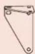
Four identical line drawings of a metal bracket with mounting holes, labeled 'ou' (no text or symbols on the brackets themselves)
natural_image
Technical line drawing of a mechanical clamp or bracket assembly (no text or symbols)natural_image
Diagram showing a tool interacting with a wire and a spring, with no visible text or symbolsnatural_image
Technical line drawing of a mechanical bracket or clamp assembly (no text or symbols)natural_image
Technical line drawing of a mechanical component with a red arrow indicating direction (no text or symbols)natural_image
Technical line drawing of a mechanical clamp or bracket assembly (no text or symbols)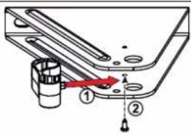
natural_image
Diagram of a balanced lever system with two supports and directional arrows indicating force or motion (no text or labels)Fermer le portail.
natural_image
Technical line drawing of a mechanical assembly with no visible text or symbolsnatural_image
Technical line drawing of a mechanical assembly with a tool inserted into a cylindrical component (no text or symbols)natural_image
Technical line drawing of a mechanical component with a rod inserted, showing alignment lines (no text or symbols)natural_image
Illustration of a handheld tool with a string and two dots, no text or symbols presentnatural_image
Technical line drawing of a mechanical component with mounting holes and a central housing (no text or symbols)▶ Vérifier la position de l'antenne
natural_image
Technical line drawing of a mechanical assembly with no visible text or symbols2
flowchart
graph TD
    A["Sensor input"] --> B["Stop Button"]
    C["Hand gesture"] --> D["Stop Button"]
    style A fill:#f9f,stroke:#333
    style C fill:#f9f,stroke:#333
    style B fill:#ccf,stroke:#333
    style D fill:#ccf,stroke:#333
    note right of B: Arrow indicates leftward shift from left to right.
    note right of D: STOP (Stop Button)
natural_image
Technical diagram showing mechanical assembly with a bracket and a close-up of a mechanical component (no text or symbols)natural_image
Technical diagram showing mechanical assembly with two views: top shows linear rail system with adjustment knob, bottom shows mechanical component with red ribbon (no text or symbols)natural_image
Diagram showing a device with two panels and directional arrows indicating rotation (no text or symbols)
flowchart
graph LR
    A["Speaker"] --> B["Document"]
    B --> C["-->"]
    C --> D["Document"]


natural_image
Diagram showing a hand holding a sensor with signal waves, and two rods with arrows indicating rotation (no text or symbols)cs
natural_image
Diagram of a mechanical device with internal components and directional arrows indicating flow or movement (no text or symbols present)
natural_image
Technical line drawing of a mechanical device with internal components (no text or symbols)natural_image
Simple diagram showing a solar panel connected to a battery via a switch (no text or symbols)flowchart
graph LR
    A["Start"] --> B["Step 1: Radio icon with P1 clock and symbol"]
    B --> C["Step 2: Radio icon with P1 clock and symbol"]
    C --> D["Step 3: Radio icon with P1 clock and symbol"]
    D --> E["End"]
The image is too blurry to recognize any text content.
natural_image
Mechanical device with a lever and bracket, showing a close-up of a tool interacting with a component (no text or symbols visible)natural_image
3D diagram of a device with an open lid and internal components, showing directional arrows (no text or symbols)natural_image
Close-up of a computer mouse with a button and an inset showing a battery symbol (no text or labels)natural_image
Close-up of a computer mouse with a cursor pointing to the interior (no text or symbols visible)flowchart
graph LR
    A["Radio"] --> B["RESET"]
    B --> C["Comedy"]
    D["Comedy"] --> E["Comedy"]
    F["Comedy"] --> G["Comedy"]
Safety instructions 2
- Important information 2
- Condition of the gate to be motorised 2
- Electrical installation 2
- Cable feed 3
- Safety instructions relating to installation of the motorisation 3
- Safety instructions relating to operation 3
- Safety instructions relating to maintenance 4
- About the batteries 4
- Recycling and disposal 4
-
Regulations
- Risk prevention 4
Product description 6
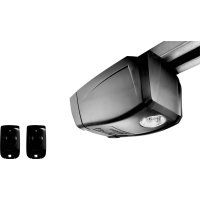
- Contents of the pack 6
- Product description 7
- Space requirements 7
- Field of application 7
- General view of the installation 8
- Presentation of the control electronics 9
Prerequisites for installation
- Pre-installation checks 9
- Electrical pre-equipment 10
- Cables required 10
- Tools required for installation (not provided) 11
- Hardware required for installation (not provided) 11
1 Installation
1.1 Measuring the dimensions 12
1.2 Fastening the pillar brackets 13
- Marking the AM and AH axes 13
- Drilling the pillars 13
- Securing the pillar mounting bracket 14
- Fitting the cylinder onto the mounting bracket 14
1.3 Securing the motors to the gate leaves 14
1.4 Installing the control unit 16
- Position of the control unit 16
- Installing the sealing strip 16
- Checking the position of the antenna 16
- Securing the control unit 16
1.5 Connecting the motors 18
1.6 Connecting to the power supply 18
2 Commissioning and standard use 19
2.1 Switching the installation on 19
2.2 Adjusting the opening stop 19
2.3 Gate travel auto-programming 20
2.4 Closing the control unit 21
2.5 Standby/Reactivating the control electronics 21
2.6 Fully opening and closing the gate 21
2.7 Obstacle detection 21
2.8 User training 21
3 Wiring the accessories 22
3.1 Photoelectric cells 22
3.2 Flashing light 22
3.3 Battery (optional) 22
3.4 Offset antenna (optional) 23
3.5 Video entry phone (optional) 23
3.6 Key lock (optional) 23
3.7 Area lighting (optional) 23
3.8 Solar power (option) 23
4 Advanced parameter settings 24
4.1 Pedestrian opening 24
- Pedestrian opening operation 24
- Activating the pedestrian opening 24
- Deactivating the pedestrian opening 24
4.2 Automatic closing 25
- Automatic closure operation 25
- Activating automatic closing 25
- Deactivating automatic closing 26
5 Programming the remote controls 27
5.1 Description of the remote controls 27
- Possibilities for programming the 2-button remote control 27
- Possibilities for programming the 4-button remote control 27
- Using a 3-button remote control 27
5.2 Adding a remote control 28
2- or 4-button remote control 28
- 3-button remote control 28
5.3 Deleting a remote control 28
6 Troubleshooting guide 29
6.1 Assistance 29
6.2 Replacing the remote control battery 29
6.3 Clearing the settings 30
6.4 Unlocking/locking the motors 30
6.5 Diagnostics 31
7 Technical data 32
> Safety instructions
This symbol indicates a danger, the different degrees of which are described below.

DANGER
Indicates a danger which may result in immediate death or serious injury.

WARNING
Indicates a danger which may result in death or serious injury.

PRECAUTION
Indicates a danger which may result in minor or moderate injury.
CAUTION
Indicates a danger which may result in damage to or destruction of the product.

WARNING
CAUTION - Important safety instructions For reasons of personal safety, it is important to follow all the instructions, as incorrect installation can lead to serious injury. Retain these instructions. The installer must train all users to ensure the motorisation is used in complete safety, in accordance with the operating manual. The instructions must be given to the end user.
▶ Important information
This product is a motorisation for a hinged gate on a residential property as defined in standard EN 60335-2-103, with which it is compliant. The main purpose of these instructions is to satisfy the requirements of the aforementioned standards and to ensure the safety of equipment and persons.

WARNING
Any use of this product outside the field of application described in this manual is prohibited (see "Field of application" paragraph in the manual). The use of any accessory or any component not recommended by Somfy is prohibited, on safety grounds. Somfy cannot be held liable for any damage resulting from failure to follow the instructions in this manual.
If in any doubt when installing the motorisation or to obtain additional information, consult the website www.somfy.com. The instructions may be modified if and when there is a change to the standards or to the motorisation.
▶ Condition of the gate to be motorised
Before installing the motorisation, check that:
- the gate is in good mechanical condition.
- the gate is stable regardless of its position.
- the structures supporting the gate allow the motorisation to be fixed securely. Strengthen these if necessary.
- the gate can be correctly opened and closed manually using a force of less than 150 N.
- the temperature range inscribed on the motorisation is suitable for the location.
CAUTION
Do not spray water onto the motorisation. Do not install the motorisation in an explosive environment.

WARNING
Ensure that any danger zones (crushing, cutting, trapping) between the driven part and the surrounding fixed elements caused by the opening movement of the driven part are avoided or indicated on the installation (see "Risk prevention").
Permanently affix the crushing warning labels near to any fixed control devices, and so that they are clearly visible to the user.
Electrical installation

DANGER
The installation of the power supply must comply with the standards in force in the country in which the motorisation is installed, and must be carried out by qualified personnel.

DANGER
The electric line must be exclusively reserved for the motorisation and equipped with protection, comprising:
• a 10 A fuse or breaker,
• a differential type device (30 mA).
An all-pole power supply cut-off device must be provided. The switches provided to ensure a cut-out of all poles on fixed appliances must be connected to the power supply terminals and there must be a separation between the contacts on all poles to ensure complete disconnection in conditions where category III high impulse voltage is present. Low-voltage cables subject to inclement weather must be at least of type H07RN-F. It is recommended that you fit a lightning conductor (mandatory maximum residual voltage of 2 kV).
▶ Cable feed

DANGER
Underground cables must be equipped with a protective sheath with a sufficient diameter to contain the motor cable and the accessories cables. For overground cables, use a cable grommet that will withstand the weight of vehicles (ref. 2400484).
▶ Safety instructions relating to installation of the motorisation

WARNING
Take off any jewellery (bracelet, chain, etc.) during installation.
For manoeuvring, drilling and welding operations, wear appropriate protection (special glasses, gloves, ear protection, etc.).

DANGER
Do not connect the motorisation to a power supply (mains, battery or solar) until installation is complete.

WARNING
Modifying one of the elements provided in this kit or using an additional element not recommended in this manual is strictly prohibited.
Monitor the gate as it moves and keep people away from it until installation is complete.
Do not use adhesive to secure the motorisation.

WARNING
Manual unlocking may result in uncontrolled movement of the gate.
Permanently affix the label concerning the manual unlocking device near its mobile component.

WARNING
Install any fixed control device at a height of at least 1.5 m and within sight of the gate, but away from moving parts.
After installation, ensure that:
• the mechanism is correctly adjusted.
- the manual unlocking device is operating correctly.
- the motorisation changes direction when the gate encounters an object measuring 50 mm positioned halfway up the leaf.

WARNING
For operation in automatic mode or remote control, photoelectric cells must be installed.
In automatic mode, the motorisation operates in at least one direction with no intentional activation by the user.
For operation in automatic mode or if the gate faces a public road, installation of a flashing light may be required in accordance with the regulations in the country in which the motorisation is commissioned.
▶ Safety instructions relating to operation

WARNING
This motorisation may be used by children aged 8 and over and by persons whose physical, sensory or mental capacity is impaired, or persons with little experience or knowledge, as long as they are under supervision or have received instructions on safe use of the motorisation and fully understand the associated risks. Do not allow children to play with the gate control devices. Keep remote controls out of the reach of children. Children must not be allowed to clean or maintain the unit.
The sound pressure level of the motorisation is less than or equal to 70 dB(A). The noise emitted by the structure to which the motorisation will be connected is not taken into account.

WARNING
Any potential user must be trained by the installer in using the motorisation, applying all the recommendations in this manual. It is essential to ensure that no untrained persons are able to put the door into motion.
The user must monitor the gate each time it moves and keep people away from it until it is completely open or closed.
Do not deliberately prevent the gate from moving.

WARNING
If not operating correctly, switch off the power supply and unlock the motorisation immediately to gain access to it and contact Somfy assistance.
Do not try to open the gate manually if the motorisation has not been unlocked. Ensure that no natural obstacles (branch, stone, tall grasses, etc.) are able to obstruct the movement of the gate.
▶ Safety instructions relating to maintenance

DANGER
The motorisation must be disconnected from any power supply during cleaning and maintenance and when parts are replaced.

WARNING
Every month, check:
- the installation, looking for any signs of wear or damage to the cables and assembly.
- that the motorisation changes direction when the gate encounters an object measuring 50 mm positioned halfway up the leaf
Do not use the motorisation if it needs repairing or adjusting. Gates in poor condition must be repaired, reinforced or even replaced.
Use only original parts for any maintenance or repair work.
Any technical, electronic or mechanical modification to the motorisation must be made with the approval of Somfy assistance.
If the installation is equipped with photoelectric cells and/or a flashing light, regularly clean the photoelectric cell optical units and the flashing light.
▶ About the batteries

DANGER
Do not leave batteries of any kind within reach of children. Keep them somewhere children cannot access. There is a risk that they could be swallowed by children or pets. Danger of death! If this does occur, seek medical advice immediately or go to hospital.
Ensure that the batteries are not short-circuited, thrown in the fire or recharged. There is a risk of explosion.
▶ Recycling and disposal
If installed, the battery must be removed from the motorisation before the latter is disposed of.

Do not dispose of used remote control or other batteries with household waste. They must be taken to the relevant recycling points.

Do not dispose of the motorisation with household waste at the end of its life. Return the motorisation to its distributor or use your local authority's special waste collection services.
▶ Regulations
CE Somfy declares that the product described in these instructions, when used in accordance with the instructions, complies with the essential requirements
of the applicable European Directives, and in particular Machinery Directive 2006/42/EC and Radio Equipment Directive 2014/53/EU.
The full text of the EC declaration of conformity is available on the following website: www.somfy.com/ce. Antoine CREZE, Head of Regulations, Cluses
Risk prevention
Identification of risk zones

flowchart
graph TD
    A["Zone 2"] --> B["Zone 1"]
    B --> C["Zone 3"]
    C --> D["Zone 4"]
    D --> E["Zone 4"]
    style A fill:#f9f,stroke:#333
    style B fill:#ccf,stroke:#333
    style C fill:#cfc,stroke:#333
    style D fill:#fcc,stroke:#333
    style E fill:#cff,stroke:#333
natural_image
Diagram of a two-level mechanical or electrical device labeled 'Zone 5' with no visible text or symbols on the device itself.Measures to be taken to counter risks
ZONE 1
Risks of impact and crushing

Solution:
Obstacle detection built into the motor.
Photoelectric cells.
Photoelectric cells

ZONE 2
Risks of crushing and cutting of hands

natural_image
Illustration of a hand pressing a corner component (no text or symbols)
Solution:
If there a cutting risk zone on the installation:
- leave a distance of at least 10 cm between the leaf and the pillar/wall.
- cut off the corner of the pillar without weakening it.

ZONE 3
Risk of impact
Solution:
Obstacle detection built into the motor.


ZONE 4
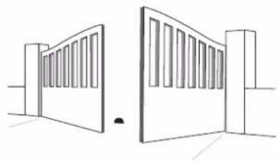
Risk of trapping and crushing

natural_image
Silhouette of a person standing inside a door with a vertical pipe inserted (no text or symbols)

Obstacle detection built into the motor.
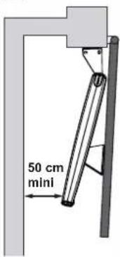
If there is an area between the gate leaves and the surrounding fixed elements where someone could get trapped, you must leave a minimum distance of 50 cm between the gate leaves and the fixed sections.
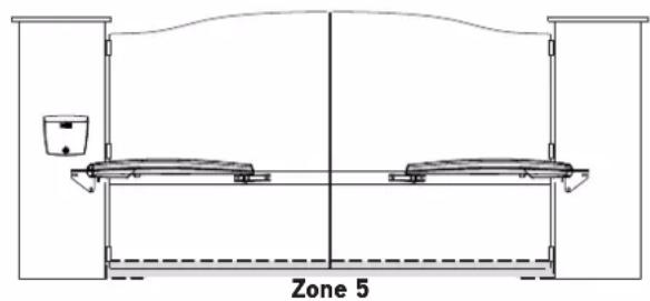
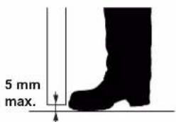
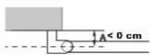
ZONE 5
Risk of feet being trapped

Solution:
If there is an area where feet could be trapped between the bottom of the gate leaves and the ground, you must leave a distance between the bottom of the gate leaves and the ground of a minimum of 12 cm or a maximum of 5 mm.

▶ Contents of the pack
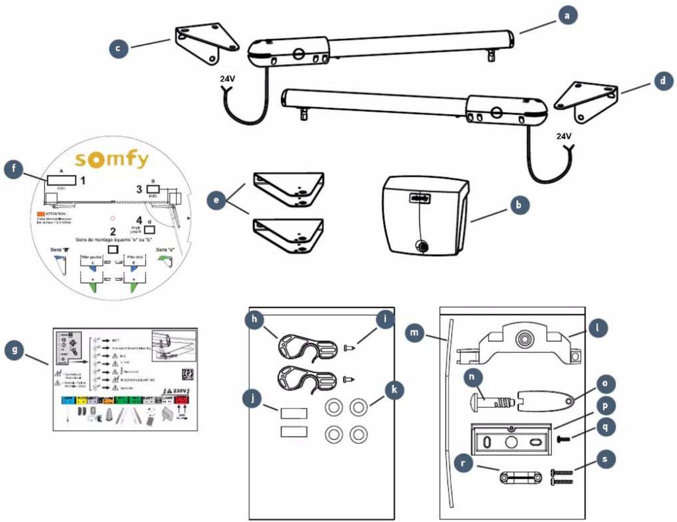
No. Designation Quantity No. Designation Quantity
| a | 24V cylinder x2 Control unit accessories pouch | |
| b | Control unit | x1 |
| c | Wall/pillar left-hand mounting bracket | x1 |
| d | Wall/pillar right-hand mounting bracket | x1 |
| e | Gate leaf mounting bracket | x2 |
| f | Disc for reading dimensions | x1 |
| g | Summary label | x1 |
| Cylinder accessories pouch | ||
| h | Unlocking mechanism | x2 |
| i | Unlocking mechanism screw | x2 |
| j | Pin for securing the cylinder to the wall/pillar bracket | x2 |
| k M8x22 flat washer x4 | ||
| l | Battery bracket | x1 |
| m | Sealing strip | x1 |
| n | Unit cover screw | x1 |
| o | Unit cover unlocking key | x1 |
| p | Wall mounting bracket | x1 |
| q | Screw for securing the unit to the bracket | x1 |
| r | Cable clamp x1 | |
| s | Cable clamp bolt | x2 |
▶ Product description
▶ Space requirements
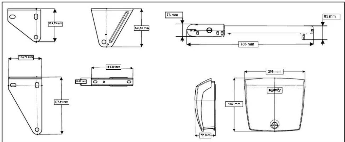
▶ Field of application
This automatic control system has been designed to motorise residential double door gates for a detached house.
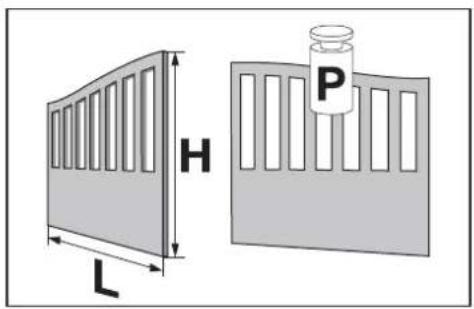
Dimensions and weight of the gate leaves
| Max. weight per leaf (P) 200 kg | |
| Max height per gate leaf (H) 2 m | |
| Min./Max. width per leaf (L) 1.25/2 m |
The type of gate (solid/open-worked) and the weather conditions (presence of strong winds), may reduce these maximum values (see table below).
Dimensions and weight of gate leaves which can be motorised, based on the wind strength
| Wind strength Effect Product SGS LINE |  | ||
| ≥ 80 Km/h The wind is too strong to walk against Min./Max. width. | Max weight. | 1.25/1.5 m200 kg | |
| < 80 Km/h>40 Km/h | The branches of the trees are moving | Min./Max. width.Max weight. | |
| Min./Max. width.Max weight. | |||
| ≤ 40 Km/h Sand is flying | Min./Max. width.Max weight. | ||

Openworked gate
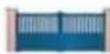
Semi-openworked gate Solid gate

▶ General view of the installation
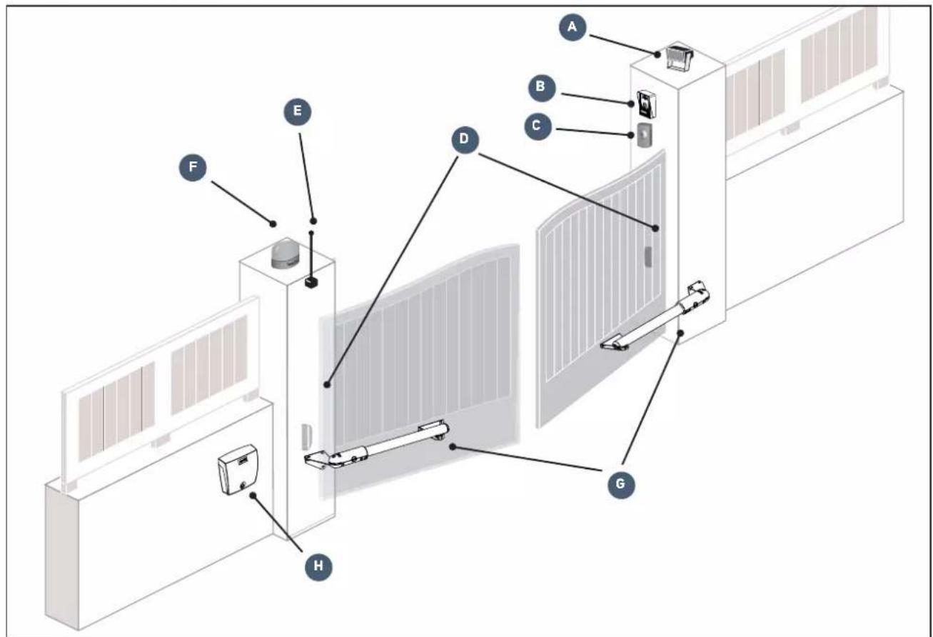
| Mark | Descr |
| A | Area lighting* E Offset antenna* |
| B Video entry phone* F Flashing light | |
| C Key lock* G Motors | |
| D Photoelectric cells H Control unit | |
| Mark | |
*optional accessories
▶ Presentation of the control electronics

| No. Description Function | |||
| A | Button ➕ | Reactivation of the control electronics | |
| B | RADIO indicator light | Lights up each time the control electronics receive a radio command | |
| C | Indicator light ➕ | Lights up during activation/deactivation of the pedestrian opening | |
| D | Indicator light ➕ | On automatic closure of the gate is activated | |
| Off | automatic closure of the gate is not activated | ||
| Flashing | the "automatic closing" parameter is selected | ||
| E | Indicator light P1 | Not used | |
| F | RESET indicator light | On | the settings alone or the settings and the radio control points are deleted |
| Flashing | the settings and radio control points deletion function is selected | ||
| G | Indicator light ➕ | On | the motorisation functions correctly - the control electronics are reactivated |
| Off | the motorisation functions correctly - the control electronics are in standby | ||
| Flashing see "Diagnostics" page 31 | |||
>Prerequisites for installation
▶ Pre-installation checks
Gate
Your gate is in good condition: it opens and closes normally with ease.
It remains horizontal throughout its travel. It opens inwards towards your property.

natural_image
Two simple line drawings of a two-story door with slatted top and front panel, no text or symbols present.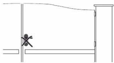
natural_image
Simple line drawing of a doorway with a cross symbol at the center (no text or labels)Reinforcements
The motors must be secured to the horizontal reinforcements of the gate leaves, which should ideally be positioned 1/3 up the gate.
If there are no reinforcements, use metal reinforcement plates approximately 4 mm thick.
Closing end stops on the ground
The gate's closing travel must be defined by end stops firmly fixed in the ground. The opening stops are integrated in the motor (see "Adjusting the opening stop" page 19).
Mechanical lock
If the gate is equipped with a mechanical lock, it must be removed.
Pillars
The pillars must have a robust structure and be at least 21 cm wide. If they do not, improvements may have to be made to your pillar to guarantee correct installation and to ensure that the bracket stays in place.
It is not recommended to mount the bracket level with the pillar: risk of spalling.
Electrical pre-equipment
Cables required
- Power supply: 3 × 1.5 ~mm^2 cable or 3 × 2.5 ~mm^2 for outdoor use (type H07RN-F as minimum requirement).
- Connection between the motors: 2 x 1 mm ^2 cable; fit an IP 55 junction box to protect the connection between the cable leaving the motor and the extension which goes to the control unit.
- Linking of cells: 2 × 0.75 ~mm^2 cable;

Provision must be made for the power supply cable to be fed through in accordance with the electrical standards in force in the country of use.


Cable feed
- Underground cables must be equipped with a protective sheath with a sufficient diameter to contain all the cables.
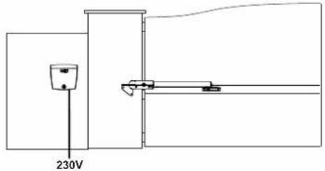
- Fit a 230 V electrical input as close as possible to the control unit.
▶ Cables required

If a cable conduit cannot be made, use a cable grommet which will withstand the weight of vehicles (ref. 2400484).

Details of the wiring are given in the section entitled "Wiring the accessories" page 22.

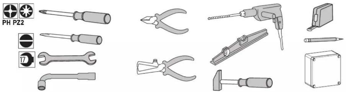
▶ Tools required for installation (not provided)
natural_image
Collection of various electrical tools and components including screwdrivers, pliers, and a power tool (no text or labels visible)▶ Hardware required for installation (not provided)
This information is provided for information purposes.
| For securing the... Quantity | |||
| BRACKETS TO THE PILLARS/WALLS | |||
 | Hardware adapted to the material of the pillar/wall (screws, studs, chemical seals, etc.):- diameter: 8 to 10 mm- hex head | 6 | |
| Washers:- internal diameter: 8 to 10 mm- external diameter: 16 to 20 mmNuts:- diameter: 17 mm | 6 | ||
| BRACKETS TO THE GATE LEAVES | |||
 | Hardware adapted to the material of the gate leaf reinforcement:- diameter: 8 mm- length adapted to the thickness of the gate leaf reinforcement | 6 | |
| Washers supplied- internal diameter: 8 mm- external diameter: 22 mm | 6 | ||
| CONTROL UNIT | |||
 | Hardware adapted to the material of the pillar/wall- screw diameter: 3.5 to 4.5 mm - raised or flat-head screws- Type "S" rawl plug for concrete: S5, S6 or S8 | 4 | |
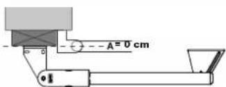
1.1 Measuring the dimensions
Take the dimensions using disc (f) to determine the position of the motors on the pillars.
Note: For these measurements, the gate leaves and their hinge pins are assumed to be on the same axis.
N.B.: You must leave a minimum distance of 50 cm between the gate leaves and the fixed sections (see "Risk prevention" page 4).

flowchart
graph TD
    A["1 Measure dimension A."] --> B["Transfer the measured dimension A on the disc."]
    B --> C["2 The direction of fitting (e or E) of the cylinder mounting bracket is stated."]
    C --> D["3 Determine dimension B"]
    D --> E["4 The maximum opening angle α is indicated."]
    E --> F["5 Observe the maximum opening angle given by the disc."]

    subgraph Section 1
        G["1 mm"] --> H["N.B Dimensions not recommended for gate leaves > 2 metres"]
    end

    subgraph Section 2
        I["2 Sens "E" with Piler gauche, E, E"] --> J["Sens "e" with Piler droit"]
    end

    subgraph Section 3
        K["3 B mm"] --> L["somfy"]
        L --> M["Attention: Cate disconsultées pour les vêtrus = 0.2 metres"]
        M --> N["Angle jump/α"]
        N --> O["Sens de montage équerre "e" ou "E""]
    end

    subgraph Section 4
        P["4 Angle up to α"] --> Q["Observe the maximum opening angle given by the disc."]
    end

    style Section 1 fill:#f9f,stroke:#333
    style Section 2 fill:#ccf,stroke:#333
    style Section 3 fill:#cfc,stroke:#333
    style Section 4 fill:#fcc,stroke:#333

Recommended: dimension A is negative
If dimension A is negative, the gate leaf hinge is located in front of the pillar. We recommend that you add a shim so that the cylinder mounting bracket is aligned with the gate leaf hinge and A is 0 cm.
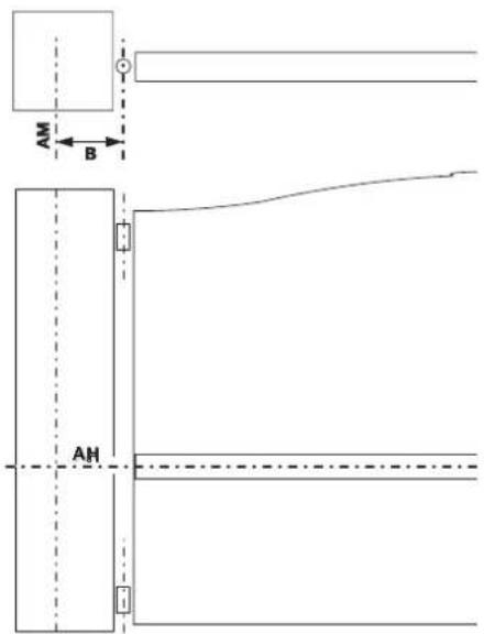
1.2 Mounting the pillar brackets
▶ Marking the AM and AH axes
- Transfer dimension B onto the pillar using the hinge axis and mark a vertical axis AM on the pillar.
- Mark the horizontal axis AH on the pillar, halfway up the reinforcement.

Check before proceeding to the next step Have you marked the AM and AH axes?
Drilling the pillars
1
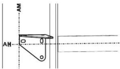
Align the markings made on the bracket with the AH axis and align the edge of the bracket with the AM axis.
Note: The markers marked on the bracket are underneath the oblong holes.

Position the bracket in direction e or E defined in step 2 of measuring the dimensions (see page 12).
Left-hand pillar Right-hand pillar
Direction E Direction E Direction E


Take care to ensure the bracket is fitted the right way up.
Correct orientation

Incorrect orientation
2

natural_image
Technical line drawing of a mechanical clamp or bracket assembly (no text or symbols)Check that the bracket is horizontal, then mark the mounting holes for the bracket.
3

natural_image
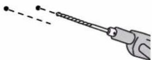
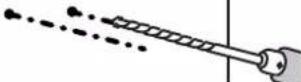
Diagram showing a tool interacting with a wire and a separate panel, no text or symbols presentDrill 3 holes in each pillar in the locations marked (see page 11 for the drilling diameter corresponding to suitable hardware).
▶ Securing the pillar mounting bracket
1

natural_image
Pure mechanical linkage diagram without any text, numbers, or symbolsSecure the mounting bracket to the pillar with hardware adapted to the mounting support.
2

natural_image
Technical line drawing of a mechanical bracket or clamp assembly (no text or symbols)Check that the bracket is at the right level. Retighten if necessary.

Check before proceeding to the next step
Have you checked that the brackets are perfectly horizontal on the cylinders?
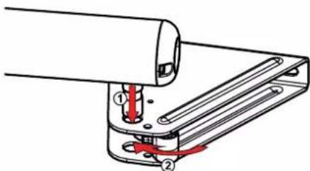
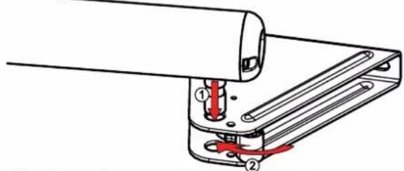
▶ Fit the cylinder onto the mounting bracket
1
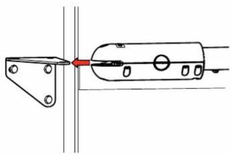
natural_image
Technical line drawing of a mechanical assembly with a red arrow indicating direction (no text or symbols)Fit the cylinder onto the mounting bracket. Block it with the pin (j).
2

natural_image
Technical line drawing of a mechanical clamp or bracket assembly (no text or symbols)1.3 Securing the motors to the gate leaves

Never operate the cylinder before having finished mounting it on the gate leaf. If this happens, the internal cylinder could be incorrect and malfunctions could occur.
1


Fix the unlocking mechanism (h) onto the gate leaf mounting bracket (e) using screw (i).
2

Fit the cylinder onto the leaf mounting bracket.
Clip the unlocking mechanism onto the cylinder catch to secure it.
3

natural_image
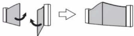
Diagram of a balanced lever system with two supports and directional arrows indicating motion (no text or labels)Close the gate.

In the closed position, the gate leaves must be firmly against the ground stop and the cylinder against its internal stop.
4

natural_image
Technical line drawing of a mechanical assembly with no visible text or symbolsPush the gate leaf mounting bracket against the gate leaf reinforcement. Check that the cylinder is level.
5
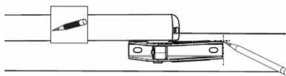
natural_image
Technical line drawing of a mechanical assembly with a tool inserted into a cylindrical component (no text or symbols)Make the markings on the sides of the gate leaf mounting bracket.
6

Unclip the unlocking mechanism, then remove the cylinder from the gate leaf mounting bracket.
7

natural_image
Technical line drawing of a mechanical component with a rod inserted, showing alignment lines (no text or symbols)Reposition the gate leaf mounting bracket then mark the mounting holes in the centre of the oblong holes.
8

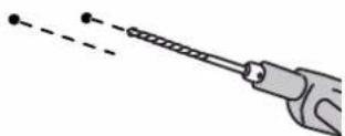
natural_image
Illustration of a handheld tool with a string and two dots, no text or symbols presentDrill the gate leaves with a diameter of 8.
9
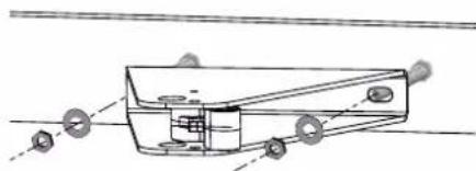
natural_image
Technical line drawing of a mechanical component with mounting holes and internal structure (no text or symbols)Secure the gate leaf mounting bracket to the two points on the gate leaves using screws suited to the reinforcement material and the washers (j) supplied.

The washers (k) provided must be fitted.
10
Fit the cylinder. Clip the unlocking mechanism on the catch to secure it.

Check before proceeding to the next step Have you checked that the cylinders are perfectly horizontal?
1.4 Installing the control unit
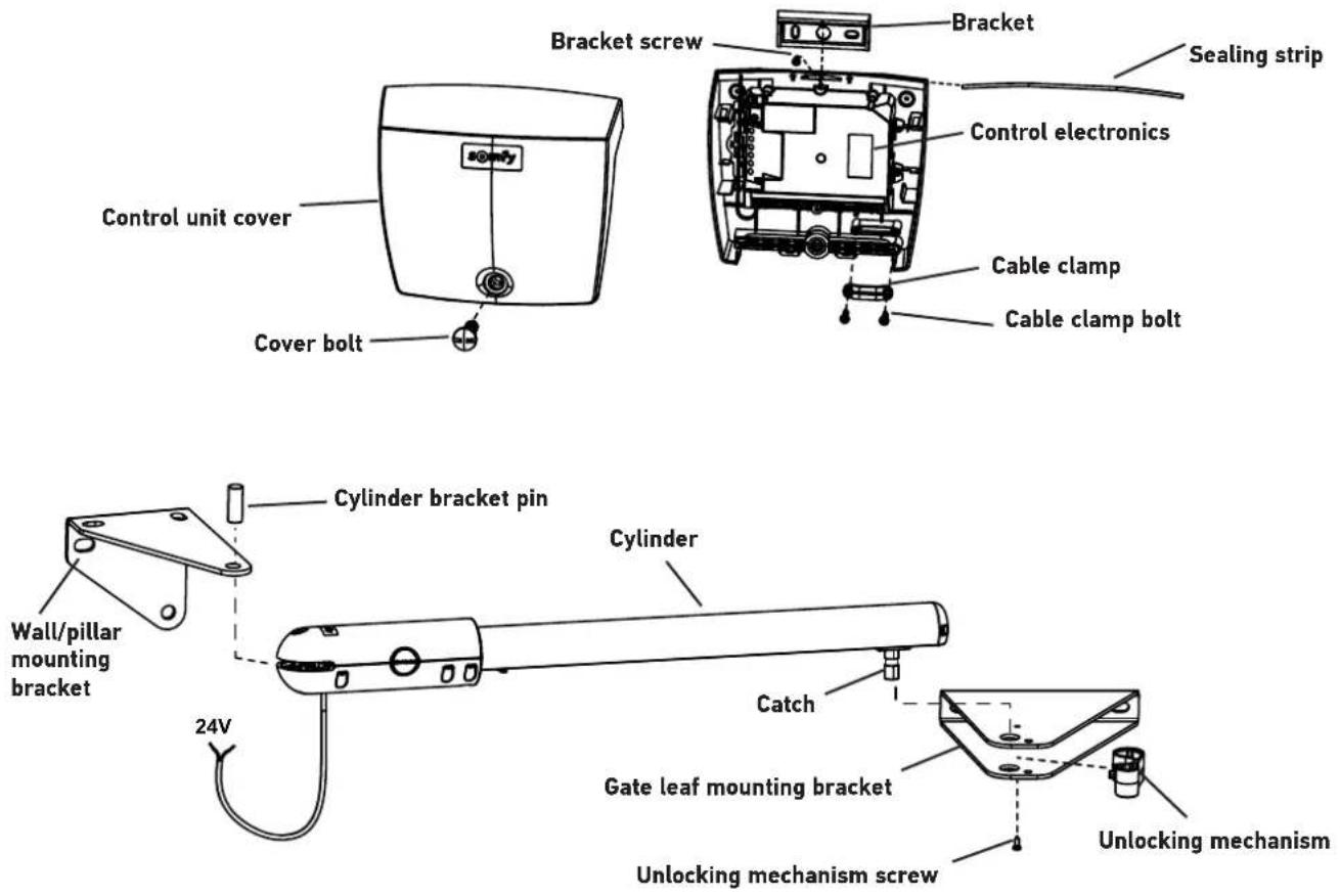
▶ Position of the control unit
The unit will be mounted on a pillar/wall on the side where the power supply arrives.
- Installing the sealing strip
Fit sealing strip (m) inside the top of the control unit.
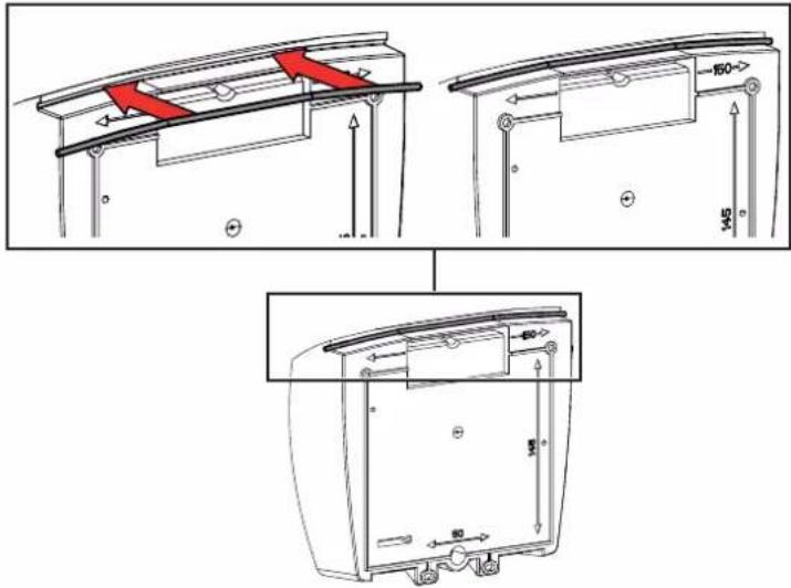
▶ Checking the position of the antenna
For optimum performance, it is essential that the antenna is correctly positioned.

Do not cut the cut the antenna wire.

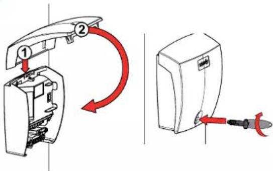
▶ Securing the control unit
1

natural_image
Technical line drawing of a mechanical component with no visible text or symbols- Position the unit mounting bracket (p) against the pillar/wall.
- Check that it is horizontal by placing a spirit level in the intended location.
- Mark the mounting points for the bracket.
2

natural_image
Illustration of a hand holding a pen with a dashed line indicating motion or alignment (no text or symbols)Remove the bracket and drill the pillar/wall. The drilling diameter is to be defined based on the type of screws used for mounting (see page 11).
| 3 |  | Secure the bracket to the pillar/wall. | |
| 4 |  | Position the base of the unit to mark the 2 mounting points at the bottom of the unit. | |
| 5 | 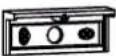 | Remove the base of the unit then drill the pillar/wall. The drilling diameter is to be defined based on the type of screws used for mounting (see page 11). | |
 | |||
| 6 | 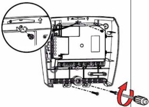 | Secure the base of the unit to the pillar/wall: 1 screw (q) to secure the unit to the bracket + 2 screws to secure the unit to the pillar/wall. | |
1.5 Connecting the motors

Motor M1 activates the gate leaf which:
- opens first and closes last,
- opens for pedestrian access.


flowchart
graph TD
    A[" "] --> B["M1 on the left"]
    B --> C[" "]
    C --> D[" "]
    D --> E["M1 on the right"]
    E --> F[" "]
    style A fill:#f9f,stroke:#333
    style E fill:#f9f,stroke:#333
With the gate closed, identify the gate leaf that opens first.
Motor M1 activates this gate leaf.

Connect the motors as indicated in the table below:
Connect motor wire... to terminal ...
| M1 | blue 10 | |
| brown 11 | ||
| M2 | blue 12 | |
| brown 13 |

1.6 Connecting to the power supply

For your safety, these operations must be carried out with the power supply switched off.
Use a 3 1.5 x 1.5 mm ^2 cable for outdoor use (at least H07RN-F type).
The cable clamp supplied must be used. For all low-voltage cables, ensure that they can withstand traction of 100 N.
Check that the conductors have not moved when this traction has been applied.


On a 3 x 1.5 mm ^2 type cable, prepare 2 x 4 cm wires (live and neutral).


- Connect live and neutral to terminals 16 and 17 (red "230 V" label).
- Immobilise the 230 V power cable with the cable-clamp provided (r).
- Fit a terminal block on the earth wire (yellow/green) and store it in the control unit.
2.1 Switching the installation on
The Indicator light flashes (twice).
The motorisation is switched on and awaiting auto-programming.
If the ⏻ indicator light does not come on or the number of flashes is not as expected: see "Diagnostics" page 31.
2.2 Adjusting the opening stop

Opening end stop
The opening stops are integrated into the cylinder. They delimit the travel of the gate leaf when opening.
N.B.: Your installation must be equipped with closing stops secured to the ground to mark out the travel of the gate when closing.
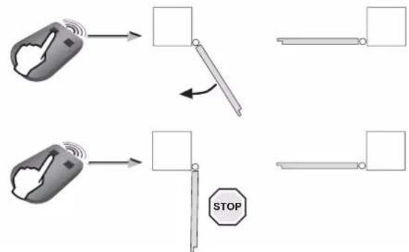
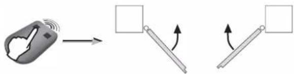
During this phase, pressing button 1 on the programmed remote control only causes the gate to open and stop (1st press = open, 2nd press = stop, 3rd press = open, 4th press = stop, etc.), you can therefore set the desired opening position in several increments. it will be possible to close the gate once the opening stops are installed.
1
flowchart
graph TD
    A["Hand gesture with wireless signal"] --> B["Stop"]
    C["Hand gesture with wireless signal"] --> D["Stop"]
    B --> E["Arrow to right"]
    D --> F["Arrow to left"]
    E --> G["Horizontal bar with arrow"]
    F --> H["Horizontal bar with arrow"]
    G --> I["Horizontal bar with arrow"]
    H --> J["Horizontal bar with arrow"]
    I --> K["STOP"]
- Press button 1 on the remote control.
After a few seconds, the first gate leaf opens, slowly. If the gate leaf does not open, check that the motors are wired as shown on page 18.
- Press button 1 on the remote control again to stop the gate leaf in the desired opening position.
2

natural_image
Technical diagram showing mechanical assembly with a bracket and rail, plus a close-up of a mechanical component with a red arrow indicating rotation (no text or symbols)Position the opening stop in contact with the cylinder knob then tighten the stops using an Allen key, diameter 3 (2 screws per stop).

Perform 2 full turns of the key after contact.
3
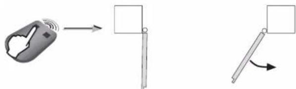
Press button 1 on the remote control. The second gate leaf opens.
4

Press button 1 on the remote control again to stop the gate leaf in the desired opening position.
5

natural_image
Technical diagram showing mechanical assembly with a rotating component and a red-handled tool (no text or symbols)Position the opening stop in contact with the cylinder knob then tighten the stops using an Allen key, diameter 3 (2 screws per stop).

Perform 2 full turns of the key after contact.
6
Press button 1 on the remote control to close the gate completely. The leaves close one after the other.

Check before proceeding to the next step Have you set the position of the opening stop on each motor?
2.3 Gate travel auto-programming
Check that the installation is switched on: the ◎indicator light flashes (twice).
Case 1: First commissioning of your motorisation
Press button 1 on the remote control to initiate a COMPLETE opening motion of the gate.
When the gate is completely open, press button 1 on the remote control again to initiate a COMPLETE closing movement of the gate.
When the gate is completely closed, the ⏻ indicator light on the control unit should be CONTINUOUSLY LIT.
Case 2: You have just deleted the settings
Launch 4 full gate opening and closing movements. Upon completion of the 4 movements, indicator light ⏻ on the control unit must be CONTINUOUSLY LIT.


The gate movements must not be interrupted (complete opening/closing). If they are interrupted, programming will resume the next time the opening command is issued.
If indicator light ⏻ flashes, relaunch auto-programming of the leaf travel (4 full opening and closing movements). If the indicator light ⏻ continues to flash, refer to "Diagnostics" page 31.
If the gate re-opens at the end of the closing movement, loosen and offset the gate leaf brackets slightly towards the centre of the gate.

WARNING
Once installation is complete, it is essential to check that the obstacle detection complies with annex A of the standard EN 12 453.
2.4 Closing the control unit
1

Affix summary label (g) to the back of the control unit cover. Close the control unit and screw in the cover.
2
2.5 Standby/Reactivating the control electronics
i
Once the auto-programming process has been completed, the electronics automatically switch to standby after 5 minutes of inactivity to save energy. In standby mode, all indicator lights are off.
To check whether the motorisation is switched on or to check/modify the parameter setting, press the 🎨 button for 2 seconds to reactivate the electronics. The electronics will automatically switch to standby after 5 minutes of inactivity.
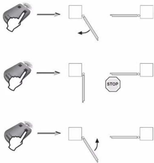
2.6 Completely opening and closing the gate
i
The remote controls supplied with the kit are already memorised and programmed so that button 1 on the remote controls activates complete opening of the gate.
Button 1


flowchart
graph TD
    A["Hand gesture"] --> B["Arrow to right"]
    B --> C["Arrow left"]
    C --> D["Arrow right"]
    D --> E["Arrow down"]
    E --> F["Arrow down"]
    F --> G["Arrow down"]
    G --> H["Arrow down"]
    H --> I["Arrow down"]
    I --> J["Arrow down"]
    J --> K["Arrow down"]
    K --> L["Arrow down"]
    L --> M["Arrow down"]
    M --> N["Arrow down"]
    N --> O["Arrow down"]
    O --> P["Arrow down"]
    P --> Q["Arrow down"]
    Q --> R["Arrow down"]
    R --> S["Arrow down"]
    S --> T["Arrow down"]
    T --> U["Arrow down"]
    U --> V["Arrow down"]
    V --> W["Arrow down"]
    W --> X["Arrow down"]
    X --> Y["Arrow down"]
    Y --> Z["Arrow down"]
- Gate closed: press button 1 on the remote control to open the gate fully.
- Gate moving: Press button 1 on the remote control to stop the gate.
- Gate open: Press button 1 on the remote control to close the gate.
2.7 Obstacle detection
If an obstacle is detected (abnormal force on the motorisation):
- When the gate is opening: the gate will stop.
- When the gate is closing: the gate will stop and reopen.
2.8 User training
All users must be trained on how to safely use this motorised gate (standard use and unlocking principle) and on the mandatory periodic checks.

For your safety, these operations must be carried out with the power supply switched off.

You are advised to perform auto-programming of the gate travel before connecting the accessories (photoelectric cells, flashing light, etc.)
3.1 Photoelectric cells

It is not possible to connect a second set of photoelectric cells on this motorisation.
▶ Installation
After wiring the photoelectric cells:
- switch the motor on again,
- start a gate opening or closing procedure.
The photoelectric cells are recognised by the control electronics once this movement is complete.
▶ Operation with photoelectric cells
If the cells are blocked when closing the gate, the gate will stop and reopen.

or

▶ In the event of photoelectric cell disconnection
After disconnecting the photoelectric cells, switch the motor on again and perform the "Deactivating automatic closing" procedure, page 26.
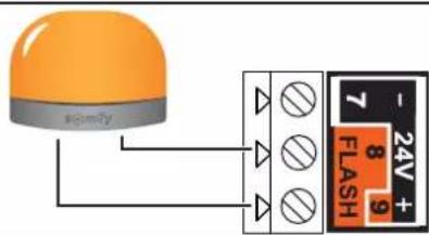
3.2 Flashing light

10 W - 24 V bulb MAXIMUM - use of a bulb with power greater than 10 W - 24 V can cause motorisation malfunctions.
▶ Operation of the flashing light
The light flashes while the gate is moving.
3.3 Battery (optional)

This accessory is not compatible with solar power.

To increase the operation time of the battery during use, the wired controls are deactivated and the gate can only be controlled using the remote controls and the radio control points.
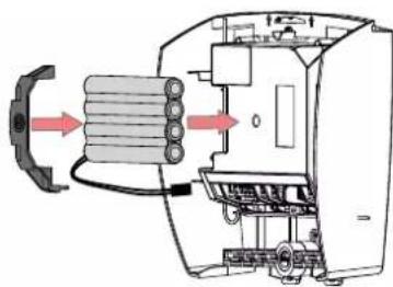
natural_image
Diagram of a mechanical device with internal components and directional arrows indicating flow or movement (no text or symbols present)
natural_image
Technical line drawing of a mechanical device with internal components (no text or symbols)The backup battery ensures the operation of the gate in the event of an electrical power failure.
The ⏻ indicator light flashes (1 pulse) when the motor is battery-operated.
▶ Battery technical data
- Battery life: 10 continuous cycles or 24 hours on a gate in perfect condition.
- Optimum charge time before using the battery: 48 hours.
• Service life: 3 years.
To ensure an optimum battery life, switch the gate's electric power supply off at least 3 times a year to run a number of cycles using the battery.
3.4 Offset antenna (optional)

The antenna wire can be replaced with an offset antenna with a greater range. This is placed on top of the pillar and must be clearly accessible.
It is connected to terminals 1 and 2 (blue "ANT" label) on the control unit:
• the wire core on terminal 1,
• the ground strap on terminal 2.

3.5 Video entry phone (optional)

This accessory is not compatible with solar power. Only connect one non-powered dry contact.

3.6 Key lock (optional)

This accessory is not compatible with solar power.

3.7 Area lighting (optional)

This accessory is not compatible with solar power. Only use halogen or incandescent bulbs for area lighting, 500 W maximum.
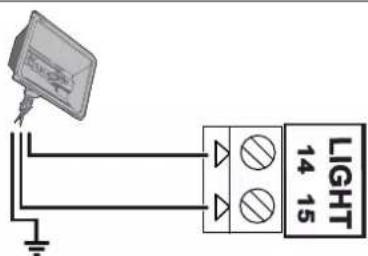
▶ Area lighting operation
Area lighting comes on each time the motor is started up. It goes out automatically 1 minute and 30 seconds after movement has finished.
3.8 Solar power (optional)

Never connect your motor to a 230 V power supply when it is connected to a solar power supply, as this may damage the motor's electronics unit.

When the motor is running on the solar feed:
- only the remote controls and radio control points can be used to control the gate (wired controls are deactivated),
- the wired safety accessories (photoelectric cells, flashing light) remain active.
4.1 Pedestrian opening
▶ Pedestrian opening operation
Pedestrian opening(motor M1) by pressing the activated button.
Stop when moving by pressing the activated button again.
Close by pressing the activated button again.
▶ Activating the pedestrian opening
i
Button 1 on 2- or 4-button remote controls cannot be programmed to control pedestrian opening. See "Description of the remote controls" page 27 for more information.
12

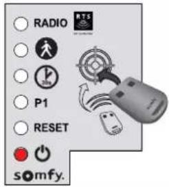
Press the button on the control electronics for 2 seconds. The indicator light comes on.
●

Position the remote control on the control electronics target.
●
Press button 2 on the remote control. The "RADIO" and 📁 indicator lights come on then go out. Pedestrian opening is activated on this button.
i
Move away from the control electronics when testing pedestrian opening.
▶ Deactivating pedestrian opening
Repeat the "Activate pedestrian opening" procedure using the button for which the pedestrian opening must be deactivated. The indicator light comes on then goes out. The pedestrian opening is deactivated on this button.
4.2 Automatic closing
▶ Automatic closing operation
Press button 1 on the remote control to open the gate.
The gate closes again after 30 seconds or 5 seconds if the photoelectric cells detect a passage.
The automatic closing can be interrupted by pressing button 1 on the remote control. To then close the gate, press button 1 on the remote control again.
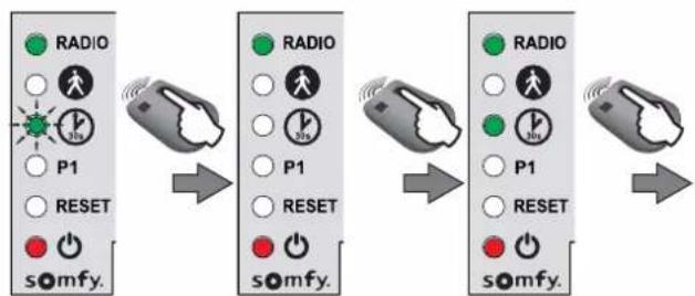
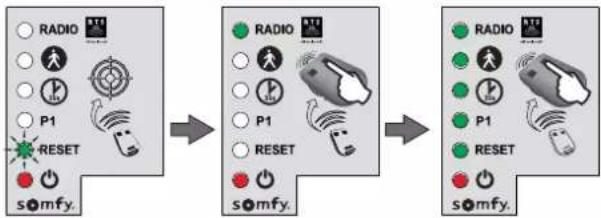
▶ Activating automatic closing

Automatic closing can only be activated if the photoelectric cells are connected and recognised by the motor's control electronics.

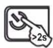
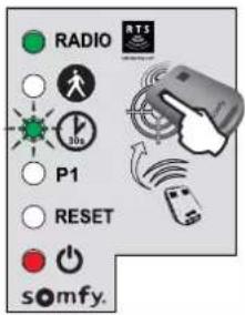
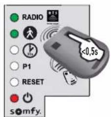
Press the button on the control electronics for 2 seconds. The indicator light comes on.


Position the remote control on the control electronics target.


Keep button 1 of the remote control depressed until the indicator light flashes.

Once step 3 has been carried out, you can carry out the following steps remotely (without placing the remote control on the target).

flowchart
graph LR
    A["Radio"] --> B["P1"]
    B --> C["RESET"]
    C --> D["somfy."]

    E["Radio"] --> F["P1"]
    F --> G["RESET"]
    G --> H["somfy."]

    I["Radio"] --> J["P1"]
    J --> K["RESET"]
    K --> L["somfy."]
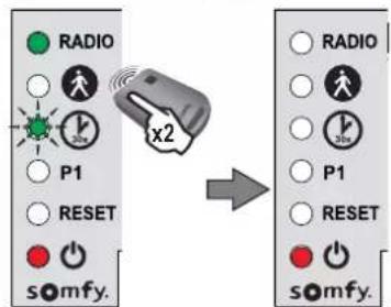
Keep button 2 on the remote control depressed until the indicator light goes out and is then lit constantly.


When you release button 2, the ⏻ indicator light flashes; press button 1 on the remote control twice. The ⏻ indicator light remains lit.
Automatic closing is activated.
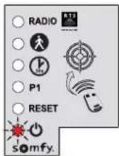
▶ Deactivating automatic closing
12

Press the button on the control electronics for 2 seconds. The indicator light ⏻ comes on.
Position the remote control on the control electronics target.
Keep button 1 of the remote control depressed until the ⏱ indicator light flashes.
45

Press button 2 on the remote control. The indicator light flashes.

●
Press button 1 on the remote control twice.
The image is too blurry to recognize any text content.
The indicator light ⏻ is off. Automatic closing is deactivated.
5.1 Description of the remote controls
Depending on the choice of parameter settings, Somfy RTS remote controls can control:
• complete opening of the gate
• pedestrian opening of the gate
- another Somfy RTS device (example: garage door motor, roller shutter, etc.)

2-button remote control

4-button remote control
i
The remote controls supplied with the kit are already memorised and programmed so that button 1 on the remote controls activates complete opening of the gate.
i
You can memorise up to 16 control points (remote control, other radio control point). If you memorise a 17th control point, the first point memorised will automatically be deleted.
i
If you wish to program pedestrian opening, it must be programmed on the button following programming of the complete opening (e.g. complete opening controlled by button 2, pedestrian opening controlled by button 3). It is not possible to programme pedestrian opening on button 1 of the remote controls.
▶ Possibilities for programming the 2-button remote control
| Button 1 | Button 2 | |
| Possibility 1 | Complete opening Pedestrian opening or other Somfy RTS automatism | |
| Possibility 2 Another | Somfy RTS device Complete opening | |
▶ Possibilities for programming the 4-button remote control
| Button 1 | Button 2 | Button 3 | Button 4 | |
| Possibility 1 | Complete opening Pedestrian opening or other Somfy RTS automatism | Another Somfy RTS automatism | Another Somfy RTS automatism | |
| Possibility 2 Another Somfy RTS automatism | Complete opening Pedestrian opening or other Somfy RTS automatism | Another Somfy RTS automatism | ||
| Possibility 3 Another Somfy RTS automatism | Another Somfy RTS automatism | Complete opening Pedestrian opening or other Somfy RTS automatism | ||
| Possibility 4 Another Somfy RTS automatism | Another Somfy RTS automatism | Another Somfy RTS automatism | Complete opening | |
▶ Using a 3-button remote control
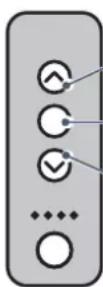
Opening To open the gate completely, press the "Up" button on the remote control.
Stop To stop the gate while it is moving, press the central button on the remote control.
Closing To close the gate, press the "Down" button on the remote control.
i
The 3-button remote control cannot be used to change the motor settings.
5.2 Adding a remote control
▶ 2- or 4-button remote control
12

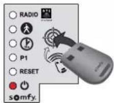
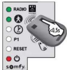
Press the 🎨 button on the control electronics for 2 seconds. The indicator light ⏻ comes on.
The image is too blurry to recognize any text content.

Position the new remote control to be programmed on the control electronics target.
C

Briefly press the button on the remote control to be programmed. The RADIO indicator light will come on then go out when you release the button on the remote control.
Complete opening is programmed on this button.
▶ 3-button remote control
1

Press the 🎨 button on the control electronics for 2 seconds. The indicator light ⏻ comes on.
●

Position the new remote control to be programmed on the control electronics target.
●
Briefly press a button on the remote control to be programmed. The RADIO indicator light will come on then go out when you release the button on the remote control. The remote control has been memorised.
5.3 Deleting a remote control
see "Clearing the settings" page 30.

The motorisation must be disconnected from any power supply during cleaning and maintenance and when parts are replaced.
6.1 Assistance
If the fault remains or for any other problem or enquiry relating to your motorisation, visit www.somfy.com
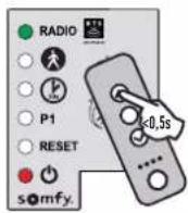
6.2 Replacing the remote control battery
The service life of the battery is generally 2 years.
12
natural_image
Mechanical device with a tool and magnified inset showing a close-up of a tool (no text or symbols visible)Remove the clip from the remote control.
●

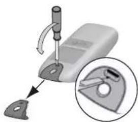
natural_image
3D diagram of a device showing internal components with arrows indicating movement (no text or symbols)Insert the screwdriver in the slot and lift the cover.
C
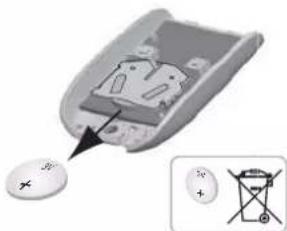
natural_image
Close-up of a small electronic device with a circular button and an inset showing a battery symbol (no text or labels visible)Remove the battery using a screwdriver.
●
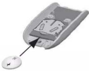
natural_image
Close-up of a computer mouse with a cursor pointing to the interior (no text or symbols visible)Replace the battery (3 V CR 2430 or CR 2032).
6.3 Clearing the settings
When should I clear the settings?
• After programming the gate leaf travel, if you change the opening position stop or if you modify the motor wiring.
- If the gate opens at random due to normal wear of the gate.
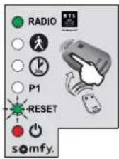
1

Press the button on the control electronics for 2 seconds. The indicator light comes on.


Place the memorised remote control on the target.


Keep button 1 of the remote control depressed until the indicator light flashes.


Press button 1 on the remote control once. The "RESET" indicator light flashes.
5
To clear the settings\*

flowchart
graph LR
    A["Radio"] --> B["Reset"]
    B --> C["somfy."]
    D["RADIO"] --> E["Reset"]
    E --> F["somfy."]
    G["P1"] --> H["Reset"]
    H --> I["somfy."]
    J["OK"] --> K["Reset"]
    K --> L["somfy."]
Keep button 2 of the remote control depressed until the "RESET" indicator light comes on.
5
To clear the settings\* and the memorised remote controls/control points
flowchart
graph LR
    A["Radio"] --> B["P1"]
    B --> C["RESET"]
    C --> D["somfy."]
    D --> E["RADIO"]
    E --> F["P1"]
    F --> G["RESET"]
    G --> H["somfy."]
    H --> I["RADIO"]
    I --> J["P1"]
    J --> K["RESET"]
    K --> L["somfy."]
Keep button 2 of the remote control depressed until all the indicator lights come on.

The indicator light flashes twice (see "Gate travel auto-programming" page 20).
*Gate travel, deactivation of the settings, etc.
6.4 Unlocking/locking the motors
When unlocking the motors, the gate may be manoeuvred manually if there is an electrical fault.
1

Unlocking the motors
Unclip the unlocking mechanism, then remove the cylinder from the gate leaf mounting bracket.
2
Locking the motors
Fit the cylinder. Clip the unlocking mechanism on the catch to secure it.
6.5 Diagnostics
| DIAGNOSTICS REPAIRS | ||
| The motors are not responding to remote control commands | The remote control range is reduced - | Check the remote control battery (see “Replacing the remote control battery”, page 29).- Check the control unit antenna (wiring, position, see page 16).- Check that there are no outside elements that may be interfering with the radio signal (electric pylon, metal reinforced walls, etc.). If this is the case, fit an offset antenna. |
| Non-memorised remote control Memorise the remote control (see page 28). | ||
| Poorly wired motors Check the motor wiring (see page 18). | ||
| The control unit's indicator light is off | The electronics unit is on standby | Press button for 2 seconds to reactivate the electronics. |
| No power supply to the control electronics | - Check the power supply.- Check the power supply cable. | |
| The control unit's indicator light flashes: | ||
| 1 flash Operation using the backup battery Check the mains power supply. | ||
| 2 flashes | Motor waiting for auto-programming | Start the gate travel auto-programming procedure (see page 20). |
| 3 flashes Faulty photoelectric cells | - Check that there is nothing obstructing the cells.- Check the cell alignment.- Check the cell wiring (see page 22).- If the cells are deliberately disconnected, perform the “Deactivating automatic closing” procedure, page 26. | |
| 4 flashes Permanent control on "START" of the electronic unit (terminals 5-6) | Check the accessories connected to the electronic unit's "START" output. | |
| 5 flashes Electronics thermal safety activated | Allow the electronics to cool down until the indicator light comes on continuously. | |
| 6 flashes Short circuit of electronics unit's "BUS" output (terminals 3-4) | Check the accessories connected to the electronic unit's "BUS" output. | |
| Short circuit of electronics unit's "24 V output" (terminals 7-9) | ||
| Short circuit of the electronics unit's "flashing light" (terminals 8-9) | ||
| Motor short circuit Check the motor wiring (see page 18). | ||
| 7 flashes Electrical fault Contact Somfy assistance. | ||
| The gate reopens at the end of the closing motion | Unscrew the gate leaf brackets and offset them slightly towards the centre of the gate. | |
| Power supply 230 V-50Hz/24 V (with solar power) | |
| Motor type 24 V | |
| Motor output 120 W | |
| Max. power consumed(with area lighting) | 600 W |
| Standby consumption 3 W (without accessories) | |
| Maximum frequency of movements per day 20 cycles per day10 cycles per day using solar power | |
| Opening time 20 s minimum to 90° | |
| Automatic obstacle detection Compliant with standard EN 12 453 | |
| Operating temperature -20°C to +60°C | |
| Thermal protection Yes | |
| Index protection rating IP 44 | |
| Integrated radio receiver Yes | |
| Remote controls:- Radio frequency- Range in field of use- Storage quantity | 433.42 MHz, < 10mW~ 30 m16 |
| Possible connections:- Flashing light output- Lighting output- Accessories power supply output- Backup battery input- Photoelectric cells input- Dry contact type control input | Flashing, 24 V, 10 W maximum500 W max. for 230 V (halogen or incandescent lights only)24 Vdc / 15 W maxYesYesYes (does not operate in the event of battery or solar power supply) |
Inhaltsverzeichnis
Sicherheitshinweise
natural_image
Technical line drawing of a mechanical setup with two platforms and a central vertical beam, labeled 'Zone 5' (no text or symbols on the diagram itself)natural_image
Illustration of a hand pressing a corner component (no text or symbols)
und Scherbewegungen
Lösung:
natural_image
Silhouette of a person standing inside a door with a vertical pipe inserted (no text or symbols)

Lösung:
natural_image
Two simple line drawings of a two-story building with vertical slats and a central door (no text or symbols)
natural_image
Simple line drawing of a doorway with a cross symbol at the center (no text or labels)natural_image
Collection of various electrical tools and components including screwdrivers, pliers, and a power tool (no text or labels visible)natural_image
Technical line drawing of a mechanical clamp or bracket assembly (no text or symbols)natural_image
Diagram showing a tool interacting with a wire and a separate panel, no text or symbols presentnatural_image
Technical line drawing of a mechanical bracket or clamp assembly (no text or symbols)natural_image
Technical line drawing of a mechanical assembly with a red arrow indicating direction (no text or symbols)natural_image
Technical line drawing of a mechanical clamp or bracket assembly (no text or symbols)
natural_image
Diagram of a balanced lever with two supports and directional arrows indicating motion (no text or symbols)Das Tor schließen.
natural_image
Technical line drawing of a mechanical assembly with no visible text or symbolsnatural_image
Technical line drawing of a mechanical assembly with a tool and component (no text or symbols)natural_image
Simple line drawing of a tool interacting with a mechanical component (no text or symbols)natural_image
Illustration of a handheld tool emitting a droplet onto a surface, with no text or symbols present.natural_image
Technical line drawing of a mechanical component with mounting holes and a central housing (no text or symbols)natural_image
Technical line drawing of a mechanical assembly with no visible text or symbols2
natural_image
Technical diagram showing mechanical assembly with a bracket and a close-up of a rail track component (no text or symbols)natural_image
Technical diagram showing mechanical assembly with a tool and spring mechanism (no text or symbols)flowchart
graph TD
    A["Hand gesture 1"] --> B["Device with wireless signal"]
    C["Hand gesture 2"] --> D["Device with wireless signal"]
    E["Hand gesture 3"] --> F["Device with wireless signal"]
    B --> G["Stop button"]
    D --> G
    F --> G
    G --> H["Device with wireless signal"]
    H --> I["Device with wireless signal"]
natural_image
Diagram of a mechanical device with internal components and directional arrows indicating flow or movement (no text or symbols present)
natural_image
Technical line drawing of a mechanical device with internal components (no text or symbols)flowchart
graph TD
    A["Solar Panel"] --> B["Battery"]
    B --> C["Power Supply"]
    C --> D["+/- Battery"]
The image is too blurry to recognize any text content.
The image is too blurry to recognize any text content.

natural_image
Close-up of a medical or laboratory device with a magnified inset showing a tool interacting with a clip (no text or symbols visible)natural_image
3D diagram of a device showing internal components with arrows indicating movement (no text or symbols)natural_image
Close-up of a remote control switch with an arrow pointing to the internal component, alongside a close-up of its electrical terminal (no text or symbols visible)natural_image
Close-up of a computer mouse with a small button labeled '+', showing internal components without any text or symbols.The image is too blurry to recognize any text content.
natural_image
Technical line drawing of a mechanical setup with two horizontal supports and a central vertical beam, labeled 'Zone 5' (no text or symbols on the diagram itself)natural_image
Illustration of a hand pressing a corner component (no text or symbols)

Oplossing:
natural_image
Silhouette of a person standing inside a door with a vertical pipe inserted (no text or symbols)

Oplossing:
| Nummer | Omschr |
| A | Verlichting van de zone* E Aparte antenne* |
| B Videofoon* F Knipperlicht | |
| C Contactslot* G Motoren | |
| D Foto-elektrische cellen H Bedieningseenheid | |
| Nummer | |
*optionele accessoires
natural_image
Two simple line drawings of a two-story building with vertical slats and a central door (no text or symbols)
natural_image
Simple line drawing of a doorway with a cross symbol at the center (no text or labels)Versterkingen
natural_image
Collection of various electrical tools and components including screwdrivers, pliers, and a power tool (no text or labels visible)natural_image
Technical line drawing of a mechanical clamp or bracket assembly (no text or symbols)natural_image
Diagram showing a tool interacting with a wire and a separate panel, illustrating perspective or perspective alignment (no text or symbols present)natural_image
Technical line drawing of a mechanical bracket or clamp assembly (no text or symbols)natural_image
Technical line drawing of a mechanical assembly with a red arrow indicating direction (no text or symbols)natural_image
Technical line drawing of a mechanical clamp or bracket assembly (no text or symbols)
natural_image
Diagram of a balanced lever with two supports and directional arrows indicating motion (no text or symbols)Sluit het hek.

natural_image
Technical line drawing of a mechanical assembly with no visible text or symbolsnatural_image
Technical line drawing of a mechanical assembly with a tool inserted into a cylindrical component (no text or symbols)natural_image
Technical line drawing of a mechanical component with a rod inserted, showing alignment lines (no text or symbols)natural_image
Illustration of a handheld tool with a string and two dots, no text or symbols presentnatural_image
Technical line drawing of a mechanical component with mounting holes and internal structure (no text or symbols)natural_image
Technical line drawing of a mechanical assembly with no visible text or symbols2

flowchart
graph TD
    A["Hand Signal"] --> B["Vehicle"]
    C["Hand Signal"] --> D["Stop"]
    style A fill:#f9f,stroke:#333
    style C fill:#f9f,stroke:#333
    style B fill:#ccf,stroke:#333
    style D fill:#ccf,stroke:#333
    note right of B: Arrow indicates leftward shift from left to right.
    note right of D: Stop symbol
natural_image
Technical diagram showing mechanical assembly with a lever and a red-handled tool, no text or symbols present.natural_image
Technical diagram showing mechanical assembly with a rotating component and a red-handled tool (no text or symbols)

natural_image
Diagram showing a hand holding a sensor with signal waves, and two rotating rods with arrows indicating motion (no text or symbols)natural_image
Diagram of a mechanical device with internal components and directional arrows indicating flow or movement (no text or symbols present)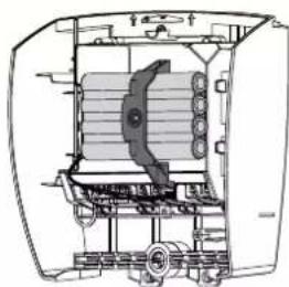
natural_image
Technical line drawing of a mechanical device with internal components (no text or symbols)4.1 Voetgangersopening
The image is too blurry to recognize any text content.
natural_image
Mechanical device with a tool and bracket, showing a close-up of a mechanical component (no text or symbols visible)natural_image
3D diagram of a device with an open lid and internal components, showing directional arrows (no text or symbols)Steek de schroevendraaier in de gleuf en til de kap op.
●

natural_image
Close-up of a computer mouse with a small circular button and an inset showing a battery symbol (no text or labels)natural_image
Close-up of a computer mouse with an arrow pointing to the internal component (no text or symbols visible)Vervang de batterij (3 V CR 2430 of CR 2032).
6.3 Wis de instellingen
flowchart
graph LR
    A["Group 1: Radio, P1, RESET"] --> B["Group 2: Radio, P1, RESET"]
    B --> C["Group 3: Radio, P1, RESET"]
natural_image
Diagram of a two-level mechanical or electrical device labeled 'Zona 5' with no visible text or symbols on the device itself.natural_image
Illustration of a hand pressing a corner component (no text or symbols)

Solutie:
natural_image
Silhouette of a person standing inside a door with a vertical pipe inserted (no text or symbols)

Solutie:
natural_image
Line drawing of two identical door structures with vertical slats, no text or symbols present
natural_image
Simple line drawing of a doorway with a cross symbol at the center (no text or labels)Ranforturile
natural_image
Two mechanical bracket components with mounting holes, labeled 'saus' (no other text or symbols)
natural_image
Technical line drawing of a mechanical clamp or bracket assembly (no text or symbols)natural_image
Diagram showing a tool interacting with a wire and a spring, with no visible text or symbolsnatural_image
Technical line drawing of a mechanical bracket or clamp assembly (no text or symbols)natural_image
Technical line drawing of a mechanical assembly with a red arrow indicating direction (no text or symbols)natural_image
Technical line drawing of a mechanical clamp or bracket assembly (no text or symbols)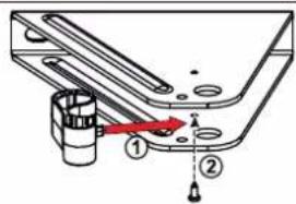
natural_image
Diagram of a balanced lever system with two supports and directional arrows indicating force or motion (no text or labels)natural_image
Technical line drawing of a mechanical assembly with no visible text or symbolsnatural_image
Technical line drawing of a mechanical assembly with a tool inserted into a cylindrical component (no text or symbols)natural_image
Technical line drawing of a mechanical component with a rod inserted, showing alignment lines (no text or symbols)natural_image
Illustration of a handheld tool with a string and two dots above it, no text or symbols presentnatural_image
Technical line drawing of a mechanical component with mounting holes and a central housing (no text or symbols)natural_image
Technical line drawing of a mechanical assembly with no visible text or symbols2

natural_image
Technical diagram showing mechanical assembly with a bracket and a close-up of a rail track component (no text or symbols)natural_image
Technical diagram showing mechanical assembly with a tool and spring mechanism (no text or symbols)flowchart
graph LR
    A["Device with rotation arrow"] --> B[" folder with arrow"]
    B --> C[" Box with arrow"]


natural_image
Diagram showing a hand holding a sensor with signal waves, and two rotating rods with arrows indicating motion (no text or symbols)natural_image
Technical diagram of an electrical device showing internal components and wiring (no text or labels)The image is too blurry to recognize any text content.
flowchart
graph LR
    A["Group 1: Radio, P1, RESET, somfy."] --> B["Group 2: Radio, P1, RESET, somfy."]
    B --> C["Group 3: Radio, P1, RESET, somfy."]
Blocarea motoarelor
Somfy Romania S.R.L.
(+4) 0374 494 418
www.somfy.ro
natural_image
Exterior view of a white computer monitor with a small screen and button (no visible text or symbols)


- Sommaire
- Solution :
- Renforts
- ▶ Vérifier la position de l'antenne
- Safety instructions 2
- Product description 6
- Prerequisites for installation
- Installation
- Commissioning and standard use 19
- Wiring the accessories 22
- Advanced parameter settings 24
- Programming the remote controls 27
- Troubleshooting guide 29
- Technical data 32
- > Safety instructions
- DANGER
- WARNING
- PRECAUTION
- CAUTION
- ▶ Important information
- ▶ Condition of the gate to be motorised
- Electrical installation
- ▶ Cable feed
- ▶ Safety instructions relating to installation of the motorisation
- ▶ Safety instructions relating to operation
- ▶ Safety instructions relating to maintenance
- Every month, check:
- ▶ About the batteries
- ▶ Recycling and disposal
- ▶ Regulations
- Risk prevention
- Identification of risk zones
- Measures to be taken to counter risks
- ZONE 2
- Solution:
- ZONE 3
- ZONE 4
- ZONE 5
- ▶ Field of application
- ▶ Presentation of the control electronics
- >Prerequisites for installation
- ▶ Pre-installation checks
- Gate
- Reinforcements
- Closing end stops on the ground
- Mechanical lock
- Pillars
- Electrical pre-equipment
- Cables required
- Cable feed
- ▶ Cables required
- Measuring the dimensions
- Recommended: dimension A is negative
- Mounting the pillar brackets
- ▶ Marking the AM and AH axes
- Drilling the pillars
- Securing the motors to the gate leaves
- Installing the control unit
- ▶ Position of the control unit
- - Installing the sealing strip
- ▶ Checking the position of the antenna
- ▶ Securing the control unit
- Connecting the motors
- Connecting to the power supply
- Switching the installation on
- Adjusting the opening stop
- Opening end stop
- Gate travel auto-programming
- Case 1: First commissioning of your motorisation
- Case 2: You have just deleted the settings
- Closing the control unit
- Standby/Reactivating the control electronics
- Completely opening and closing the gate
- Obstacle detection
- User training
- Photoelectric cells
- ▶ Installation
- ▶ Operation with photoelectric cells
- Flashing light
- ▶ Operation of the flashing light
- Battery (optional)
- ▶ Battery technical data
- Offset antenna (optional)
- Video entry phone (optional)
- Key lock (optional)
- Area lighting (optional)
- ▶ Area lighting operation
- Solar power (optional)
- Pedestrian opening
- ▶ Pedestrian opening operation
- ▶ Activating the pedestrian opening
- i
- 12
- ●
- ▶ Deactivating pedestrian opening
- Automatic closing
- ▶ Automatic closing operation
- ▶ Activating automatic closing
- ▶ Deactivating automatic closing
- 45
- The image is too blurry to recognize any text content.
- Description of the remote controls
- Adding a remote control
- ▶ 2- or 4-button remote control
- C
- ▶ 3-button remote control
- 1
- Deleting a remote control
- Assistance
- Replacing the remote control battery
- Clearing the settings
- When should I clear the settings?
- 5
- To clear the settings\*
- To clear the settings\* and the memorised remote controls/control points
- Unlocking/locking the motors
- Unlocking the motors
- 2
- Locking the motors
- Diagnostics
- Inhaltsverzeichnis
- Sicherheitshinweise
- Oplossing:
- Versterkingen
- Voetgangersopening
- Wis de instellingen
- Solutie:
- Ranforturile
- Blocarea motoarelor
- Somfy Romania S.R.L.
Brand : SOMFY
Model : SGS Line
Category : Garage door opener