PRO-77IR - Temperature sensor AREXX - Free user manual and instructions
Find the device manual for free PRO-77IR AREXX in PDF.
| Brand | AREXX |
| Model | PRO-77IR |
| Product type | Infrared temperature sensor |
| Category | Temperature sensor |
| Power supply | 2 batteries (not included, standard type) |
| Temperature range | -30°C to +80°C |
| Transmission frequency | 433 MHz |
| Transmission power | Less than 10 mW |
| Range | 20 to 40 meters (depending on environment) |
| Transmission interval | Approximately 45 seconds |
| Display functions | Temperature, sensor identifier, emissivity, empty screen |
| Adjustable emissivity | Yes, from 0.10 to 1.00 in steps of 0.05 |
| Backlight | Yes, via dedicated button |
| USB receiver included | Yes |
| Software included | Yes (Templogger on CD) |
| USB cable included | Yes |
| Compatibility | Windows (with Templogger software) |
| Splash resistance | Yes (but not waterproof) |
| Maintenance and cleaning | Clean with a dry cloth; avoid liquids |
| Safety | Do not immerse; protect in humid environments with a plastic bag |
| Spare parts and repairability | Contact AREXX after-sales service or consult www.arexx.com |
| General information | The detector measures temperature by infrared using the emissivity coefficient. Data is transmitted wirelessly to the USB receiver connected to the computer. |
Frequently Asked Questions - PRO-77IR AREXX
User questions about PRO-77IR AREXX
0 question about this device. Answer the ones you know or ask your own.
Ask a new question about this device
Download the instructions for your Temperature sensor in PDF format for free! Find your manual PRO-77IR - AREXX and take your electronic device back in hand. On this page are published all the documents necessary for the use of your device. PRO-77IR by AREXX.
USER MANUAL PRO-77IR AREXX
- General Information
- Instructions for PRO-55int and PRO66ext 18
2.1. Instructions for PRO-77ir
2.2. Instructions for PRO-PT100 -
Transmission problems
-
Communication test 24
-
Junction Box 27
natural_image
Technical line drawing of an electronic component with internal structure and external housing (no text or symbols)Strom Vertärkung (Parameter 1):
Referenz Temperature 1:
Abb. 11. Repeater Konfiguration
5. ANSCHLUSSKASTEN
- First please read this complete manual before you continue.
- More manuals can be found on the CD and in our Multilogger Software HELP FUNCTION.
- Install the software, please refer to the manual on the CD-ROM! Always check on www.arexx.com if you have the latest software version at hand.
- Connect the USB receiver to the computer.
- Start the program.
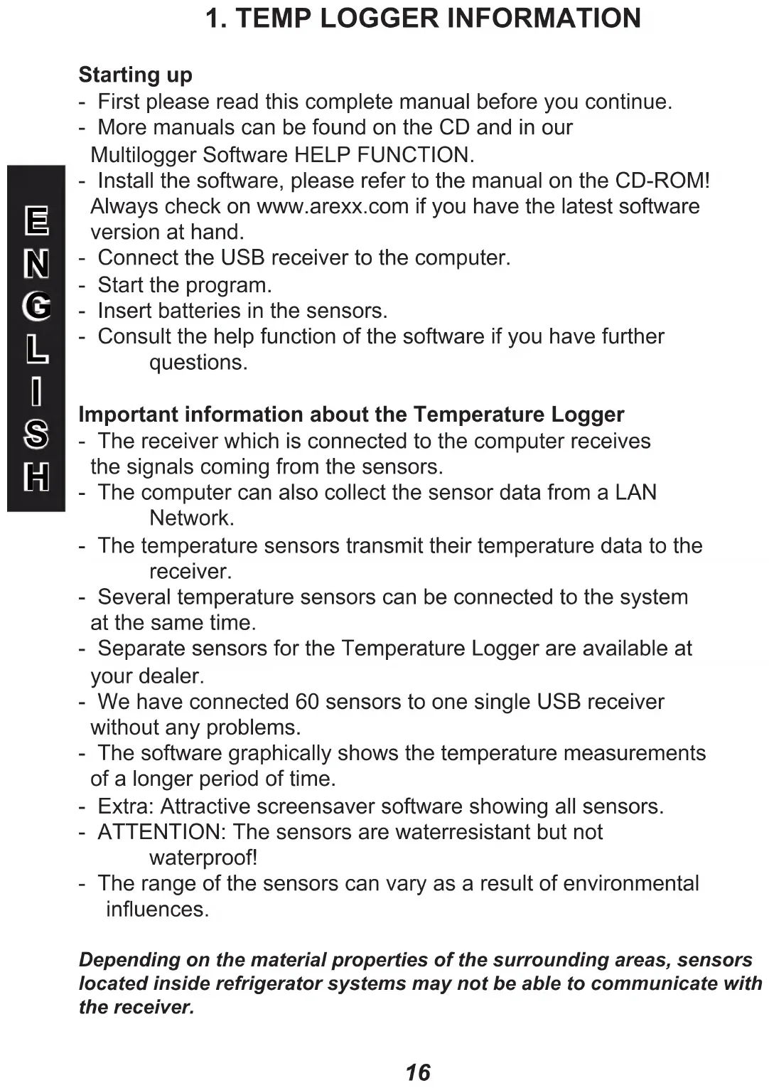
- Insert batteries in the sensors.
- Consult the help function of the software if you have further questions.
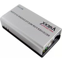
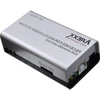
Important information about the Temperature Logger
- The receiver which is connected to the computer receives the signals coming from the sensors.
- The computer can also collect the sensor data from a LAN Network.
- The temperature sensors transmit their temperature data to the receiver.
- Several temperature sensors can be connected to the system at the same time.
- Separate sensors for the Temperature Logger are available at your dealer.
- We have connected 60 sensors to one single USB receiver without any problems.
- The software graphically shows the temperature measurements of a longer period of time.
- Extra: Attractive screensaver software showing all sensors.
- ATTENTION: The sensors are waterresistant but not waterproof!
- The range of the sensors can vary as a result of environmental influences.
Depending on the material properties of the surrounding areas, sensors located inside refrigerator systems may not be able to communicate with the receiver.
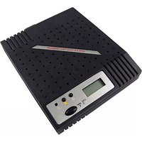
The Multilogger System consists of a Logger Software application, a USB- or LAN or receiver module and one or more sensors, each including a transmitter system.
A USB- or LAN cable connects the receiver to the computersystem or to the LAN network. The Logger application can synchronize the sensor data from several receivers.
For the Multilogger system many different sensors are already available. The sensors can measure temperature, humidity and CO2
The Multilogger application at the computer displays all sensor data, which have been transferred by temperature sensors to the receiver.
Temperature sensors continuously register temperature and report new values to the USB-receiver at intervals of ca. 45 seconds.
Each sensor in the sensorlist reports the date and time stamp for the most recent measurement data set. The right side window displays a continuous curve for the registered temperature for the selected sensor.
Sensors and receiver use a wireless communication system, working at 433MHz. This frequency is freely available for communication at transmitting powers under 10 milliwatts.
Depending on surrounding building constructions, the allowed 10mW power level allows a transmission range of 20-40 meters inside buildings, the open field range is much higher.
Temperature sensors may be located inside or outside buildings, at any place where a registered overview of temperature curves is desired.
Unreliable signal levels may be improved substantially by slightly modifying the sensor's position or the receiver's location.
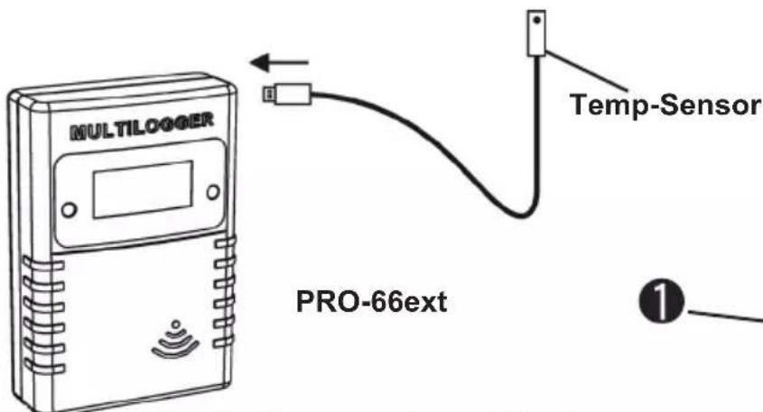
2. INSTRUCTIONS PRO-55int and PRO-66ext
Insert the batteries into the sensor.
Re the PRO-66ext start by inserting the plug of the external temperature probe.
If the plug is not properly inserted or the external probe is faulty, a 0 value will be displayed!
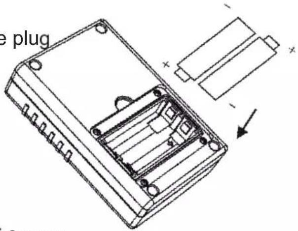
Fig. 1. Battery placement
Fig. 2. Sensor placement
After inserting the batteries, the sensor immediately transmits its first sensor data.
The PRO sensors have 2 switches:
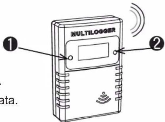
Fig. 2. Sensor switches
- Switch 1: Function switch with 3 functions
1a. Temperature data on Display
1b. Sensor number on Display
1c. No data on Display
- Switch 2: Switch for Display illumination
For extra information and software updates, please refer to our website www.arexx.com
For further questions about the product please visit our forum on www.arexx.com. On this forum you will find answers to many questions!
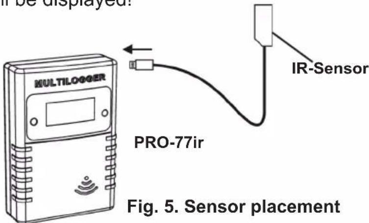
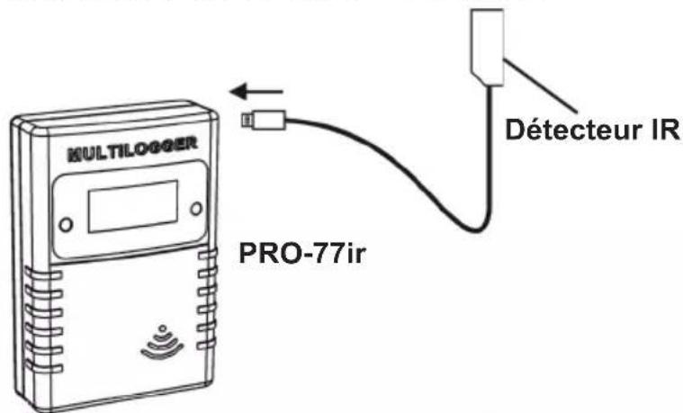
2.2. INSTRUCTIONS PRO-77ir
Connect the infrared sensor cable and insert the batteries into the infrared sensor.
Start by inserting the plug of the external temperature probe. If the plug is not properly inserted or the external probe is faulty, a 0 value will be displayed!
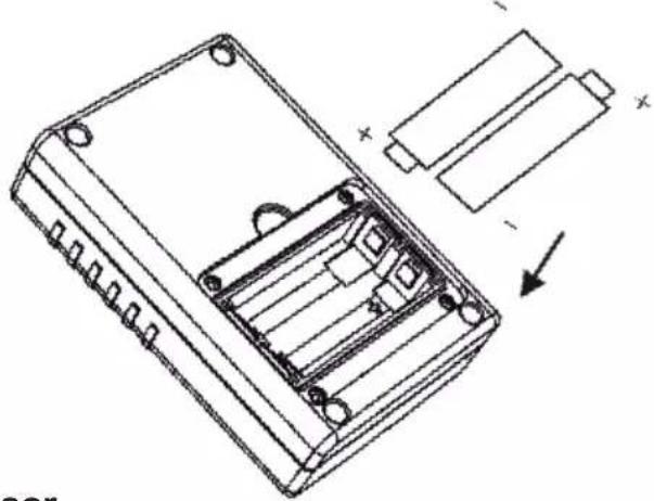
natural_image
Technical line drawing of an electronic component with internal structure and battery pack (no text or symbols)Fig. 4. Battery placement
After inserting the batteries, the sensor immediately transmits its first sensor data.
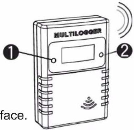
Fig. 6. Sensor switches
Infrared temperature measurement
Measuring temperature by infrared assumes knowledge about the relation between emitted infrared radiation and the temperature of the surface.
The amount of radiation is related to the material of the surface and is expressed by the emissivity coefficient .
This coefficient ranges from 0 to 1, where typically the human skin has an emissivity near 1, as most metals have a small emissivity.
Table 1 (page 53 and 54) gives some typical values for emissivity.
In order to measure the temperature of a surface, the correct coefficient value should be given. Also, notice that the surface temperature may differ from the core temperature of a (physical) body. The PRO-IR sensor uses the emissivity coefficient to calculate the temperature from received infrared radiation.
Reading and changing the emissivity coefficient
The emissivity coefficient can be read by selecting the appropriate LCD mode (with button 1).
The following modes are present:
show temperature.
The temperature is shown in degrees Celsius.
show sensor id.
The sensor id is shown in 4 digits.
This id is used for identifying the sensor.
show blank LCD screen.
In this mode the pt100 reading is reduced to a minimum. The radio data transmission remains active.
show emissivity.
The leftmost digit shows ‘E’, the rightmost 3 digits show the actual parameter value from 0.10 to 1.00.
The LCD mode can be selected by pushing the left button shortly. A next LCD mode will be selected each time the button is pushed shortly.
In order to set the emissivity value the following steps should be performed:
Select the appropriate LCD mode: show emissivity.
Push the left button a long time (approx 5 seconds) until the 'E' digit starts to blink.
Push shortly to increment the parameter value, the increment is in steps of 0.05.
When you have selected the correct value, leave the device untouched. It will jump to the show temperature mode after a few seconds. At that point the emissivity is stored into the on board non-volatile memory.
Emissivity coefficient values see page 53 and 54
2.3. INSTRUCTIONS PRO-PT100
Connect the PT100 sensor cable and insert the batteries into the PRO-PT100 sensor.
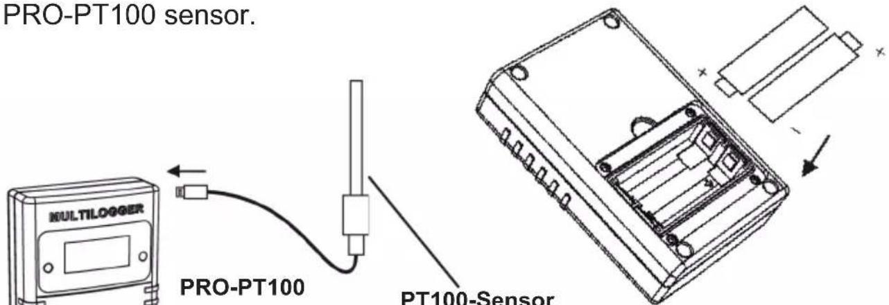
Fig. 7. Battery placement
Fig. 8. Sensor placement
After inserting the batteries, the sensor immediately transmits its first sensor data.
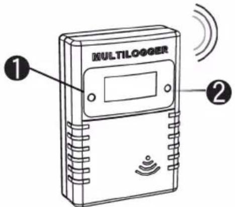
Fig. 9. Sensor switches
Calibration
Introduction
The PRO-PT100 sensor can be calibrated using a 2 point calibration scheme. At two different known reference temperatures a measurement is made with the (uncalibrated) PRO-PT100 sensor. The readings of those temperatures are set in the calibration tool. The calibration tool will give two parameter values back as return. Finally these parameter values are set in the PRO-PT100 sensor.
Details
We use two different known temperatures to calibrate the PRO-PT100. Preferably we choose the temperatures such that they are close to the outer boundaries of temperatures we expect to measure.
For example you can choose the classic combination of melting ice water and boiling water as temperature references. The readings of those temperatures are set in the calibration tool, available in the temperature logger software distribution.
The software can be found in menu Tools->"Pt100 Calibration Tool" of the logger client program. Below you find a screen shot of the tool. In this form you set the following fields:
Fig. 10.
calibrationscreen
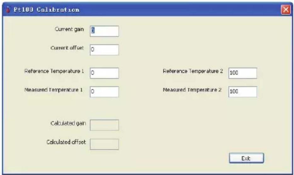
Current gain:
The current gain parameter setting used to measure the reference temperatures.
Current offset:
The current offset parameter setting used to measure the reference temperatures.
Reference Temperature 1:
The lower reference temperature value in degrees Celsius
Measured Temperature 1:
The measured temperature value in degrees Celsius
Reference Temperature 2:
The upper reference temperature value in degrees Celsius
Measured Temperature 2:
The measured temperature value in degrees Celsius
When the parameters are set, you find in the two lower fields the parameters to set in the PRO-PT100 device:
Calculated gain as parameter 1.
The calculated offset as parameter 2.
After these parameters are set, you can verify if the sensor is indicating the correct temperature for each reference. If needed you can repeat the same procedure again.
Reading and changing the parameter values
The sensor has 2 switches. The left switch is the backlight switch and the right switch is the display mode switch.
The two parameter values which are achieved after the calibration can be read by selecting the appropriate LCD mode.
The following modes are present:
show temperature. The temperature is shown in degrees Celsius.
show sensor id. The sensor id is shown in 4 digits. This id is used for identifying the sensor.
show blank LCD screen. In this mode the PT100 reading (and power consumption) is reduced to a minimum. The radio data transmission remains active.
show parameter 1. The leftmost digit shows '1', the rightmost 3 digits show the actual parameter value from -99 to +99.
show parameter 2 The leftmost digit shows '2', the rightmost 3 digits show the actual parameter value from -49 to +49.
The LCD mode can be selected by pushing the left button shortly. A next LCD mode will be selected each time the button is pushed shortly.
In order to set the parameter value the following steps should be performed:
Select the appropriate LCD mode: parameter 1 or 2.
Push the left button a long time until the '1' or '2' digit starts to blink.
Push shortly to increment the parameter value, push long for auto increment.
When you have selected the correct value, leave the device untouched. It will jump to the show temperature mode after a few seconds. At that point the parameter data is stored into the on board non-volatile memory.
Background information
The PRO-PT100 sensor determines the temperature by measuring the electrical resistance of the PT100 element. The resistance measurement is corrected linearly by the given gain and offset parameters. Finally the resistance value is converted to temperature using the DIN 60751 standard.
3. Transmission losses
Sometimes transmission losses may arise, indicated by missing temperature data in the sensor's curve display.
Data losses may be caused by:
- Problems inside the USB-receiver
- Problems in the temperature sensor module
- Problems in the signal transfer between temperature sensor module and USB-receiver
3.1. Problems inside the USB-receiver
The receiver does not register a single data signal, even if the sensor is located at a minimum distance to the receiver.
Potential problems:
- USB-cable between receiver and computer is missing or defect.
- Improper installation of the USB-module.
- Unknown software problem in the computer system.
Suggested solutions:
- Check the display window in the temperature logger display for a field in the lower left area. The field is to display the value ‘ready’ continuously. If the display intermittently displays
'RF_USB-Communication failure', the Windows operating system failed to find the USB-module.
- Remove the USB-cable, wait about ten seconds and reconnect the cable.
- Deinstall the temperature logger application software and reinstall it again.
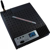
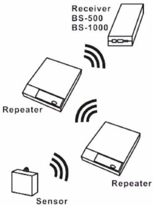
Configuration example with several repeater stations for a longer range
Fig. 11. Repeater configuration
3.2. Problems in the temperature sensor module
The receiver receives signals from sensors, but fails to register signals from one sensor in particular.
Potential problems:
- Batteries are missing or are at a low charging level
- Reversed polarity of the sensor's batteries
- The sensor's location is outside of the receiver's reception range
- Damage to the sensor (by corroded battery contacts, moisture or battery leakage)
- Problems in the radio signal communication
Suggested solutions:
- Insert fully charged batteries in the sensor and repeat the communication test (please check the polarisation of the batteries before inserting!!)
- Check the battery contacts and remove all corrosion and moisture effects.
3.3. Radio signal transfer problems
The receiver system is missing signals from one or more sensors, or only receiving a limited number of signals.
Potential problems:
- Walls or ceilings between sensor and receiver may contain metallic constructions.
- Sensors and/or receiver may be located on a metallic surface.
- Sensor or receiver are situated in locations with high humidity.
- Windows between sensor and receiver may contain several layers of glass or shielding materials or may be covered by humid moisture.
- Other 433MHz systems may be working within the 20m operating range.
- Interference or jamming signals from radio or TV transmitters.
- Electronic or electrical equipment (eg. computer equipment or microwave ovens), operating within the 2-5m operating range.
- Low power level of the sensor's batteries (see 2)
Suggested solutions:
- Modify the locations of the sensor and/or the receiver.
- Remove the interfering equipment.
4. Communication test
A simple test will check the communication channel between sensor and receiver:
- Remove the batteries from the sensor.
- If an entry already exists: remove the sensor from the temperatur logger application (using the right mouse button).
- Locate the sensor at ca. 1 m distance to the receiver.
- Put the batteries back into the sensor.
- A correctly working system will add the according sensor entry to the sensor list within 5 seconds.
Extra information and possible updates can be found on www.arexx.com (on the forum or through the Temp Logger menu).
Further questions can also be put on our forum,
see www.arexx.com
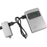
5. JUNCTION BOX
The PRO sensors are battery powered, but alternatively they (except the PRO-55int) can be powered via an external power supply. The junction box is available as a separate kit and contains:
- Jumper cable
- Junction box
- 5 volt Power adapter
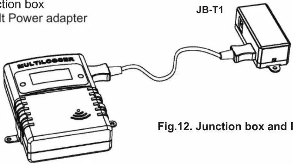
Fig.12. Junction box and PRO sensor
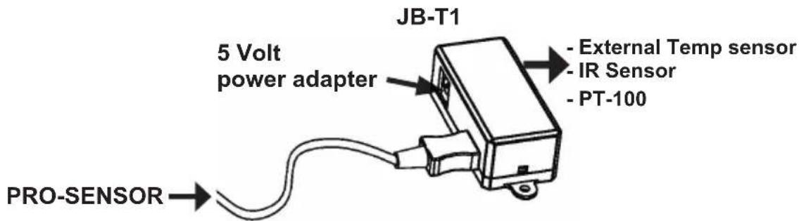
Fig. 13. Junction box connections
The box should be connected to the PRO sensor (via a jumper cable) and the 5Volt adaptor. As you can see in above drawing (junction box connections) the sensor can directly be connected to the junction box instead of the PRO sensor (ONLY PT-100 SENSOR!).
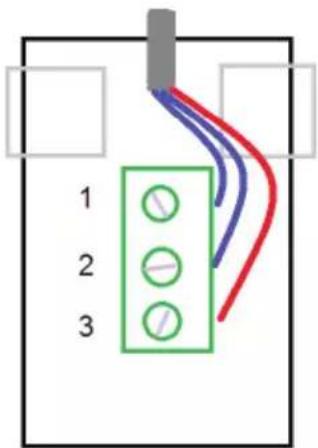
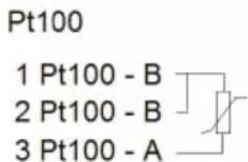

Fig. 14. Your own PT-100 connections
natural_image
Technical line drawing of an electronic component with internal structure and battery assembly (no text or symbols)Fig. 1. Insertion des piles
natural_image
Technical line drawing of an electronic component with internal structure and battery assembly (no text or symbols)Fig. 4. Insertion des piles
Current gain:
Reference Temperature 1:
Measured Temperature 1:
Measured Temperature 2:
Solutions possibles:
Solutions possibles:
Solutions possibles:
5. BOITIER DE CONNEXION
natural_image
Technical line drawing of a battery pack with internal compartments and external components (no text or symbols)Stroom versterking:
3.2. Storing in de radio-overdracht
Table 1: Typical emissivity coefficient values
| Material | Emissivity | ||
| Aluminum, polished | 0.05 | ||
| Aluminum, rough surface 0.07 | |||
| Aluminum, strongly oxidized 0.25 | |||
| Asbestos board | 0.96 | ||
| Asbestos fabric | 0.78 | ||
| Asbestos paper | 0.94 | ||
| Asbestos slate | 0.96 | ||
| Brass, dull, tarnished | 0.22 | ||
| Brass, polished | 0.03 | ||
| Brick, common | 0.85 | ||
| Brick, glazed, rough | 0.85 | ||
| Brick, refractory, rough 0.94 | |||
| Bronze, porous, rough 0.55 | |||
| Bronze, polished | 0.10 | ||
| Carbon, purified 0.80 | |||
| Cast iron, rough casting 0.81 | |||
| Cast iron, polished | 0.21 | ||
| Charcoal, powdered | 0.96 | ||
| Chromium, polished | 0.10 | ||
| Clay, fired 0.91 | |||
| Concrete | 0.54 | ||
| Copper, polished, | 0.01 | ||
| Copper, commercial burnished 0.07 | |||
| Copper, oxidized | 0.65 | ||
| Copper, oxidized to black 0.88 | |||
| Electrical tape, black plastic 0.95 | |||
| Enamel ** | 0.90 | ||
| Formica | 0.93 | ||
| Frozen soil | 0.93 | ||
| Glass | 0.92 | ||
| Glass, frosted | 0.96 | ||
| Gold, polished | 0.02 | ||
| Ice | 0.97 | ||
| Iron, hot rolled | 0.77 | ||
| Iron, oxidized | 0.74 | ||
| Iron, sheet galvanized, burnished 0.23 | |||
Material
Iron, sheet, galvanized, oxidized 0.28
| Iron, | shiny, | etched | 0.16 | |
| Iron, | wrought, | polished | 0.28 | |
| Lacquer, | Bakelite | 0.93 | ||
| Lacquer, | black, | dull | 0.97 | |
| Lacquer, | black, | shiny | 0.87 | |
| Lacquer, | white | 0.87 | ||
| Lampblack | 0.96 | |||
| Lead, | gray | 0.28 | ||
| Lead, | oxidized | 0.63 | ||
| Lead, | red, | powdered | 0.93 | |
| Lead, | shiny | 0.08 | ||
| Mercury, | pure | 0.10 | ||
| Nickel, | on | cast | iron | 0.0 |
| Nickel, | pure | polished | 0.05 | |
| Paint, silver finish** | 0.31 | |||
| Paint, | oil, | average | 0.94 | |
| Paper, | black, | shiny | 0.90 | |
| Paper, | black, | dull | 0.94 | |
| Paper, | white | 0.90 | ||
| Platinum, | pure, | polished | 0.08 | |
| Porcelain, | glazed | 0.92 | ||
| Quartz | 0.93 | |||
| Rubber | .93 | |||
| Shellac, | black, | dull | 0.91 | |
| Shellac, | black, | shiny | 0.82 | |
| Snow | 0.80 | |||
| Steel, | galvanized | 0.28 | ||
| Steel, | oxidized | strongly | 0.88 | |
| Steel, | rolled | freshly | 0.24 | |
| Steel, | rough | surface | 0.96 | |
| Steel, | rusty | red | 0.69 | |
| Steel, | sheet, | nickelplated | 0.11 | |
| Steel, | sheet, | rolled | 0.56 | |
| Tar | paper | 0.92 | ||
| Tin, | burnished | 0.05 | ||
| Tungsten | 0.05 | |||
| Water | 0.98 | |||
| Zinc, | sheet | 0.20 | ||