BS-1400GPRS - Measuring equipment AREXX - Free user manual and instructions
Find the device manual for free BS-1400GPRS AREXX in PDF.

| Product Type | Temperature recorder with GPRS communication |
| Brand | AREXX |
| Model | BS-1400GPRS |
| Radio frequency band | 433 MHz ISM |
| GPRS/GSM | 850/950/1800/1900 MHz |
| USB interface | USB 2.0, Multilogger protocol |
| Internal memory | 2 MB flash (approx. 9 days for 10 sensors) |
| Display | LCD screen with backlight |
| Power supply | Power adapter (check polarity) or USB |
| Battery type (sensors) | Alkaline batteries (check polarity) |
| Typical radio range | 20-40 meters depending on environment |
| Main functions | Recording of measurements, graphic display, alarms, SMS/email/HTTP sending |
| Max number of sensors | Up to 60 simultaneous sensors |
| Measurement interval | Approximately every 45 seconds |
| Alarm function | Built-in buzzer, configurable thresholds |
| Configuration software | Temperature Logger (downloadable from www.arexx.com) |
| Maintenance and cleaning | Keep dry, unplug if wet, do not touch components |
| Safety precautions | Check adapter polarity, avoid humidity, do not use in unfavorable conditions |
| Spare parts and reparability | Contact AREXX Engineering for repair and parts |
| Warranty | Legal warranty for manufacturing defects, excludes indirect damages |
| General information | Manual available in PDF, updates at www.arexx.com/templogger |
Frequently Asked Questions - BS-1400GPRS AREXX
User questions about BS-1400GPRS AREXX
0 question about this device. Answer the ones you know or ask your own.
Ask a new question about this device
Download the instructions for your Measuring equipment in PDF format for free! Find your manual BS-1400GPRS - AREXX and take your electronic device back in hand. On this page are published all the documents necessary for the use of your device. BS-1400GPRS by AREXX.
USER MANUAL BS-1400GPRS AREXX
- Transmission losses
- Communication test
Technical specifications 20
©2014 AREXX Engineering
Nervistaat 16
8013 RS Zwolle
The Netherlands
Tel.: +31 (0) 38 454 2028
Fax.: +31 (0) 38452 4482
E-Mail: Info@arexx.nl
On the first line, the sensor id and time of the alarm are given, together with the measurement value and unit.
The following lines are used to display the accompanying text of the rule.
| Impressum ©2014 AREXX Engineering Nervistraat 16 8013 RS Zwolle The Netherlands Tel.: +31 (0) 38 454 2028 Fax.: +31 (0) 38 452 4482 E-Mail: Info@arexx.nl | This manual is protected by laws of Copyright. Any full or partial reproduction of the contents are forbidden without prior written authorization by the European importer. Product specifications and delivery contents are subject to changes. The manual is subject to changes without prior notice. You can find free updates of this manual on http://www.arexx.com/ |
| "TL-ALU9 and Multilogger" are registered trademarks of AREXX Engineering. All other trademarks are the property of their owners. We are not responsible for the contents of external web pages that are mentioned in this manual! | |
| Information about limited warranty and responsibility | |
| The warranty granted by AREXX Engineering is limited to the replacement or repair of the BS-1400GPRS and its accessories within the legal warranty period if the default has arisen from production errors such as mechanical damage or missing or wrong assembly of electronic components except for all components that are connected via plugs/sockets. The warranty does not apply directly or indirectly to damages due to the use of the BS-1400GPRS. This excludes claims that fall under the legal prescription of product responsibility. The warranty does not apply in case of irreversible changes (such as soldering of other components, drilling of holes, etc.) of the BS-1400GPRS or its accessories or if the BS-1400GPRS is damaged due to the disrespect of this manual. The warranty is not applicable in case of disrespect of this manual! In addition, AREXX Engineering is not responsible for damages of all kinds resulting from the disrespect of this manual! Please adhere above all to the „Safety recommendations" in the BS-1400GPRS manual. IMPORTANT Prior to using this BS-1400GPRS receiver for the first time, please read this manua thoroughly up to the end. it explains the correct use and inform you about potential dangers. Moreover it contains important information that might not be obvious for all users. Important safety recommendation | |
| This module is equipped with highly sensitive components. Electronic components are very sensitive to static electricity discharge. Only touch the module by the edges and avoid direct contact with the components on the circuit board. | |
Symbols
This manual provides the following symbols:

The "Attention!" Symbol is used to mark important details. Neglecting these precautions may damage or destroy the module and/or additional components and additionally you may risk your own health or the health of other persons!

The "Information" Symbol is used to mark useful tips and tricks or background information. In this case the information is to be considered as "useful, but not necessary".
Safety recommendations
- Check the polarity of the power supply.
- Keep all products dry, when the product gets wet remove the power directly.
- Remove the power when you are not using the product for a longer period.
- Before taking the module into operation, always check it and its cables for damage.
- If you have reason to believe that the device can no longer be operated safely, disconnect it immediately and make sure it is not unintentionally operated.
- Consult an expert if you are unsure about the function, safety or connection to the module.
- Do not operate the module in unfavourable conditions.
- This module is equipped with highly sensitive components. Electronic components are very sensitive to static electricity discharge. Only touch the module by the edges and avoid direct contact with the components on the circuit board.
Normal use
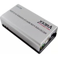
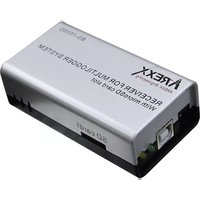
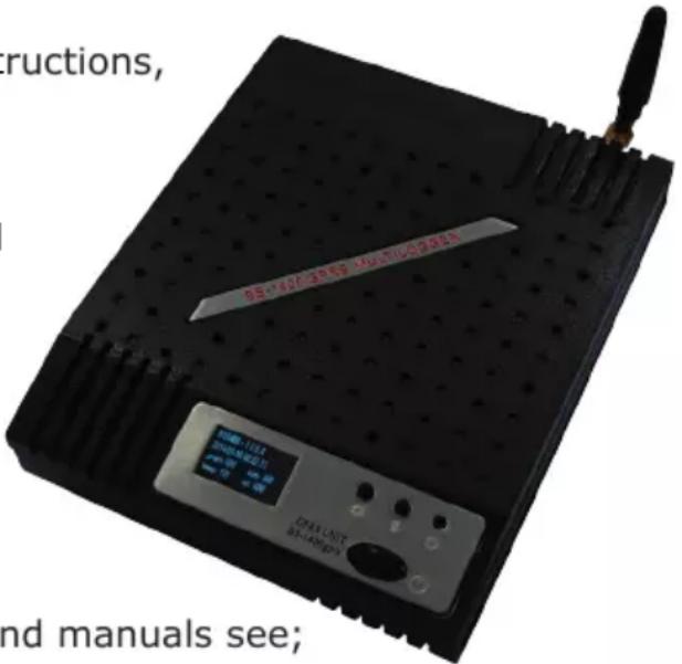
This product was developed as an receiver for the AREXX Multilogger system. It will only work together with other AREXX Multilogger sensors and products. With the BS-1400GPRS you can receive, store and transmit by GPRS the sensor data.
It may be used indoors only. The product must not get damped or wet. Also be careful with condense when you take it from a cold to an warm room, give it time to adapt to the new conditions before you use it.
Any use other than that described above can lead to damage to the product and may involve additional risks such as short circuits, fire, electrical shock etc.
Please read all the safety instructions of this manual.
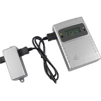
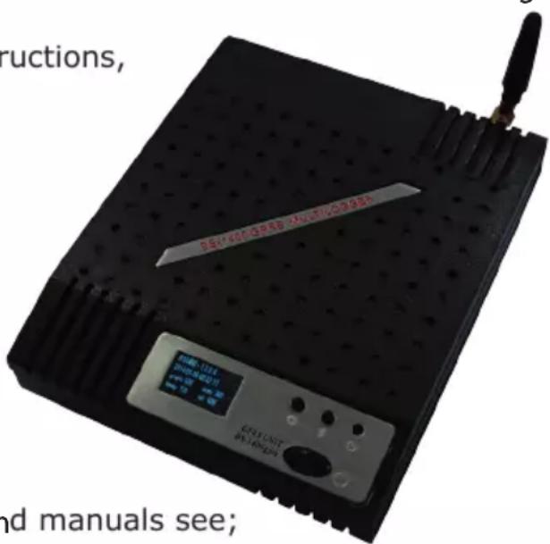
2. INTRODUCTION BS-1400GPRS TRANSCEIVER
The BS-1400GPRS records for each sensor its measurement and time stamp. These measurements are shown on the display in text and in graphical form.
The measurement data can be transmitted by GPRS (sim card is necessary) It can also be stored on an SD card (Mico-SD is necessary).
The recorded measurements are also used as input for the internal alarm control module: It checks the incoming measurements against the given rules. Depending on the condition given in the rule, an alarm or message is generated. Rules can be constructed by the rule editor tool, which can be found in the Multilogger software as well.
When a message is generated, it can be sent to a web service using HTTP via GPRS. The device also can generate SMS-text messages as alerts.
Furthermore, email messages (using SMTP) can be generated as well. The exact action depends on the rules defined and stored in the BS-1400. The text of a message can be customized with data tags like the actual measurement value, sensor id etc.
The BS-1400 usually operates stand alone, but it can also operate as a BS-510 base station. When connected to the Multilogger software via USB, the PC will record incoming measurement data via the BS-1400 directly.
The AREXX Multilogger sensors continuously report new values to the receiver at intervals of about 45 seconds.
Sensors and receiver use a wireless communication system, working at 433MHz. This frequency is freely available for communication at transmitting powers under 10 milliwatts.
Depending on surrounding building constructions, the allowed 10mW power level allows a transmission range of 20-40 meters.
Unreliable signal levels may be improved substantially by slightly modifying the sensor's or the receiver's location.
For the latest software, documentation and manuals see; http://www.arexx.com/templlogger
3. MANUAL BS-1400GPRS
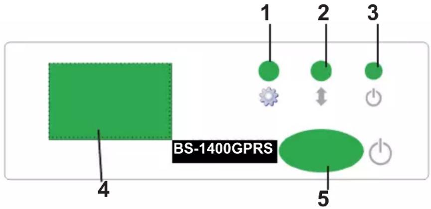
- Display mode button
2.Scroll button - Power-on indicator
- Display
- On - off switch
By pressing the display-mode button (1) different display modes can be selected:
A- List of incoming measurements
B- Recent generated alarms
C- Graphical display of recent measurements
D- Result codes from executed rules
E- General settings
F-GSM status
G-SD card status
The scroll button (2) is used to scroll through the data.
Mode A displays the recent measurement data per line:
- rssi indicator: this indicates the received signal strength of the RF data signal
- sensor id: identification number of the sensor.
-time (hh:mm:ss) - measurement value
- measurement unit, depending on the actual sensor.
Mode B displays the alarm report.
On the first line, the sensor id and time of the alarm are given, together with the measurement value and unit.
The following lines are used to display the accompanying text of the rule.
Mode C displays the recent measurements in graphical form per sensor.
A graph for each sensor, will be presented it is accessible by the scroll button.
The graph shows the upper and lower boundary, the sensor id and unit. Also a simple timescale is shown. The range of the graph is set in the general setting section.
Mode D shows the result codes from the rules executed.
The first column shows the rule number, the second column the device id, the third column is the time of execution and the fourth column is the resultcode of the rule. Generally the result code is derived from the receiving server. A http request will return 200 when ok, a SMTP server will return 250 when the email is queued successfully.
Mode E shows the model and firmware version, the actual date and time, and the actual general setting-values.
The setting-values can be changed by the BS-1200 configuration tool.
graph: the time between 2 data points in seconds. There are 24 data points shown per graph. This value defines the total time-span of the graph.
beep: duration of the buzzer in seconds. The buzzer will turn on when an alarm is set and turn off when the user presses button (1) or (2), or when the buzzer is active for more than this duration.
scrn: display time-out in seconds. If no button is pressed, the display will turn off after this period of time.
rpt: repeat alarm time in seconds. The alarm is repeated after this period of time if the alarm was left unconfirmed.
Mode F shows the GSM status.
The first line displays the general status of execution:
- idle, http, smtp, sms etc
The second line shows the PIN status: accepted (ok), error
The third line shows the name of the actual telecom-network operator.
Mode G displays the SD card status.
The total size of the card, and the free space on the card.
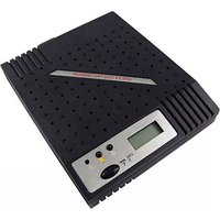
4. BS-1400 CONFIGURATION TOOL
To program the BS1400 we use a tool in the Multilogger software, you can find it in the tools menu. The general settings of the BS1400 can be inspected and changed by this tool.
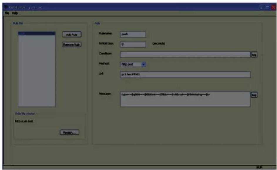
Screen 1. Configuration Tool
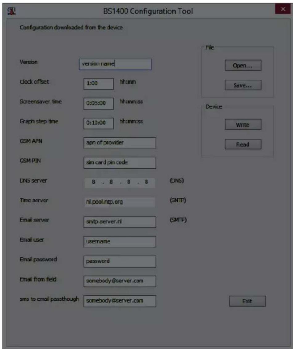
With the 'read' button the current settings are read from the device. With the 'write' button the given parameters are stored into the device. The open button loads a configuration from file. The save button lets you save the current configuration.
The following parameters can be set:
Version: The current version name given to this set of parameters
Clock offset: The internal clock is set by the PC to UTC time. To convert the displayed time to local time this offset is used. Also several messaging tags show local time.
Screensaver time (scrn): display time-out. If no button is pressed, the display will turn off after this period of time.
Graph step time (graph): the time between 2 data points in seconds. There are 24 data points shown per graph. This value defines the total timespan of the graph.
The following two fields are used to access your telecom network via your SIM card.
GSM APN: The APN as specified by your telecom provider
GSM PIN: The pincode for your SIM card. Note: the BS1400 cannot change the pin code on the SIM card. You have to use a telephone to do so if necessary. Both entries can be found on the SIM card data.
DNS Server: When you use named addresses, a DNS server is necessary. For example IP address 8.8.8.8 directs to the Google DNS servers. Note; you need a server that is available on the internet, your local router address is not accessible from the BS1400.
Time server: A URL specifying the SNMP time server. The BS1400 will synchronize its real time clock to this server.
Email server: An url to the smtp server you can use to send emails. Note: TLS/SSL is not supported.
Email user: The user-name for accessing the email server
Email password: The user-password for accessing the email server
Email from field: The email message is composed using the rule details and using this field to list the from field in the email message.
SMS to email pass-through: When SMS messages are received on the BS1400, these messages can be passed through as email to this recipient. This can be useful in order to pass provider generated SMS messages. When an SMS is passed, it is removed from the sim card.
5. Rules
The BS1400 contains messenger functionality
The BS1400 receives measurement data from sensors and checks each measurement to the rules defined. A rule can also be checked on a timer event. A rule is a condition and an action definition. The condition is evaluated against the measurement if the evaluation results 'true', the defined action is performed. The rules are stored in a file that can be uploaded to the BS1400 via USB.
Rules can be defined using the rule-editor, available from the Multilogger software package (see www.arexx.com)
The rule file can be uploaded via USB, using the rule editor or the config-upload tool.
6. Rule Editor
The Rule Editor is a tool to create a "rule" file that is used by the BS1400 to control the built-in Messenger functions. The Messenger function allows the start of one or more actions based on an incoming measured value, if its associated condition is met.
The available actions are the transmission of an e-mail, the transmission of an HTTP request, an SMS text message and the triggering of a built-in buzzer.
Following parameters are required depending on the type of action:
For an e-mail:
Name of the rule
Time lock for the rule
Condition for the rule
E-mail address
- Subject of the rule
E-mail message
For an HTTP Request:
Name of the rule
Time lock for the rule
Condition for the rule
- HTTP request type: GET or POST
- HTTP request URL
- HTTP Request message
For an SMS:
Name of the rule
Time lock for the rule
Condition for the rule
SMS phone number
SMS text message
For the buzzer:
Name of the rule
Time lock for the rule
Condition for the rule
The inhibit time of the rule defines the number of seconds during which the rules remain inactive after the execution of an action.
The condition for a rule is a logic function that is evaluated in the context of the incoming measurement. The measured value and the related attributes are used as variables.
Following variables are available:
| Variable Description | |
| v Measured value | |
| q Sensor type | 1 = Temperature (°C), 3 = RH% (‰), 5=CO2 (ppm) |
| i Identification | number of the sensor |
| r rssi-value (dBm) | |
| h Indication of the hours in the time indication of the measurement | |
| m Indication of the minutes in the time indication of the measurement | |
| s Indication of the seconds in the time indication of the measurement | |
| Y Indication of the year in the time indication of the measurement | |
| M Indication of the month in the time indication of the measurement | |
| d Indication of the day in the time indication of the measurement | |
| S Measurement time in seconds since 1-1-2000 UTC | |
| c Day of the week at the time of measurement (0=Sunday, 1=Monday...) | |
| a(len) Current running average value (len = Length in seconds) | |
| b(len) Current running minimum value (len = Length in seconds) | |
| e(len) Current running maximum (len = Length in seconds) | |
| p(dt) Previous value. If dt=0, then the previous measurement value is given, otherwise, the interpolated value at the moment of dt seconds back in time is given. | |
Except for the S , all time indications are expressed in UTC under consideration of the time zone offset indication in the configuration.
The time indication S is expressed in UTC.
The condition is structured like a logic expression. Following logical comparison operators can be used for the definition: (<, <=, >, >=, <=) and ! =) , as well as the logical operators AND (&), OR(||) and NOT(!). Also the arithmetic operations + , - , *, / and % (modulo) can be used. Moreover the expression can be organised with brackets ''('' and '') .
Examples:
| Expression Description | |
| v<10 is true as soon as the measurement goes below the value 10 . | measurement goes below the value 10 . |
| v<10 && i=8297 | is true as soon as the measurement for sensor 8297 goes below the value 10 . |
| (v<-10 || v>10)&&c==0 | is true as soon as the measurement goes below the value -10 or above10 and the day of the week is a Sunday. |
The HTTP-report, the e-mail report and the subject line for the e-mail are text fields that can be fitted with variables. The value of a variable will be replaced by text when the message text is set up.
The list of variables is:
| Variable | Description |
| v Measured value | |
| q Sensor type 1 = Temperature (°C), 3 = RV% (%), 5 = CO2 (ppm) | |
| i Identification number of the sensor | |
| r rssi-value (signal level value in dBm) | |
| h Indication of the hours in the time indication of the measurement | |
| m Indication of the minutes in the time indication of the measurement | |
| s Indication of the seconds in the time indication of the measurement | |
| Y Indication of the year in the time indication of the measurement | |
| M Indication of the month in the time indication of the measurement | |
| D Indication of the day in the time indication of the measurement | |
| S Measurement time in seconds since 1-1-2000 UTC | |
| w Missing; Time when the latest measured value has not been transmitted to the http server. Is required for the update of the temp-logger. | |
| t time string; Time of measurement in the format: hh:mm:ss | |
| d date string; Date of the measurement in the short date format | |
| p(dt) Previous value. If dt=0, then the previous measurement value is given, otherwise, the interpolated value at the moment of dt seconds back in time is given. | |
| XXml data; generates an xml list of the most recent measurements. To be used in conjunction with the timed rule type. The xml format is the same as the output from the data.xml page (see below). | |
Except for the X,w and $S, all time indications are expressed in UTC under consideration of the time zone offset indication in the config page screen Time server.
The time indications X, w and S are expressed in UTC (seconds since 1-1-2000).
The HTTP request message is url-encoded. This means that non-alphanumeric characters are converted into %hh-strings where „hh" represents a hexadecimal figure. The lines &&' and==' are an exception: these are converted into &', and=' respectively. The message for the HTTP request is transmitted via the request header POST, or else added to the URL of the GET request. In this case, the separating sign `?' is added between the URL and the message.
Example of a message:
id==i&&value==v
In this example, a web server is programmed to decode the indicated string in two parameters id' andvalue'. This method allows to supply up-to-date data from the BS1000 to a web page without a running a PC.
This method is also used for the update of the Temperature Logger.
1. Transmission losses
Sometimes transmission losses may arise, indicated by missing temperature data in the sensor's curve display.
Data losses may be caused by:
- Problems inside the transceiver
- Problems in the sensor module
- Problems in the signal transfer between temperature sensor module and transceiver
1.1. Problems inside the transceiver
The transceiver does not register a single data signal, even if the sensor is located at a minimum distance to the receiver.
Potential problems:
- USB-cable between receiver and computer is missing or defective
- Improper installation of the USB driver
- Unknown software problem in the computer system
- Internal battery is empty (replace the battery)
Suggested solutions:
- Check the display window in the temperature logger display for a field in the lower left area. The field is to display the value 'ready' continuously. If the display intermittently displays 'RF_USB-Communication failure', the Windows operating system failed to find the USB-module.
- Remove the USB-cable, wait about ten seconds and reconnect the cable.
- Deinstall the temperature logger application software and reinstall it again.
Please check the internal clock battery (Type CR2032) The lifetime of the battery is about 5 years!
1.2. Problems in the temperature sensor module
The receiver receives signals from sensors, but fails to register signals from one sensor in particular.
Potential problems:
- Batteries are missing or are at a low charging level
- Reversed polarity of the sensor's batteries
- The sensor's location is outside of the receiver's reception range
- Damage to the sensor (by corroded battery contacts, moisture or battery leakage)
- Problems in the radio signal communication
Suggested solutions:
- Insert fully charged batteries in the sensor and repeat the communication test (please check the polarisation of the batteries before inserting!!)
- Check the battery contacts and remove all corrosion and moisture effects.
Technical details
Type: BS1400GPRS
Radio: ISM 433MHz, Multilogger RF-protocol
USB: USB 2.0, Multilogger USB-protocol
SIM: GSM/GPRS edge 850/950/1800/1900 MHz
Supply: 12V DC / 2000mA
RTC battery: CR2032 3V
SD card: micro SD (SD, SDHC)
SIM card
Internal memory: 2MB data-flash (about 9 days for
10 sensors, 18 days for 5 sensors, etc.)
Software: http://www.arexx.com
Extra information and possible updates can be found on www.arexx.com
1.3. Radio signal transfer problems
The receiver system is missing signals from one or more sensors, or only receiving a limited number of signals.
Potential problems:
- Walls or ceilings between sensor and receiver may contain metallic constructions.
- Sensors and/or receiver may be located on a metallic surface
- Sensor or receiver are situated in locations with high humidity
- Windows between sensor and receiver may contain several layers of glass or shielding materials or may be covered by humid moisture.
- Other 433MHz systems may be working within the 20m operating range
- Interference or jamming signals from radio or TV transmitters
- Electronic or electrical equipment (eg. computer equipment or magnetrons), operating within the 2-5m operating range
- Low power level of the sensor's batteries (see 2)
Suggested solutions:
- Modify the locations of the sensor and/or the receiver
- Remove the interfering equipment
2. Communication test
A simple test will check the communication channel between sensor and receiver:
- Remove the batteries from the sensor
- If an entry already exists: remove the sensor from the temperatur logger application (using the right mouse button)
- Locate the sensor at ca. 1 m distance to the receiver
- Insert the batteries in the sensor
- A correctly working system will add the according sensor entry to the sensor list within 5 seconds.
Mode F shows the GSM status.
The first line displays the general status of execution:
- idle, http, smtp, sms etc
The second line shows the PIN status: accepted (ok), error
The third line shows the name of the actual telecom-network operator.
Mode G displays the SD card status, the total size of the card, and the free space on the card.
-idle, http, smtp, sms etc
Screensaver time (scrn): display time-out. If no button is pressed, the display will turn off after this period of time.
The following two fields are used to access your telecom network via your SIM card.
Alimentation: 12V DC / 2000mA
Pile RTC: CR2032 3V
Carte SD: micro SD (SD, SDHC)
The BS-1400GPRS records for each sensor its measurement and time stamp. These measurements are shown on the display in text and in graphical form.
The measurement data can be transmitted by GPRS (sim card is necessary) It can also be stored on an SD card (Mico-SD is necessary).
The recorded measurements are also used as input for the internal alarm control module: It checks the incoming measurements against the given rules. Depending on the condition given in the rule, an alarm or message is generated. Rules can be constructed by the rule editor tool, which can be found in the Multilogger software as well.
When a message is generated, it can be sent to a web service using HTTP via GPRS. The device also can generate SMS-text messages as alerts. Furthermore, email messages (using SMTP) can be generated as well. The exact action depends on the rules defined and stored in the BS-1400. The text of a message can be customized with data tags like the actual measurement value, sensor id etc.
The BS-1400 usually operates stand alone, but it can also operate as a BS-510 base station. When connected to the Multilogger software via USB, the PC will record incoming measurement data via the BS-1400 directly.
The AREXX Multillogger sensors continuously report new values to the receiver at intervals of about 45 seconds.
Sensors and receiver use a wireless communication system, working at 433MHz. This frequency is freely available for communication at transmitting powers under 10 milliwatts.
Depending on surrounding building constructions, the allowed 10mW power level allows a transmission range of 20-40 meters.
Unreliable signal levels may be improved substantially by slightly modifying the sensor's or the receiver's location.
For the latest software, documentation and manuals see; http://www.arexx.com/templogger
3. MANUAL BS-1400GPRS
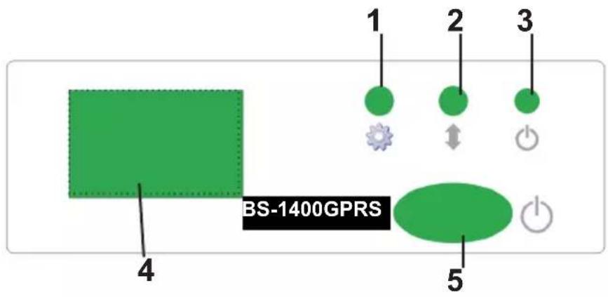
- Display mode button
2.Scroll button - Power-on indicator
- Display
- On - off switch
By pressing the display-mode button (1) different display modes can be selected:
A- List of incoming measurements
B-Recent generated alarms
C- Graphical display of recent measurements
D- Result codes from executed rules
E- General settings
F-GSM status
G-SD card status
- idle, http, smtp, sms etc
For an HTTP Request:
Following variables are available:
| Variable Desciption | |
| v Measured value | value |
| q Sensor type | 1 = Temperature (°C), 3 = RH% (%, 5=CO2 (ppm) |
| i Identification | number of the sensor |
| r rssi-value (d Bm) | |
| h Indication of | the hours in the time indication of the measurement |
| m Indication of | of the minutes in the time indication of the measurement |
| s Indication of | the seconds in the time indication of the measurement |
| Y Indication of | the year in the time indication of the measurement |
| |M Indication of | the month in the time indication of the measurement |
| D Indication of | the day in the time indication of the measurement |
| S Measurement | time in seconds since 1-1-2000 UTC |
| c Day of the week | week at the time of measurement (0=Sunday, 1=Monday...) |
| a(len) Current | running average value (len = Length in seconds) |
| b(len) Current | running minimum value (len = Length in seconds) |
| e(len) Current | running maximum (len = Length in seconds) |
| $p(dt) Previous | value. If dt=0, then the previous measurement value is given, otherwise, the interpolated value at the moment of dt seconds back in time is given. |
Except for the S , all time indications are expressed in UTC under consideration of the time zone offset indication in the configuration.
The time indication S is expressed in UTC.
The condition is structured like a logic expression. Following logical comparison operators can be used for the definition: (<, <=, >, >=, <=, <=) , as well as the logical operators AND (&), OR(||) and NOT(!). Also the arithmetic operations + , -, *, / and % (modulo) can be used. Moreover the expression can be organised with brackets ''('' and '' "
Examples:
| Expression Description | |
| v<10 is true as soon as the measurement goes below the value 10 . | measurement goes below the value 10 . |
| v<10 && i=8297 | is true as soon as the measurement for sensor 8297 goes below the value 10 . |
| (v<-10 || v>10)&&c==0 | is true as soon as the measurement goes below the value -10 or above10 and the day of the week is a Sunday. |
The HTTP-report, the e-mail report and the subject line for the e-mail are text fields that can be fitted with variables. The value of a variable will be replaced by text when the message text is set up.
The list of variables is:
| Variable | Description |
| v Measured value | |
| q Sensor type 1 = Temperature (°C), 3 = RV% (%), 5 = CO2 (ppm) | |
| i Identification number of the sensor | |
| r rssi-value (signal level value in dBm) | |
| h Indication of the hours in the time indication of the measurement | |
| m Indication of the minutes in the time indication of the measurement | |
| s Indication of the seconds in the time indication of the measurement | |
| Y Indication of the year in the time indication of the measurement | |
| M Indication of the month in the time indication of the measurement | |
| D Indication of the day in the time indication of the measurement | |
| S Measurement time in seconds since 1-1-2000 UTC | |
| w Missing; Time when the latest measured value has not been transmitted to the http server. Is required for the update of the temp-logger. | |
| t time string; Time of measurement in the format: hh:mm:ss | |
| d date string; Date of the measurement in the short date format | |
| p(dt) Previous value. If dt=0, then the previous measurement value is given, otherwise, the interpolated value at the moment of dt seconds back in time is given. | |
| XXml data; generates an xml list of the most recent measurements. To be used in conjunction with the timed rule type. The xml format is the same as the output from the data.xml page (see below). | |
Except for the X,w and $S, all time indications are expressed in UTC under consideration of the time zone offset indication in the config page screen Time server.
The time indications X, w and S are expressed in UTC (seconds since 1-1-2000).
The HTTP request message is url-encoded. This means that non-alphanumeric characters are converted into %hh-strings where „hh" represents a hexadecimal figure. The lines &&' and==' are an exception: these are converted into &', and=' respectively. The message for the HTTP request is transmitted via the request header POST, or else added to the URL of the GET request. In this case, the separating sign `?' is added between the URL and the message.
Example of a message:
id = \ i&&value = \ v
In this example, a web server is programmed to decode the indicated string in two parameters id' andvalue'. This method allows to supply up-to-date data from the BS1000 to a web page without a running a PC.
This method is also used for the update of the Temperature Logger.
1. Storingen
Supply: 12V DC / 2000mA
RTC battery: CR2032 3V
SD card: micro SD (SD, SDHC)
Internal memory: 2MB data-flash (about 9 days for 10 sensors, 18 days for 5 sensors etc)
Software: http://www.arexx.com