PRO-CO2 - Measuring equipment AREXX - Free user manual and instructions
Find the device manual for free PRO-CO2 AREXX in PDF.

| Product Type | Wireless CO2 and Temperature Sensor |
| Brand | AREXX |
| Model | PRO-CO2 |
| Usage | Measurement and recording of CO2 and temperature as part of the Multilogger system |
| CO2 Measurement Range | 400 to 2000 ppm |
| CO2 Accuracy | ±40 ppm + 2% of reading up to 1250 ppm at 22°C |
| Temperature Range | -30°C to +80°C |
| Temperature Accuracy | ±0.5°C to 1°C |
| Transmission Frequency | 433 MHz |
| Range | Approximately 50 m in open field |
| Power Supply | 6-7 V DC power adapter (included) |
| Display | Backlit LCD with CO2 and temperature display |
| Main Functions | Continuous CO2 and temperature measurement, wireless transmission to USB receiver, auto-calibration (ABC Logic), display of values and probe number |
| CO2 Sensor Type | NDIR (Non Dispersive Infrared) |
| Auto-calibration | Yes, via ABC Logic algorithm (triggers after 24h, requires an environment where CO2 reaches ~400 ppm 3 times in 14 days) |
| Operating Conditions | 0°C to 50°C, 15% to 95% RH non-condensing |
| Dimensions (estimated) | 120 x 80 x 30 mm |
| Weight (estimated) | 200 g |
| Maintenance and Cleaning | Clean with a soft, dry cloth. Avoid excessive moisture. |
| Safety | Do not expose to water or condensing humidity. Use only the provided adapter. |
| Spare Parts and Repairability | Contact the manufacturer for spare parts. Repair by a qualified technician. |
| General Information | Multilogger software required (latest version). Download at www.arexx.com/templogger. |
Frequently Asked Questions - PRO-CO2 AREXX
User questions about PRO-CO2 AREXX
0 question about this device. Answer the ones you know or ask your own.
Ask a new question about this device
Download the instructions for your Measuring equipment in PDF format for free! Find your manual PRO-CO2 - AREXX and take your electronic device back in hand. On this page are published all the documents necessary for the use of your device. PRO-CO2 by AREXX.
USER MANUAL PRO-CO2 AREXX
- General Information 13
- Instructions for PRO-CO2 15
- Transmission loss 19
- Communication test 21
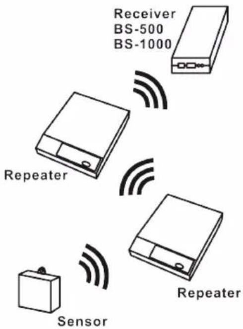
Abb. 3. Repeater Konfiguration
1. TEMP LOGGER INFORMATION
Starting up
- First please read this complete manual before you continue.
- More manuals can be found on the CD and in our Multilogger Software HELP FUNCTION.
- Install the software, please refer to the manual on the CD-ROM! Always check on www.arexx.com if you have the latest software version at hand.
- Connect the USB receiver to the computer.
- Start the program.
- Insert batteries in the sensors.
- Consult the help function of the software if you have further questions.
Important information about the Temperature Logger
- The receiver which is connected to the computer receives the signals coming from the sensors.
- The computer can also collect the sensor data from a LAN Network.
- The temperature sensors transmit their temperature data to the receiver.
- Several temperature sensors can be connected to the system at the same time.
- Separate sensors for the Temperature Logger are available at your dealer.
- We have connected 60 sensors to one single USB receiver without any problems.
- The software graphically shows the temperature measurements of a longer period of time.
- Extra: Attractive screensaver software showing all sensors.
- ATTENTION: The sensors are waterresistant but not waterproof!
- The range of the sensors can vary as a result of environmental influences.
Depending on the material properties of the surrounding areas, sensors located inside refrigerator systems may not be able to communicate with the receiver.
CHECK ALWAYS FOR THE LATEST LOGGER SOFTWARE !!!
www.arexx.com/templogger
The Multilogger System consists of a Logger Software application, a USB- or LAN or receiver module and one or more sensors, each including a transmitter system.
A USB- or LAN cable connects the receiver to the computersystem or to the LAN network. The Logger application can synchronize the sensor data from several receivers.
For the Multilogger system many different sensors are already available. The sensors can measure temperature, humidity, CO2 and also log a voltage or open or closed switch.
The Multilogger application at the computer displays all sensor data, which have been transferred by temperature sensors to the receiver.
Temperature sensors continuously register temperature and report new values to the USB-receiver at intervals of ca. 45 seconds.
Each sensor in the sensorlist reports the date and time stamp for the most recent measurement data set. The right side window displays a continuous curve for the registered temperature for the selected sensor.
Sensors and receiver use a wireless communication system, working at 433MHz. This frequency is freely available for communication at transmitting powers under 10 milliwatts.
Depending on surrounding building constructions, the allowed 10mW power level allows a transmission range of 20-40 meters inside buildings, the open field range is much higher.
Temperature sensors may be located inside or outside buildings, at any place where a registered overview of temperature curves is desired.
Unreliable signal levels may be improved substantially by slightly modifying the sensor's position or the receiver's location.
2. INSTRUCTIONS PRO-CO2
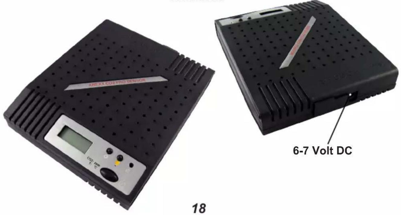
Connect the external 6-7 Volt power from the DC power adapter to the PRO-CO2 and switch on the device.
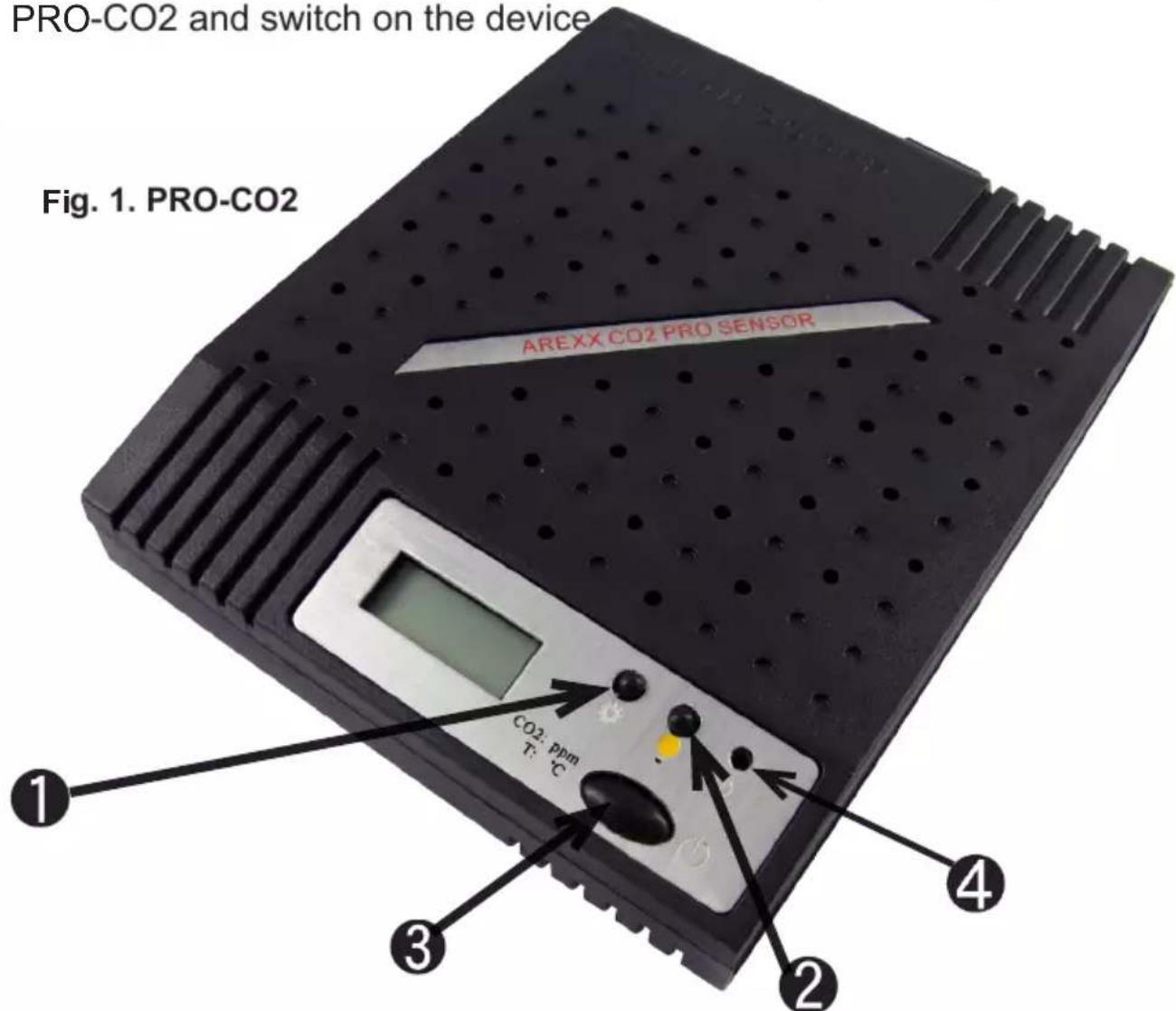
After switching on the device the LED (4) will light up and the sensor immediately transmits its first sensor data.
The PRO-CO2 Sensor has 3 switches:
- Switch 1: Function switch with 3 functions:
1a. Display shows temperature data
1b. Display shows sensor number
1c. Display shows no data
-
Switch 2: Switch for Display illumination
-
Switch 3: ON/OFF
INTRODUCTION AREXX PRO-CO2 Sensor
The PRO-CO2 Sensor is a CO2 and temperature sensor designed to be used in combination with our AREXX MULTILOGGER-System for permanent monitoring of the CO2-level and temperature. Special features for this sensor system are the wireless data-link and the frequent CO2 data which can be logged on your PC. The CO2 sensor's quality is highly professional with a GE selfcalibrating CO2 module providing highly accurate ppm-levels (in which the shortcut "ppm" refers to "Parts Per Million").
Our PRO-CO2 sensor provides each 45 seconds highly accurate CO2 and temperature data which results in an excellent trend-reporting for CO2- and temperature levels.
Outdoor CO2-levels
In Europe, outdoor air will normally provide CO2-levels between 400 and 470 ppm. Of course these values depend on environmental conditions. Measurements may result in different levels between locations in villages, in cities or in forests. CO2-levels will reach higher values in industrial areas (e.g. near highways) than in nature environments. As a result, outdoor CO2-levels may fluctuate depending on environmental conditions.
Indoor CO2-levels
Optimal values for indoor CO2-levels will not exceed 800 ppm. In smog areas with high outdoor CO2-levels, this optimal value however is hard to approach. Normally with professional and very accurate CO2 level measurement we prefer an optimum by aiming at an indoor CO2-level of 1000 ppm.
As a result, standards for CO2-levels in public buildings (e.g. in schools) should refer to some absolute CO2-levels. As soon as the CO2 level indoors exceeds a value of 1000 ppm, it is advised to ventilate the room (e.g. by opening a window).
Operating instructions
Evaluation of the CO2-levels will be restricted to the most recent versions of our Logger-software only. Always check for the latest versions at our website www.arexx.com/templogger.
Connect the power and activate the sensor with the on/off switch (5). Check if the sensor number in question including the CO2 and temperature value are present in the sensor list of the temperature logger software. The first temperature or CO2 value will appear and approx. 60 seconds later its counterpart value. With help of the settings button (2), you can call the sensor data and the sensor number, the sensor number scrolls onto the display.
After powering up the sensor, it can take a little time before the specified accuracy is achieved.
Fig. 2. Frontpanel
Operating panel:
- Display
- Settings
- Display light
- Indicator light
- On/Off switch
Calibrating
The GE CO2 module is self calibrating by means of the Automatic Background Logic ('ABC Logic').
ABC Logic is a patented self calibrating technology which is developed for an environment where the CO2 level reaches the regular value (approx. 400 ppm) at least three times during 14 days.
The ABC Logic algorithm starts working after 24 hours and then adjusts its measurement result automatically.
Specification of the PRO-CO2 sensors
The CO2-Sensor is designed for environments with temperatures ranging between 0° and 50°C and for relative humidity levels between min. 0% and max. 95% non condensing.
CO2-Measurement:
Measurement range: from 400 ppm up to 2000 ppm Accuracy: @22°C when compared against a certified factory reference ±40 ppm + 2% of reading up to 1250 ppm
Response time: < 2 minutes after activating 10 minutes for maximum accuracy CO2-Sensortype: Non Dispersive Infrared (NDIR) Lifetime for the sensor: min. 10 years
Operating Conditions CO2 measurement:
- 0^ C to 50^ C
• 0 to 95% RH, non condensing
Temperature measurement:
Temperature: from -30 up to +80° Celsius, ± 0,5° respectively 1°.
Supply current: 6 to 7 Volt DC / 100mA RF-frequency: 433 MHz
Range: approximately 50 meters in free field conditions
3. Transmission losses
Sometimes transmission losses may arise, indicated by missing temperature data in the sensor's curve display.
Data losses may be caused by:
- Problems inside the USB-receiver
- Problems in the temperature sensor module
- Problems in the signal transfer between temperature sensor module and USB-receiver
3.1. Problems inside the USB-receiver
The receiver does not register a single data signal, even if the sensor is located at a minimum distance to the receiver.
Potential problems:
- USB-cable between receiver and computer is missing or defect.
- Improper installation of the USB-module.
- Unknown software problem in the computer system.
Suggested solutions:
- Check the display window in the temperature logger display for a field in the lower left area. The field is to display the value ‘ready’ continuously. If the display intermittently displays
'RF_USB-Communication failure', the Windows operating system failed to find the USB-module.
- Remove the USB-cable, wait about ten seconds and reconnect the cable.
- Deinstall the temperature logger application software and reinstall it again.
Configuration example with several repeater stations for a longer range
Fig. 3. Repeater configuration
3.2. Problems in the temperature sensor module
The receiver receives signals from sensors, but fails to register signals from one sensor in particular.
Potential problems:
- Batteries are missing or are at a low charging level
- Reversed polarity of the sensor's batteries
- The sensor's location is outside of the receiver's reception range
- Damage to the sensor (by corroded battery contacts, moisture or battery leakage)
- Problems in the radio signal communication
Suggested solutions:
- Insert fully charged batteries in the sensor and repeat the communication test (please check the polarisation of the batteries before inserting!!)
- Check the battery contacts and remove all corrosion and moisture effects.
3.3. Radio signal transfer problems
The receiver system is missing signals from one or more sensors, or only receiving a limited number of signals.
Potential problems:
- Walls or ceilings between sensor and receiver may contain metallic constructions.
- Sensors and/or receiver may be located on a metallic surface.
- Sensor or receiver are situated in locations with high humidity.
- Windows between sensor and receiver may contain several layers of glass or shielding materials or may be covered by humid moisture.
- Other 433MHz systems may be working within the 20m operating range.
- Interference or jamming signals from radio or TV transmitters.
- Electronic or electrical equipment (eg. computer equipment or microwave ovens), operating within the 2-5m operating range.
- Low power level of the sensor's batteries (see 2)
Suggested solutions:
- Modify the locations of the sensor and/or the receiver.
- Remove the interfering equipment.
4. Communication test
A simple test will check the communication channel between sensor and receiver:
- Remove the batteries from the sensor.
- If an entry already exists: remove the sensor from the temperatur logger application (using the right mouse button).
- Locate the sensor at ca. 1 m distance to the receiver.
- Put the batteries back into the sensor.
- A correctly working system will add the according sensor entry to the sensor list within 5 seconds.
Extra information and possible updates can be found on www.arexx.com (on the forum or through the Temp Logger menu).
Further questions can also be put on our forum,
see www.arexx.com
Alimentation: 6-7 Volt DC
Solutions possibles:
Solutions possibles:
Solutions possibles:
1. TEMP LOGGER INFORMATIE
Opstarten:
Nauwkeurigheid: @22°C when compared against a
certified factory reference ±40
ppm + 2% of reading up to 1250 ppm
Responsetijd: < 2 minuten operational
10
minutes
for
maxim:
CO2-Sensortype: Non Dispersive Infrared (NDIR)
Levensduur CO2 sensor: Minimaal 10 Jahre