BS-510 - Measuring equipment AREXX - Free user manual and instructions
Find the device manual for free BS-510 AREXX in PDF.

User questions about BS-510 AREXX
0 question about this device. Answer the ones you know or ask your own.
Ask a new question about this device
Download the instructions for your Measuring equipment in PDF format for free! Find your manual BS-510 - AREXX and take your electronic device back in hand. On this page are published all the documents necessary for the use of your device. BS-510 by AREXX.
USER MANUAL BS-510 AREXX
- Multilogger Information
- Manual
- Messenger 42
- Trouble shooting and transmission problems 47
- Firmware Update APENDIX 66
*NL BS-510 INFORMATIE
- Multilogger Informatie
- Handleiding 94
- Messenger 99
- Storingen 105
- Firmware Update 108 APENDIX 109
| Impressum ©2015 AREXX Engineering Nervistraat 16 8013 RS Zwolle The Netherlands Tel.: +31 (0) 38 454 2028 Fax.: +31 (0) 38 452 4482 E-Mail: Info@arexx.nl | This manual is protected by laws of Copyright. Any full or partial reproduction of the contents are forbidden without prior written authorization by the European importer. Product specifications and delivery contents are subject to changes. The manual is subject to changes without prior notice. You can find free updates of this manual on http://www.arexx.com/ |
| "BS-510 and Multilogger" are registered trademarks of AREXX Engineering. All other trademarks are the property of their owners. We are not responsible for the contents of external web pages that are mentioned in this manual! | |
| Information about limited warranty and responsibility | |
| The warranty granted by AREXX Engineering is limited to the replacement or repair of the BS-510 and its accessories within the legal warranty period if the default has arisen from production errors such as mechanical damage or missing or wrong assembly of electronic components except for all components that are connected via plugs/sockets. The warranty does not apply directly or indirectly to damages due to the use of the BS-510. This excludes claims that fall under the legal prescription of product responsibility. The warranty does not apply in case of irreversible changes (such as soldering of other components, drilling of holes, etc.) of the BS-510or its accessories or if the BS-510is damaged due to the disrespect of this manual. The warranty is not applicable in case of disrespect of this manual! In addition, AREXX Engineering is not responsible for damages of all kinds resulting from the disrespect of this manual! Please adhere above all to the „Safety recommendations" in the BS-510 manual. Please note the relevant license agreements on the CD-ROM! | |
| IMPORTANT Prior to using this BS-510 receiver for the first time, please read this manua thoroughly up to the end. it explains the correct use and inform you about potential dangers. Moreover it contains important information that might not be obvious for all users. Important safety recommendation This module is equipped with highly sensitive components. Electronic components are very sensitive to static electricity discharge. Only touch the module by the edges and avoid direct contact with the components on the circuit board. | |
Symbols
This manual provides the following symbols:

The "Attention!" Symbol is used to mark important details. Neglecting these precautions may damage or destroy the module and/or additional components and additionally you may risk your own health or the health of other persons!

The "Information" Symbol is used to mark useful tips and tricks or background information. In this case the information is to be considered as "useful, but not necessary".
Safety recommendations
- Check the polarity of the power supply.
- Keep all products dry, when the product gets wet remove the power directly.
- Remove the power when you are not using the product for a longer period.
- Before taking the module into operation, always check it and its cables for damage.
- If you have reason to believe that the device can no longer be operated safely, disconnect it immediately and make sure it is not unintentionally operated.
- Consult an expert if you are unsure about the function, safety or connection to the module.
- Do not operate the module in unfavourable conditions.
- This module is equipped with highly sensitive components. Electronic components are very sensitive to static electricity discharge. Only touch the module by the edges and avoid direct contact with the components on the circuit board.
Normal use
This product was developed as an receiver for the AREXX Multilogger system. It will only work together with other AREXX Multilogger sensors and products. With the BS-510 you can receive and store the sensor data.
It may be used indoors only. The product must not get damped or wet. Also be careful with condense when you take it from a cold to an warm room, give it time to adapt to the new conditions before you use it.
Any use other than that described above can lead to damage to the product and may involve additional risks such as short circuits, fire, electrical shock etc.
Please read all the safety instructions of this manual.
1a. MULTILOGGER SYSTEM OVERVIEW
The Multillogger system has the following features:
Long term data logging of temperature, humidity CO2 levels etc.
Generating alarms with the Messenger software
Put your sensor data into the cloud (for example www.multilogger.nl)
IoT services (switches on of equipment over a network)
Usage
The Multilogger system is used in homes, restaurants, hotels, laboratories, stores; everywhere where you want to monitor and guard temperatures, humidity etc.
The Multilogger system contains the following items;
- Wireless sensors for temperature, humidity, CO2 levels, Legionella voltage levels etc
One or more receivers - Free powerful software (Multilogger and Messenger)
- Optional SAM IoT switchbox
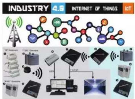
The Multilogger receives the sensor data wirelessly and stores it anywhere you want. With the free powerful Multilogger software you can analyze and export the sensor data. The free Messenger software enables you to send alarms by email.
With the LAN, WIFI and GPRS receiver you can put your sensor data into the CLOUD on your own webserver or try for free our www.multilogger.nl webserver.
Spectacular is the IoT possibility over a LAN network. The Multilogger system can communicate with our SAM -04LAN IoT switch box. With the SAM-04LAN you can switch on or off all kinds of equipment. The SAM also has several digital inputs so it can react on its environment and act according your instructions.
1b. MULTILOGGER INFORMATION
QUICK START
- Please read this manual first.
- Install the Multilogger Software
- Connect the BS-510 with the USB cable to a PC
- When sensors are active, the receive LED will blink each time it receives data.
- Start the Logger Software
The latest software is available at http://www.arexx.com/templogger
- The BS-510 receives the measurements from the sensors wirelessly.
- The temperature sensors transmit their data to the BS-510.
- Many sensors (about 60) can be connected to the system at the same time.
- Separate sensors for the Temperature Logger are available at your dealer.
- We have connected 60 sensors to one single receiver without any problems.
- The BS-510 shows the sensor measurements of a longer period of time graphically on the PC with the multilogger software.
- The range of the sensors can vary as a result of environmental influences.
- Depending on the material properties of the surrounding areas, sensor located inside refrigerator systems may not be able to communicate with the receiver.
Depending on the material properties of the surrounding areas, sensors located inside refrigerator systems may not be able to communicate with the receiver.
The latest software, documentation and manuals see: http://www.arexx.com/templogger
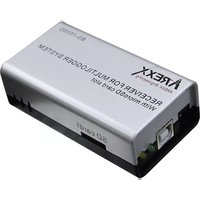
1c. INTRODUCTION BS510 WIFI TRANSCEIVER
The BS-510records for each wireless sensor its measurement and time stamp. These measurements are shown in the Multilogger software.
The recorded measurements are also used as input for the messenger alarm software which is also installed on your PC with the logger software. It checks the incoming measurements against the given rules. Depending on the condition given in the rule, an alarm or message is generated. Rules can be constructed by the rule editor tool, which can be found in the Multilogger software as well.
When a message is generated, the PC can send it to a web service using TCP/IP protocol via the WIFI/LAN network. The PC also can generate e-mail messages as alerts. Furthermore, email to SMS text messages can be generated as well. The exact action depends on the rules defined and stored in the PC. The text of a message can be customized with data tags like the actual measurement value, sensor id etc.
The BS-510 usually operates connected to a PC but it can also operate as a stand alone base station. When connected to the Multilogger software via USB, the PC will record incoming measurement data on the PS harddisk directly.
The AREXX Multilogger sensors continuously report wireless new values to the receiver at intervals of about 45 seconds. This time is fixed in the sensors and cannot be changed.
Sensors and receiver use a wireless communication system, working at 433MHz. This frequency is freely available for communication at transmitting powers under 10 milliwatts. Depending on surrounding building constructions, the allowed 10mW power level allows a transmission range of 20-40 meters.
Unreliable signal levels may be improved substantially by slightly modifying the sensor's or the receiver's location.
See also transmission losses in Chapter 4.
For the latest software, documentation and manuals see; http://www.arexx.com
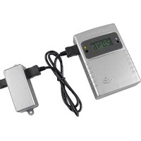
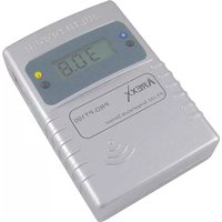
2. AREXX BS-510 Manual
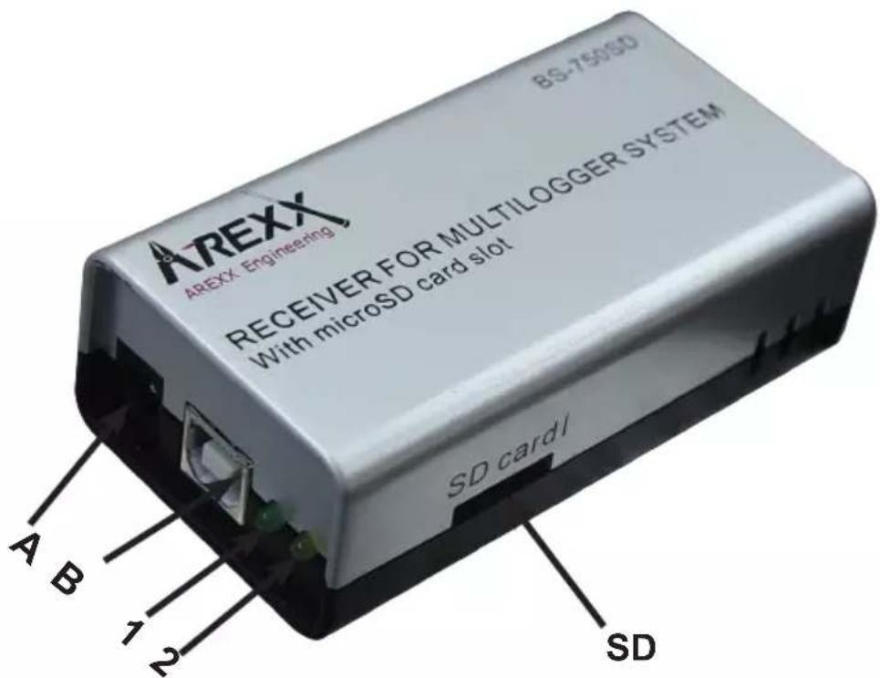
- Green receive LED
- Orange data storage LED
A. USB connector
B. DC connector
Scope of delivery BS-510 Base Station
- BS-510 Base station module
- USB cable
For the latest software, documentation and manuals see;
http://www.arexx.com
The BS-510 is a USB Multilogger receiver, the module receives measurement data from the Multilogger sensors wirelessly and prepares these data for further processing via a USB-entry at a PC. The BS-510system provides us with an internal memory flashdata-storage for measurement data during offline-periods at which the PC is disconnected.
Application sample for the BS-510S
Let us assume you already installed the Multilogger software at your PC and also inserted the batteries into your sensors. Now use the included USB-cable to connect the BS-510 device to your PC.
The very first connection the PC will ask you to install is the USB-driver for the BS-510 (RF_USB). In case the driver software has been installed correctly and the BS-510has been connected, the Multilogger software Synchronisation window will display a 'USB@x' message and the firmware's module version.
In a next step the module will transfer the sensors' measurement data to your PC. The Multilogger software will display this process at the window "sensors list", which lists the most recent data for all sensors. The Sensor list is under the Menu view.
The module will process incoming sensor data as long as it is connected to a power supply. If the PC is disconnected or switched off, the system will store data in the internal data-flash memory.
As soon as the PC-connection has been reactivated, the Multilogger software will resume the data transfer from the flash memory to the PC. This concept allows a continuous measurement data flow - even if the PC is offline from time to time.
The module also can be operated in a stand-alone mode (without being supplied from the USB-connector at a deactivated PC). In this case however, the BS-510 must be connected to an external power supply (5 up to 7.5 Volts, minimal 500mA , e.g. a universal mains power adapter).
The module signals its status by one green and one orange LED. The green LED will shortly flash as soon as the BS-510 receives a message from a sensor. The orange LED will be activated as soon as data is recorded in the internal data-flash memory, which also indicates a disconnected PC. The orange indicator will be switched off as soon as the PC-connection has been reactivated.
Radio
Sensor data will be received at the 433MHz (ISM band) radio band. The module has been equipped with an internal antenna for reception of the radio signals. In order to enable an undisturbed and reliable radio transmission the module must be installed at an optimal location by excluding deteriorating conditions such as:
metallic walls,
- armed concrete, (building) concrete with steel bars, mesh, etc.,
- armed glass, e.g. with a metallic mesh or grid
- other equipment operating in the range of a 433MHz radio-band
Radio interference may also cause a display of unknown sensors. Unexpected sensor data may be suppressed by activating the sensor filter option in the software.
USB
USB-implementations may vary from PC to PC, which mostly seems to cause some problems at connecting and disconnecting (respectively switching on and switching off) the computer. Sometimes even the disconnected PC will still provide the USB-connector with the standard amount of specified DC-power. Under such conditions the BS-510 will operate without the need for an external power supply. In other cases, in which the USB-connector does not provide DC-power, an external power supply will be needed to allow the BS-510 to collect measurement data during the offline-periods of the PC.
If you have problems re-reading the sensor data, after the stand allone mode, we suggest to turn on the PC and Templogger Software first! Then connect the USB cable again (^*) , so the sensor data of the BS-500 can be transmitted to the PC again.
(*) As different PC types have a lot of differently working USB ports problems can arise. Then werecommend to disconnect the USB cable between the BS-510 and the PC. The BS-510 receives the command to automatically start downloading if it receives the 5 Volt USB voltage from the PC. Some PC's turn the USB spanning a few times on and off during their start. This can cause data loss of the information stored in the BS-510. This can be solved when you connect the USB cable only when the PC has started completely.
Important for PC's which are turned on with a BS-510 connected: It can occur that the PC turns off the USB voltage if it goes into sleep modus (this can be changed/adjusted under Windows)! If no external voltage is connected, the BS-510 will not work anymore!
If the PC awakes from its sleep modus, the USB voltage can be turned on and off shortly several times, so the BS-510 data can be lost.
Above problems only occur with some PC models!
External power supply
The module will operate in stand-alone mode as long as an external power supply delivers the required DC-power. Data will be stored in the internal data-flash memory. As soon as the DC-power is being removed and the module switches off, a tiny set of the most recent data records may be missing in the internal data-flash memory. This effect is caused by a data-cache (intermediate storage) method, in which data is being collected before writing a complete record set to the flash memory.
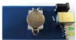
Internal real-time clock
The BS-510 module uses an internal clock (RTC) to supply measurement data with a time-stamp. With the help of a small battery (a button cell type: CR2032) this clock will also be operating uninterruptedly in a switched-off module. The clock will be synchronized by the Multilogger software as soon as a data link has been established.
If the clock restarts – for instance to be caused by an empty button cell the missing time-stamp prevents the system to record new data.
The error will cause both indicator LEDs to flash simultaneously.
The error status may be removed by connecting the module to the PC in order to synchronize the module with the Multilogger software. The software will synchronize the clocks, which allows the Multilogger process to restart further logging.
It is easy to replace the button cell battery. The button cell can be found at the printed circuit board, which is made accessible by opening both halves of the BS-510 compartment.
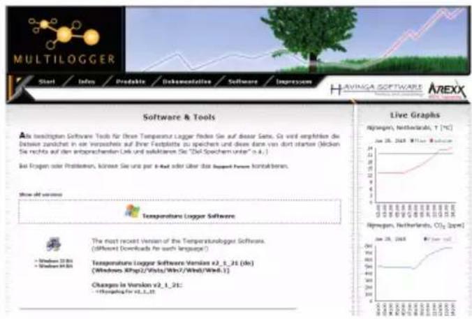
SOFTWARE
The Multilogger software (Templlogger software) has been designed for Windows (and also for subsequent Windows versions) and is available for 32 bits and 64 bits systems. The software has been equipped with 4 languages.
You can download the most recent software versions from:
http://www.arexx.com.
The software package for the logger application also includes the USB-driver, the messenger and a great number of extra tools.
The website also provides users with detailed information to the Multilogger series of products.
If you are unable to receive any sensor data:
CHECK
- if you have the latest Software and Fimware
- Please check the "active"-box for the sensor filter list and deactivate the sensor filter list altogether.
3. MESSENGER
The Multilocator software contains messenger functionality (Messenger was installed, together with the multilocator software, on your PC).
The BS-510 receives measurement data from sensors and when connected with a PC the messenger software checks each measurement to the rules defined. A rule can also be checked on a timer event. A rule is a condition and an action definition. The condition is evaluated against the measurement if the evaluation results 'true', the defined action is performed. The rules are stored in a file that is stored on the PC.
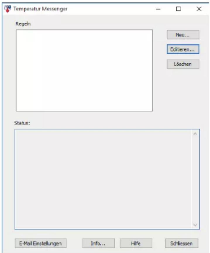
3.1 Messenger Rule Editor
Rules can be defined using the rule-editor, available from the Multilogger software package (see www.arexx.com)
The Rule-Editor is a tool for the creation of a rule-file that is used by the PC meseganger to control the Messenger software functions. The Messenger allows the start of one or more actions based on a incoming measurement value, if its associated condition is met. The available actions are the transmission of an e-mail and the transmission of a http request.
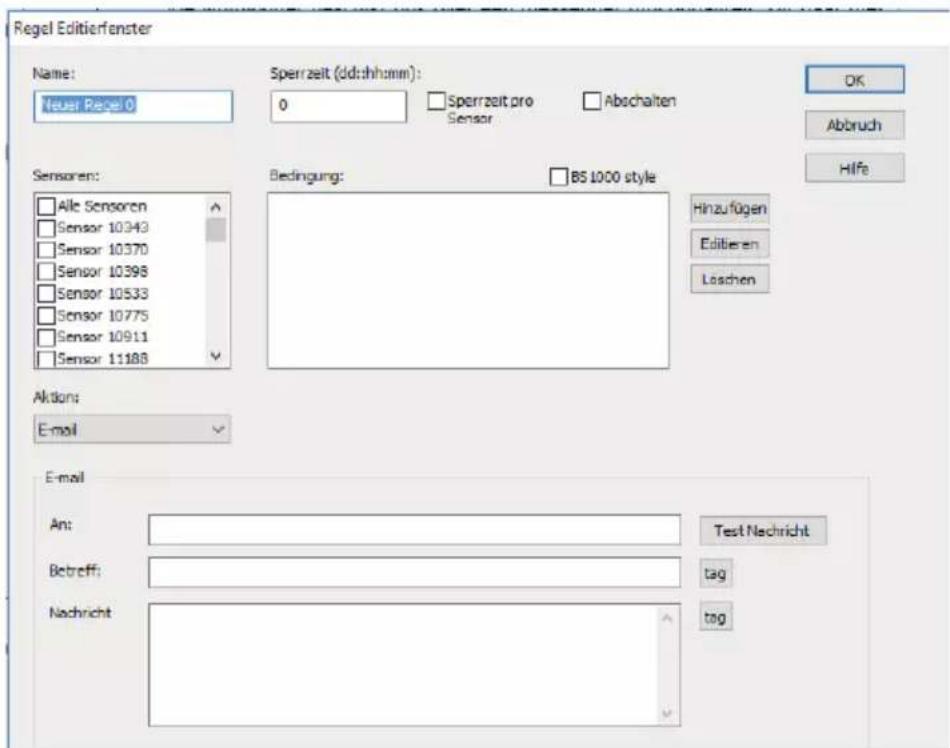
You can define multiple lines simultaneously. A rule always consists of a condition and its associated action. If the measurement satisfies the condition, the action will be executed. Evaluation of condition and action always takes place within the context of the incoming measurement.
Following parameters are required depending on the type of action:
For Email:
Name of the rule
Rule inhibition time
Condition for the rule
- Email address
- Email subject
- Email message
For HTTP request:
Name of thge rule
Rule inhibition time
Condition for the rule
- HTTP request type: GET, POST or PUT
- HTTP request url
- HTTP request message
The inhibition time specifies the number of seconds that the rule remains inactive after the rule action is performed.
Conditions
The condition is a logical expression that is evaluated within the context of the received measurement. The value of the measurement and its associated attributes will be evaluated as variables.
The following variables are available:
| Variable Description | |
| v Measurement | value |
| q sensor type 1 | = temperature (°C), 3 = RV% (%), 5 = CO2 (ppm) |
| i sensor | |
| r rssi value (dBm) | |
| h measurement | time in hour |
| m measurement | time in minutes |
| s measurement | time in seconds |
| Y measurement | time the year |
| |M measurement | time the month |
| D measurement | time the day |
| S measurement | time in seconds since 1-1-2000 UTC |
| c measurement | day of the week (0=sunday, 1=mondat, etc...) |
| a(len) running | average (len = length in seconds) |
| b(len) running | minimum (len = length in seconds) |
| e(len) running | maximum (len = length in seconds) |
| $p(dt) Previous value. If dt=0, then the previous measurement value is given, otherwise, the interpolated value at the moment of dt seconds back in time is given. | |
All time variables, except time (S) are UTC plus the time zone offset, is given in the Time server setting page. The time variables )S$ is in UTC.
The condition is structured like a logic expression. Following logical comparison operators can be used for the definition: (<, <=, >, > =, <>, == and != ), as well as the logical operators AND (&), OR (| |), and NOT (!). Also the arithmetic operations + , - , * , /, and % (modulo) can be used. Moreover the expression can be organised via the brackets " ", and " ".
Example
| Expression | Description |
| v<10 results in true when the me | measurement falls below the value 10. |
| v<10 && i=8297 results in true | when the measurement of sensor 8297 falls below the value 10. |
| (v<-10 || $v>10)&&c==0 results i | in true when the measurement falss -10 or is bigger than 10, and the weekday is sunday. |
The http message, email message and email subject text fields that can contain variables. The value of a variable will be replaced by text when the message text is set up.
The list of variables is:
| Variabile Description | |
| v measuement value | |
| q sensor type 1 = temperature (°C), 3 = RV% (%), 5=CO2 (ppm) | |
| i sensor id number | |
| r rssi value (dBm) | |
| h measurement time | in hour |
| m measurement time | in minutes |
| s measurement time | in seconds |
| Y measurement time | the year |
| M measurement time | the month |
| D measurement time | the day |
| S measurement time | in seconden since 1-1-2000 UTC |
| w missing time of last measurement which could not be redirected to http server. Used for temp logger synchronization | |
| t time string measerement time in hh:mm:ss format | |
| d date string. measerement time in short date format | |
| $p(dt) Previous value. | If dt=0, then the previous measurement value is given, otherwise, the interpolated value at the moment of dt seconds back in time is given. |
All time variables, except w and S, are in UTC plus the time zone offset given in the Time Server Setup page. The time variables wandS are in UTC.
The HTTP request message is url-encoded per default. This means that non-alphanumeric characters are converted into %hh-strings where „hh" represents a hexadecimal figure. The lines &&' and == ’ are an exception: these are converted into ‘&’, and ` == ’ respectively. The message for the HTTP request is transmitted via the request header POST, or else added to the URL of the GET request. In that case, the separating sign ‘?’ is added between the URL and the message.
Example message:
id == i && value == v
In this example, a web server is programmed to decode the indicated string in two parameters id' andvalue'. This method allows to supply up-to-date data from the BS1200 to a web page without a running a PC.
This mechanism is also used for the update of the temperature logger.
Flashed data
A special xml page is implemented to let other software retrieve data from the BSXXXX. The page data.xml outputs flashed data within a given period. The page is called with 4 parameters:
| Parameter name | Type Description | |
| A timestamp Start of period; number | of seconds since 1-1-2000 | |
| B timestamp End of period; number | of seconds since 1-1-2000 | |
| C integer Sensor id | ||
| D integer Sensor type; 1=temperature, 3=RH%, 5=CO2 | ||
Example:
http://log77.lan/data.xml?A=327682224&B=327685203&C=4096&D=1
This call would result in the following dataset:
<?xml version="1.0" encoding="utf-8"?>
<measurements>
    <value id="4096" type="1" t="327682224">25.1</value>
    <value id="4096" type="1" t="327682287">39.5</value>
    <value id="4096" type="1" t="327682335">33.7</value>
    <value id="4096" type="1" t="327682378">30.7</value>
    <more>327684165</more>
</measurements>
Die XML Data includes "measurements" elements as root elements. This element contains 0,1, or more value elements. Each value element constitutes a measurement and contains the following attributes:
-
type = Sensorotype; 1=Temperature, 3= RH, 5=CO2
-
t = Time; number of seconds from 1-1-2000
The value is shown as elementvalue.
The data transfer can take a long time this time can be shorter like above sample. this is done with the "MORE" element it shows which time the BSXXXX the last time called data from the Flash memory.
4. Transmission losses
Sometimes transmission losses may arise, indicated by missing temperature data in the sensor's curve display.
Data losses may be caused by:
- Problems inside the USB-receiver
- Problems in the temperature sensor module
- Problems in the signal transfer between temperature sensor module and USB-receiver
4.1. Problems inside the USB-receiver
The receiver does not register a single data signal, even if the sensor is located at a minimum distance to the receiver.
Potential problems:
- USB-cable between receiver and computer is missing or defect
- Improper installation of the USB-module
- Unknown software problem in the computer system
- Internal battery BS-510 is empty (replace the battery)
Suggested solutions:
- Check the display window in the temperature logger display for a "Synchronisation" window. The window is to display the value 'USB@x' continuously. If the display intermittently displays 'RF_USB-Communication failure', the Windows operating system failed to find the USB-module.
- Remove the USB-cable, wait about ten seconds and reconnect the cable.
- Deinstall the temperature logger application software and reinstall it again.
DC 5-7.5V / 500mA
USB
Led Green Receiving
Orange Flash data LED

Please check the clock battery (Type CR2032)
4.2. Problems in the temperature sensor module
The receiver receives signals from sensors, but fails to register signals from one sensor in particular.
Potential problems:
- Batteries are missing or are at a low charging level
- Reversed polarity of the sensor's batteries
- The sensor's location is outside of the receiver's reception range
- Damage to the sensor (by corroded battery contacts, moisture or battery leakage)
- Problems in the radio signal communication
Suggested solutions:
- Insert fully charged batteries in the sensor and repeat the communication test (please check the polarisation of the batteries before inserting!!)
- Check the battery contacts and remove all corrosion and moisture effects.
Technical details
Type: BS-510
Radio: ISM 433MHz, Multilogger RF-protocol.
USB: USB 2.0, Multilogger USB-protocol.
Supply: 5-7,5V DC / 500mA
RTC battery: CR2032 3V
Internal memory: 2MB data-flash, about 9 days for
10 sensors, 18 days for 5 sensors, etc.
Software: http://www.arexx.com
Extra information and possible updates can be found on www.arexx.com
Further questions can also be put on our forum, see www.arexx.com
4.3. Radio signal transfer problems
The receiver system is missing signals from one or more sensors, or only receiving a limited number of signals.
Potential problems:
- Walls or ceilings between sensor and receiver may contain metallic constructions.
- Sensors and/or receiver may be located on a metallic surface
- Sensor or receiver are situated in locations with high humidity
- Windows between sensor and receiver may contain several layers of glass or shielding materials or may be covered by humid moisture.
- Other 433MHz systems may be working within the 20m operating range
- Interference or jamming signals from radio or TV transmitters
- Electronic or electrical equipment (eg. computer equipment or magnetrons), operating within the 2-5m operating range
- Low power level of the sensor's batteries (see 1.2)
Suggested solutions:
- Modify the locations of the sensor and/or the receiver
- Remove the interfering equipment
4.4. Communication test
A simple test will check the communication channel between sensor and receiver:
- Remove the batteries from the sensor
- If an entry already exists: remove the sensor from the temperatur logger application (using the right mouse button)
- Locate the sensor at ca. 1 m distance to the receiver
- Insert the batteries in the sensor
- A correctly working system will add the according sensor entry to the sensor list within 5 seconds.
5. FIRMWARE UPDATES
Updating the Firmware
The Firmware of a BS-510 Sensors may be reprogrammed by performing the following steps:
- Download the most recent Firmware versions at www.arexx.com
- Unzip the ZIP-file.
- Start Flash by right-clicking (Right Mouse Button = run as an Admin).
- This will normally open a DOS-window.
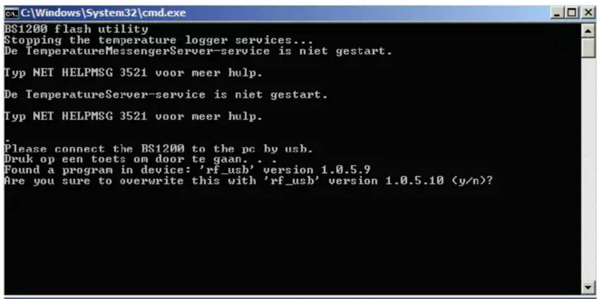
- Hit "enter" to proceed and Y.
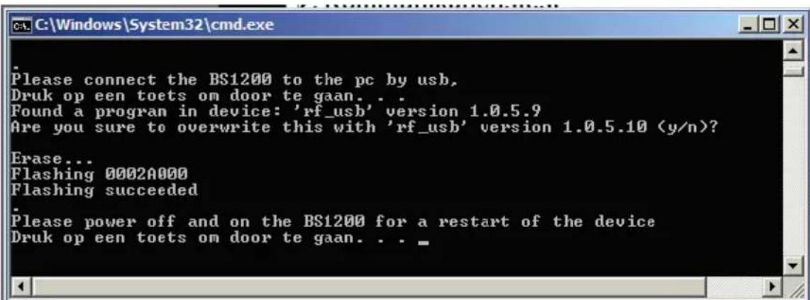
- The update has been successful as soon as Flash reports "success".
- Restart the BS-510.
APPENDIX TIPS
Checking the drivers
- Check (at: Start > Configuration window > Devices and Printers) the execution of RF-USB. Re-install the driver. Wait to connect the device until the installation process commands you to do so!
- Check the correct installation of the driver and the PC-connection. Check the entry 'USB@x' at the "Synchronisation" window of the Multilogger Software and the accompanying firmware version of the module. (Multilogger Software Menu - display section: Tools' section)
Checking the sensors
Insert batteries into the sensors. The sensors automatically will register themselves to the software. Check the "Sensorlist" window at the Multilogger Software (Multilogger Software Menu - display section: Tools' section). The sensors' list displays three columns: Sensor name, Date and Time stamp for the most recent measurement data and the referenced temperature value.
User manual for the Multilogger-Software
All user information for the Multilogger-Software may be found in the software's help-section.
Unknown sensors
You can remove the unknown sensors with the tool "Erase Data Flash Tool"
RESET BS-510
Remove power and inside battery for about 20 sconds.
WE ADVICE YOU TO REGULARLY UPDATE THE MULTILOGGER SOFTWARE VISIT: WWW.AREXX.COM
FAQ AREXX MULTILOGGER
What is a logger?
A logger receives sensor data for a given period of time by wireless channels. Our Multi logger periodically - every 45 seconds - registers e.g. temperature, humidity, voltages or other parameters and displays these values in a graphical representation. The considerable number of values allows the system therefore that a few values may have been missed.
What do we need to build an AREXX Multi logger system?
Three important items are necessary to build a Multi logger system;
- a receiver (BS-XXX, BS-XXXX or e.g. the TL9-ALU)
-
One or more sensors (AREXX TSN-, or the PRO-series)
-
or 1 or more BS-XX sensor,
- The AREXX logger software
The BS-500 / BS-1000 system does not work?
- start by checking if the Data Receive LED blinks occasionally
- did you correctly plug in, respectively connect the USB-cable?
- did you check and correctly connect the polarity (+ and -) of the external 5 Volt voltage?
- has the driver been installed correctly?
Check the entry 'USB@x' at the "Synchronisation" window of the Multilogger Software and the accompanying firmware version of the module. (Multilogger Software Menu - display section: Tools' section)
I have problems with the BS-XX, BS-XXX or BS-XXXX driver
Check the entry of RF-USB in the management for Devices and Printers (START > CONFIGURATION display > DEVICES & PRINTERS).
Repeat the driver's install procedure; Be careful to connect the device only after a request by the installation software!
The receiver is listed in the device management, but the sensor list does not contain any sensor. The Data Receive LED does not blink.
Three possible problems can be the result of this situation:
-
The sensors do not transmit any signal
-
check the batteries (for polarity and voltage)
-
The sensors have not been positioned inside the receiver's range
-
position the sensor(s) next to the receiver
-
The receiver does not work properly
-
exchange the receiver for a new one.
The receiver receives data (Data LED occasionally blinks) but the sensor list does not contain entries.
The filter in the sensor list may have been activated (start the Logger software > Menu list > arrow below > sensor filter list). This filter list must be empty. Otherwise the system will only receive the listed sensors in this list!
How do I check the sensor's operation?
Take care to place the sensors in the receiver's vicinity (at e.g. 3 meters or less). Check the battery's voltage, which should at least be 1.3 Volt for each individual cell. Insert the battery cells into the sensor and be careful to choose the correct polarity (+ and -)!
Within 5 seconds after inserting the last cell, the sensor will start transmitting, automatically blinking the green LED, followed by the listing of the sensor in the sensor list.
Is a wireless sensor interfering with other equipment?
The sensor will transmit periodically at a rate of 1 message/minute. The message is very short (milliseconds) at a low energy level. Therefore permanent interference cannot be caused by the sensors. These sensors cannot be compared to a wireless headset (which will permanently transmit signals) or mobile phones (which use high RF-energy levels).
The sensors display different values although they are located next to each other.
The sensors may all be working with a certain margin. One of the temperature sensors may deviate 0.5 degree upwards and the other sensor may deviate 0.5 degree downwards, which would sum up to a difference of 1 degree! Still both sensors may be working within their tolerance levels and specifications. Other causes for differences may be the local position, draught and the sunlight respectively shadow position of the sensors.
Are the sensors calibrated and how can we calibrate the system?
We use digital sensors, which are guaranteed to work within their factory specifications. Some customers (hospitals and pharmacies) order certified specialists to calibrate their AREXX sensors once a year at their installed equipment site.
Systematic deviations and tolerances may be compensated by an offset value in the software. See Logger Software (Sensor List > Left mouse click on sensor > Sensor properties > Offset).
What is the difference between IP-, TSN- and PRO sensors?
All sensor types are based on the same operation principles and you can use them all in one system at the same time. PRO sensors are equipped with a display, can operate with an external supply from a junction box and are splash proof. The IP sensor are waterproof.
Do the sensors operate inside a refrigerator or freezer?
Frequently our sensors are being used in temperature controlled boxes, refrigerators and freezers, which are located in professional kitchens, laboratories and pharmacies. Both for hygienic reasons and battery capacity we do not recommend to locate complete sensors inside refrigerators or freezers.
We recommend to use external sensors, which are located inside the low temperature area and position the electronic circuits and battery outside the low temperature area.
Do the sensors provide us with a battery level indicator?
Unfortunately the sensors do not provide us with a battery level indicator. There was a choice between a signal level indicator (RSSI) and a battery level indicator. In designing the system we identified the great variety of communication signal levels and did choose for the signal level indicator.
How long will an average battery last?
Good AAA lithium cells will allow the TSN -and PRO sensors to operate circa one year. The IP sensors with good AA lithium cells can operate about 2 years or more. In colder areas it is possible that this operation time is considerably shorter.
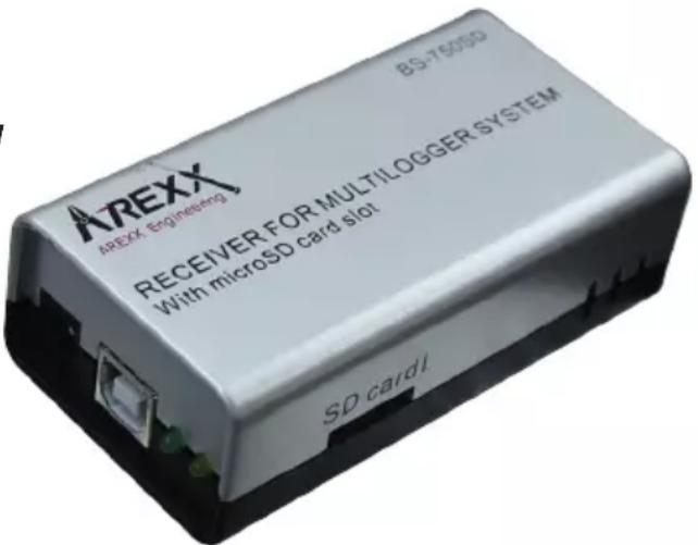
What is the difference between BS-500/TL-500, BS-510 and TL-510?
The difference can be found in the internal backup battery for the internal clock. All other functionality is 100% equal. The battery will operate the internal clock during a power failure and prevents an (automatic) adjustment to the PC's clock. Therefore the internal backup battery allows you to continually proceed with the logging process at power failures. There is also a new BS-750SD receiver also with internal clock battery and an SD card for long time storage.
How do we reset the BS-XXX or BS-XXXX?
Switch off the module and remove the internal backup battery for 20 seconds.
If the BS-510 or BS-1000 shortly operate in memory mode, the data storage does not contain any data, although the yellow LED is flashing?
That is correct. The (permanent) flash memory has been provided with a small temporary memory, which is not permanent. The temporary memory must be filled before the contents is transferred to the flash memory. If the module is switched off before the first data has been transferred to the flash memory, no data will be stored permanently at all.
After connecting the BS-510 or BS-1000 to the PC, the system does not transfer any data to the PC?
The logger software will transfer data as soon as the software has succeeded to connect the PC to the module. If the automatic connection is failing, please check the following points:
- The logger software has been installed and is working
- The connection to the base station is active: the logger receives new sensor data.
- The flash memory does contain data.
- The flash memory is working, try to empty the Flash with the tool in the logger software.
How to remove the memory's contents at the BS-510 or BS-1000 (the yellow LED is illuminated)
Visit the BS-XXXX 'maintenance' page at the menu section 'administrative pages'. In this section you will find a button to reset the flash memory. T his command also checks the functionality of the flash memory.
Use the tool "erase Data Flash Tool" in MENU--> TOOLS in the Logger Software
How can I check the functionality of the internal memory?
We advise to use the flash test at our website. You may also apply the test at the BS-1000's 'maintenance' page (see the previous FAQ).
For what purposes may I use the Messenger?
The messenger software enables you to send messages by email and/or http, in which the most recent sensor data are included.
Optionally you may program transmission for special conditions, e.g.: the temperature is below zero degrees. The http-messages may also be used to update a webserver with recent sensor data in real-time. The PC-version of the messenger allows you to execute a cmd shell script, whereas the BS-XXXX/TL-09 version is capable of triggering a buzzer.
For further information see: the Manual_BS1000_messenger.pdf
What are RULES?
The messenger software has been equipped with so-called rules to control the triggering of events by incoming sensor data. For a logger, a number of rules may be defined. A rule is a description containing a conditional statement and a definition for action. If the given conditions have been fulfilled, the defined action (for example sending an email) the will be triggered.
How can I to use rules?
Rules may be defined in the logger software, or by rule-editor, for the BS-XXXX/TL-09. The rule editor defines a rule file, containing 1 or several rules. You may upload the rule file to the base station. The BS-XXX however will only work with a pc software.
What is an example for a rule?
(v< 0 ||v>9) && $i==11867
How to transfer a rule into the BS-XXX or BS-XXXX receiver?
The BS-XXX will only work with the pc software and does not allow the uploading of rule files. In this case rules will be defined within the messenger software. The BS-XXXXTL-09 may be working independently from the pc software. These modules allow you to upload a rule file, which may be organized in several ways:
BS-XXXX via the network:
- using the embedded webserver: visit the "rules"-page in the section 'administrative pages'.
- using the rule editor: menu Extra->'Upload current file to bs1000'.
Via USB:
- using the ConfigFileUpload tool: via USB you may upload rule files and other configuration files to the station.
The BS-XXXX cannot be accessed by the network?
Check the network connection; has the network connector correctly been plugged? Check the network by connecting a laptop to the plug.
Connect the USB and a network cable. Use the Networkconfig-tool in the tool menu at the logger software. With the help of this tool you will find the current IP-address for the BS-XXXX.
Check the DHCP server if this is being used.
Use the internet browser to contact the BS-XXXX. Apply the IP address you did find with the help of the Networkconfig-tool.
Check whether the BS-XXXX works by USB port.
Check the blinking of the LED next to the network connector at the BS-XXXX. Flash the most recent firmware in de BS-XXXX (download via www.arexx.com/templogger)
Check the firewall and virusscanner.
Ask your network administrator for help.
Why am I unable to login to the BS-1000 as an admin?
Sometimes you will have to wait for a few minutes before you are allowed to login again. T
he BS-XXXX will hold an admin session for 2 minutes. However the system has been programmed to refuse more than one admin session simultaneously. We advise you to use the logout link for leaving the administrative pages. In this case you may login immediately without any delay.
Check the IP-address: has the address been modified by the DHCP-server.
Can we use the sensor data for our own software?
Yes, check the documentation for data access at START > ALL PROGRAMS > Temperature Logger > Help > Server Interface Help. The BS-XXXX will also allow the use of messenger functionality. Apart from these options, you may also use the cdata.xml page to output the most recent sensor data in xml format.
Can we display the BS-XXXX sensor data in the Web?
You may also use www.multilogger.nl as a structured logger for a number of sensors.
And for the specialists: set up your own webserver....
Is it possible to receive my BS-XXXX data at my laptop as well?
Yes, there are several ways to do so:
(1) directly via USB, or
(2) alternatively using the synchronisation functionality (see the next question),
(3) by applying a webserver.
Is it possible to display this information at several PC's or laptops?
Yes, by using the sync file configuration tool. The synchronisation functionality of the logger software allows you to split up data for several PC's or join data from different sources. The system allows the usage and cooperation of several BS-XXXX. The http-protocol is used for communication. There is also a Wizard in the "SyncFileConfig" TOOL.
How do I set up the system to display data at several laptops/PC's?
Use the Sync file config tool in the tool menu of the logger software. The most simple strategy is to link a BS-XXXX to the PC (by a network link) and to expand the system from this core system. Connecting the BS-XXXX is simplified by using the BS-XXXX wizard, in which the logger software is configured - to be followed by an upload of the rule file to the BS-XXXX.
The sync file config tool generates an xml-file, describing the data-sources for the logger-software and a description of possible addressees for the sensor data, to which the logger-software is to send the data.
For further information see the Synchronization_Configuration_Tool.pdf
How do I receive my PC BS-500 data at my laptop?
To do so please apply the synchronisation functionality of the logger software. Open the sync file config tool. At the PC name enter a network's name (in this case the laptop's name) as the target to which the PC-logger is going to send data. At the laptop we follow the same procedure, but this time you will have to specify the data source (in this case the PC).
For further information see the Synchronization_Configuration_Tool.pdf
How to transfer the old temp logger data to another PC?
Use the backup functionality (file-> export backup), which will generate a zip-file with all logger data.
Then install the logger software at your new PC and apply the import backup function to import the zip file created at the first PC.
I did modify several setup parameters in the software (e.g. names and colours), which suddenly have disappeared.
In a standard situation, these data has been stored in the document directory (TempLogSetting.xml). Inspect the directory for the setup data (Logger Menu > save File setup-data) and check for the file "TempLogSetting.xml". Save the setup parameters in a directory for which you always have sufficient rights.
Can we use sensor data to control external devices?
The SAM-04 LAN network I/O relais box enables you to switch off and on devices. The SAM directly can communicate with the BS-XXXX. This option allows you to directly use the logger's data to control external devices. The complete system, BS-XXXX and the SAM, can also be surveyed and controlled from a remote website.
Is there an APP for the Multilogger?
Yes there is an Android app in the Google playstore
A. USB connector
B. DC connector
Leveromvang BS-510
| Variable Desc | iption |
| v Measured value | value |
| q Sensor type | 1 = Temperature (°C), 3 = RH% (%, 5=CO2 (ppm) |
| i Identification | number of the sensor |
| r rssi-value (dBm) | |
| h Indication of | the hours in the time indication of the measurement |
| m Indication of | of the minutes in the time indication of the measurement |
| s Indication of | the seconds in the time indication of the measurement |
| Y Indication of | the year in the time indication of the measurement |
| |M Indication of | the month in the time indication of the measurement |
| D Indication of | the day in the time indication of the measurement |
| S Measurement | time in seconds since 1-1-2000 UTC |
| c Day of the week | week at the time of measurement (0=Sunday, 1=Monday...) |
| a(len) Current | running average value (len = Length in seconds) |
| b(len) Current | running minimum value (len = Length in seconds) |
| e(len) Current | running maximum (len = Length in seconds) |
| $p(dt) Previous | value. If dt=0, then the previous measurement value is given, otherwise, the interpolated value at the moment of dt seconds back in time is given. |
| Expression Description | |
| v<10 | is true as soon as the measurement goes below the value 10 . |
| v<10 && i=8297 | is true as soon as the measurement for sensor 8297 goes below the value 10 . |
| (v<-10 || v>10)&&c==0 | is true as soon as the measurement goes below the value -10 or above10 and the day of the week is a Sunday. |
| Variable | Description |
| v Measured value | |
| q Sensor type 1 = Temperature (°C), 3 = RV% (%), 5 = CO2 (ppm) | |
| i Identification number of the sensor | |
| r rssi-value (signal level value in dBm) | |
| h Indication of the hours in the time indication of the measurement | |
| m Indication of the minutes in the time indication of the measurement | |
| s Indication of the seconds in the time indication of the measurement | |
| Y Indication of the year in the time indication of the measurement | |
| |M Indication of the month in the time indication of the measurement | |
| D Indication of the day in the time indication of the measurement | |
| S Measurement time in seconds since 1-1-2000 UTC | |
| w Missing; Time when the latest measured value has not been transmitted to the http server. Is required for the update of the temp-logger. | |
| t time string; Time of measurement in the format: hh:mm:ss | |
| d date string; Date of the measurement in the short date format | |
| p(dt) Previous value. If dt=0, then the previous measurement value is given, otherwise, the interpolated value at the moment of dt seconds back in time is given. | |
| $XXml data; generates an xml list of the most recent measurements. To be used in conjunction with the timed rule type. The xml format is the same as the output from the data.xml page (see below). | |
BS-1000 via network:
- via de embedded webserver: de rules网首页 van de 'administrative pages'.