IP-52 - Measuring equipment AREXX - Free user manual and instructions
Find the device manual for free IP-52 AREXX in PDF.
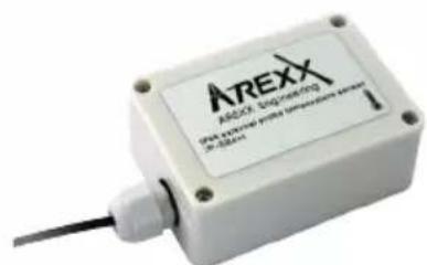
| Product type | Wireless indoor temperature sensor |
| Brand | AREXX |
| Model | IP-52 |
| Category | Measurement equipment |
| Temperature measurement range | -55°C to +125°C (depending on model, typically ±1°C from +25°C to +65°C) |
| Accuracy | ±1°C (max.) from +25°C to +65°C; ±2°C from -40°C to +85°C |
| Transmission range | 90 m (free field: 180 m) |
| Radio frequency | 433 MHz |
| Power supply | 2 AA batteries (not included) |
| Dimensions (L x W x H) | 60 x 33 x 120 mm |
| Weight (with batteries) | Approximately 150 g |
| Main functions | Wireless temperature measurement and transmission, continuous recording on USB receiver, graphical display via Multilogger software, threshold alarms (via software) |
| Compatibility | AREXX USB, LAN, WiFi, GPRS receivers (base station) |
| Protection rating | IP66 (water-resistant, depending on version) |
| Maintenance and cleaning | Clean with a soft, dry cloth. Do not use abrasive products. Avoid excessive moisture. |
| Safety | Do not expose to temperatures outside the specified range. Use recommended battery type. Respect battery polarity. |
| Spare parts and repairability | Replacement batteries available. For external probes, contact customer service. No user-serviceable parts. |
| General information | Manual downloadable at notice-facile.com. Software and updates at www.arexx.com. |
Frequently Asked Questions - IP-52 AREXX
User questions about IP-52 AREXX
0 question about this device. Answer the ones you know or ask your own.
Ask a new question about this device
Download the instructions for your Measuring equipment in PDF format for free! Find your manual IP-52 - AREXX and take your electronic device back in hand. On this page are published all the documents necessary for the use of your device. IP-52 by AREXX.
USER MANUAL IP-52 AREXX
- General Multilogger Information 11
- Instructions & specifications IP66 sensors 13
- Communication test
- Transmission problems 15
14
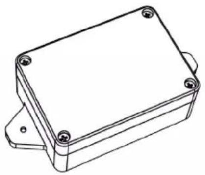
natural_image
Technical line drawing of a rectangular electronic enclosure with mounting holes (no text or symbols)IP-HA90
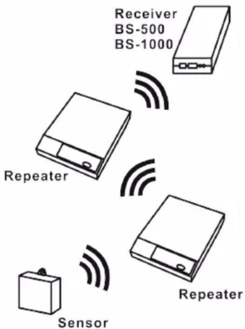
Abb. 11. Repeater Konfiguration
1. MULTILOGGER INFORMATION
Starting up
- First please read this complete manual before you continue.
- More manuals can be found on the CD and in our Multilogger Software HELP FUNCTION.
- Install the software, please refer to the manual on the CD-ROM! Always check on www.arexx.com if you have the latest software version at hand.
- Connect the USB receiver to the computer.
- Start the program.
- Insert batteries in the sensors.
- Consult the help function of the software if you have further questions.
Important information about the MULTILOGGER Logger
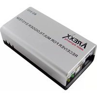
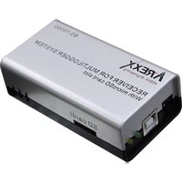
- The receiver which is connected to the computer receives the signals coming from the sensors.
- The computer can also collect the sensor data from a LAN Network.
- The temperature sensors transmit their temperature data to the receiver.
- Several temperature sensors can be connected to the system at the same time.
- Separate sensors for the Multilogger are available at your dealer.
- We have connected 60 sensors to one single USB receiver without any problems.
- The software graphically shows the temperature measurements of a longer period of time.
- Extra: Attractive screensaver software showing all sensors.
- The range of the sensors can vary as a result of environmental influences.
Depending on the material properties of the surrounding areas, sensors located inside refrigerator systems may not be able to communicate with the receiver.
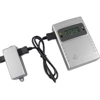
The Multilogger System consists of a logger loftware application, a USB-, LAN-, WIFI- or GPRS receiver module and one or more sensors TSN-XX, PRO-XX, IP-XX, each including a transmitter system.
A USB- or LAN cable connects the receiver to the computersystem or to the LAN network. The Logger application can synchronize the sensor data from several receivers.
For the multilogger system many different sensors are already available. The sensors can measure temperature -200 to +400°C (PT-100), humidity, Voltage and CO2
The multilogger application at the computer displays all sensor data, which have been transferred by temperature sensors to the receiver.
Temperature sensors continuously register temperature and report new values to the USB-, LAN-, WIFI- or GPRS receiver at intervals of ca. 45 seconds.
Each sensor in the sensorlist reports the date and time stamp for the most recent measurement data set. The right side window displays a continuous curve for the registered temperature for the selected sensor.
Sensors and receiver use a wireless communication system, working at 433MHz. This frequency is freely available for communication at transmitting powers under 10 milliwatts.
Depending on surrounding building constructions, the allowed 10mW power level allows a transmission range of 20-40 meters inside buildings, the open field range is much higher.
Temperature sensors may be located inside or outside buildings, at any place where a registered overview of temperature curves is desired.
Unreliable signal levels may be improved substantially by slightly modifying the sensor's position or the receiver's location.
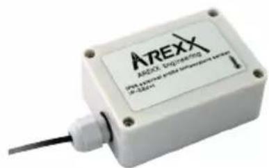
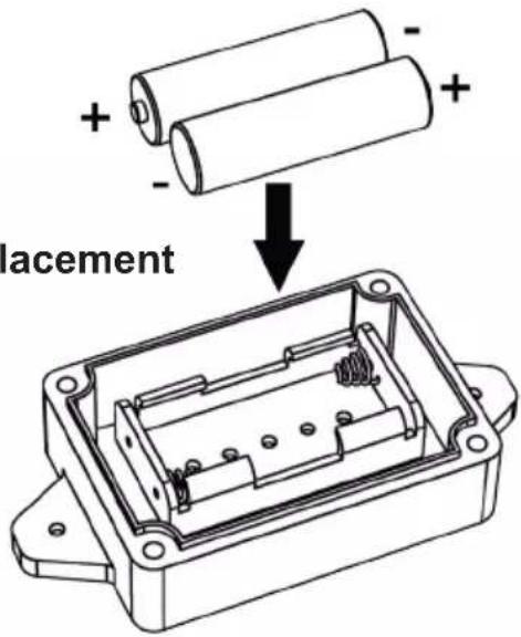
2. MANUAL & SPECIFICATIONS IP66 SENSORS
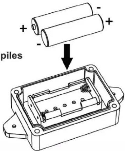
Insert the batteries as shown on the picture.
natural_image
Technical line drawing of a rectangular electronic enclosure with mounting holes (no text or symbols)Fig. 1. Battery placement
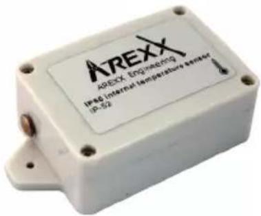
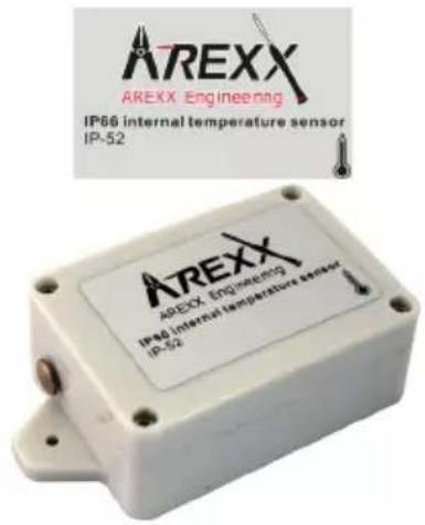
IP-52
IP66 Waterproof temperature sensor:
Transmitting range 90 m. (Freifeld: 180 m.)
Measurement range and accuracy:
- ± 1^ (max.) from +25^ bis +65^
- ±2°C (max.) from -40°C bis +85°C
- ±3°C (max.) from -55°C bis +125°C
Powered by 2 Pcs. AA-Batteries
Size (WxDxH) 60x33x100 mm

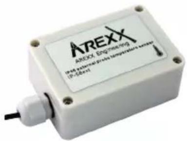
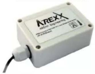
IP-58ext
IP66 Waterproof temperature sensor with external probe:
Transmitting range 90 m. (Freifeld: 180 m.)
Measurement range and accuracy:
- ± 1^ C (max.) from +25^ C bis +65^ C
- ± 2^ (max.) from -40°C bis +85°C
- ± 3^ (max.) from -55^ bis +125^
Wirelength ± 750 mm
Powered by 2 Pcs. AA-Batteries
Size (WxDxH) 60x33x100 mm

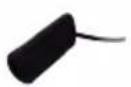
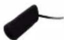
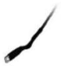
External probe

![AREXX Enginebox Test external intake temperature sensor [0-5min]](/content/2026/04/659928/images/964035534eeb98e8332c94dd04d4faad11ef5429f43f0be6b866c254014b8d8e.jpg)
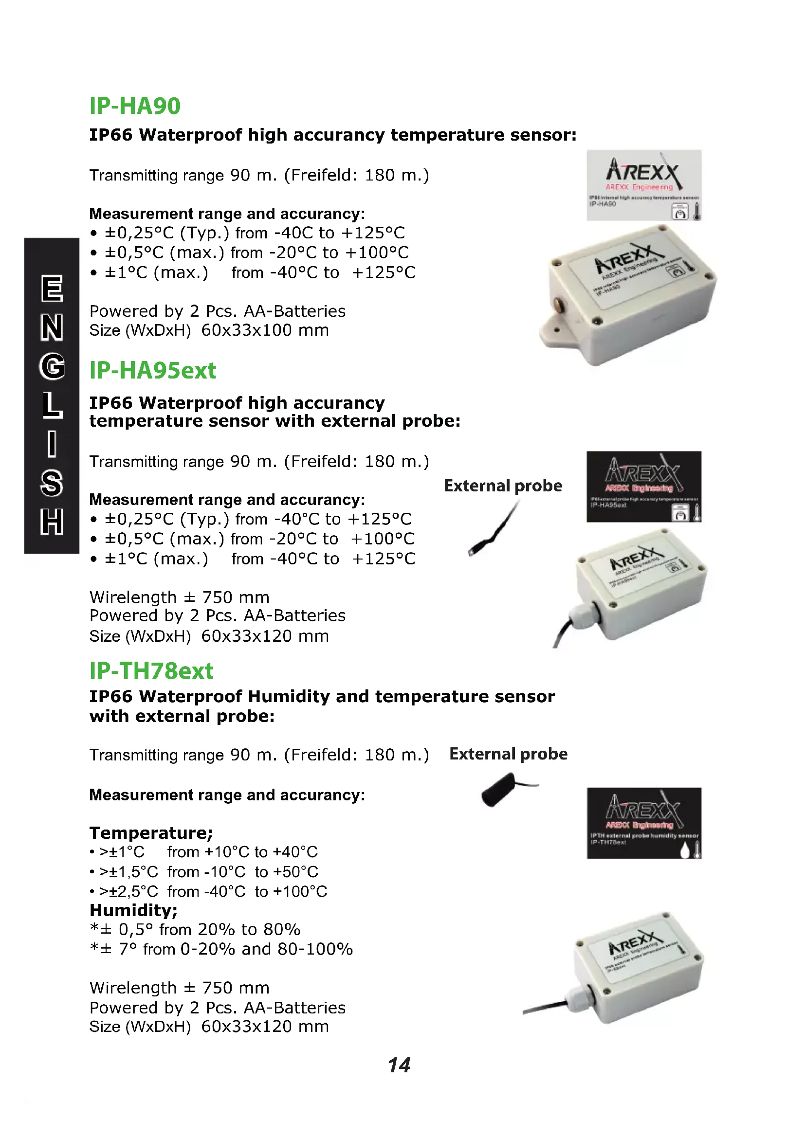
IP-HA90
IP66 Waterproof high accuracy temperature sensor:
Transmitting range 90 m. (Freifeld: 180 m.)
Measurement range and accuracy:
- ± 0,25^ (Typ.) from -40C to +125°C
- ± 0,5^ (max.) from -20^ to +100^
- ± 1^ (max.) from -40°C to +125°C
Powered by 2 Pcs. AA-Batteries
Size (WxDxH) 60x33x100 mm
IP-HA95ext
IP66 Waterproof high accuracy temperature sensor with external probe:
Transmitting range 90 m. (Freifeld: 180 m.)
Measurement range and accuracy:
- ± 0,25^ (Typ.) from -40^ to +125^
- ±0,5°C (max.) from -20°C to +100°C
- ± 1^ (max.) from -40^ to +125^
Wirelength ± 750 mm
Powered by 2 Pcs. AA-Batteries
Size (WxDxH) 60x33x120 mm
External probe


IP-TH78ext
IP66 Waterproof Humidity and temperature sensor with external probe:
Transmitting range 90 m. (Freifeld: 180 m.)
Measurement range and accuracy:
Temperature;
• >±1°C from +10°C to +40°C
• >±1,5°C from -10°C to +50°C
- >±2,5°C from -40°C to +100°C
Humidity;
*± 0,5° from 20% to 80%
*± 7° from 0-20% and 80-100%
Wirelength ± 750 mm
Powered by 2 Pcs. AA-Batteries
Size (WxDxH) 60x33x120 mm
External probe

3. Transmission losses
Sometimes transmission losses may arise, indicated by missing temperature data in the sensor's curve display.
Data losses may be caused by:
- Problems inside the USB, LAN, WIFI, GPRS-receiver
- Problems in the temperature sensor module
- Problems in the signal transfer between temperature sensor module and USB, LAN, WIFI, GPRS-receiver
3.1. Problems inside the USB, LAN, WIFI, GPRS-receiver
The receiver does not register a single data signal, even if the sensor is located at a minimum distance to the receiver.
Potential problems:
- USB-cable between receiver and computer is missing or defect.
- Improper installation of the USB, LAN, WIFI, GPRS-module.
- Unknown software problem in the computer system.
Suggested solutions:
- Check the display window in the temperature logger display for a field in the lower left area. The field is to display the value ‘ready’ continuously. If the display intermittently displays
'RF_USB-Communication failure', the Windows operating system failed to find the USB-module.
- Remove the USB-cable, wait about ten seconds and reconnect the cable.
- Deinstall the temperature logger application software and reinstall it again.
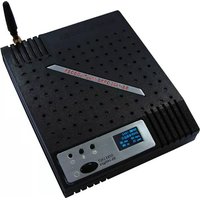
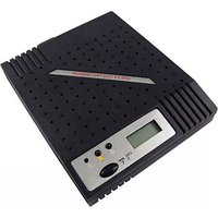
Configuration example with several repeater stations for a longer range
Fig. 11. Repeater configuration
3.2. Problems in the temperature sensor module
The receiver receives signals from sensors, but fails to register signals from one sensor in particular.
Potential problems:
- Batteries are missing or are at a low charging level
- Reversed polarity of the sensor's batteries
- The sensor's location is outside of the receiver's reception range
- Damage to the sensor (by corroded battery contacts, moisture or battery leakage)
- Problems in the radio signal communication
Suggested solutions:
- Insert fully charged batteries in the sensor and repeat the communication test (please check the polarisation of the batteries before inserting!!)
- Check the battery contacts and remove all corrosion and moisture effects.
3.3. Radio signal transfer problems
The receiver system is missing signals from one or more sensors, or only receiving a limited number of signals.
Potential problems:
- Walls or ceilings between sensor and receiver may contain metallic constructions.
- Sensors and/or receiver may be located on a metallic surface.
- Sensor or receiver are situated in locations with high humidity.
- Windows between sensor and receiver may contain several layers of glass or shielding materials or may be covered by humid moisture.
- Other 433MHz systems may be working within the 20m operating range.
- Interference or jamming signals from radio or TV transmitters.
- Electronic or electrical equipment (eg. computer equipment or microwave ovens), operating within the 2-5m operating range.
- Low power level of the sensor's batteries (see 2)
Suggested solutions:
- Modify the locations of the sensor and/or the receiver.
- Remove the interfering equipment.
4. Communication test
A simple test will check the communication channel between sensor and receiver:
- Remove the batteries from the sensor.
- If an entry already exists: remove the sensor from the temperatur logger application (using the right mouse button).
- Locate the sensor at ca. 1 m distance to the receiver.
- Put the batteries back into the sensor.
- A correctly working system will add the according sensor entry to the sensor list within 5 seconds.
Extra information and possible updates can be found on www.arexx.com (on the forum or through the Temp Logger menu).
Further questions can also be put on our forum,
see www.arexx.com
1. ENREGISTREUR DE MULTILOGGER
Mise en service
natural_image
Technical line drawing of a rectangular electronic enclosure with mounting holes (no text or symbols)Fig. 1. Insertion des piles
IP-52
Dimensions: (LxPxH) 60x33x100 mm
IP-58ext
IP-HA90
Dimensions: (LxPxH) 60x33x100 mm
IP-HA90ext
Solutions possibles:
Solutions possibles:
Solutions possibles:
1. MULTILOGGER INFORMATIE
Opstarten
natural_image
Technical line drawing of a rectangular electronic enclosure with mounting holes (no text or symbols)Abmessung (BxDxH) 60x33x120 mm
Externe voeler


IP-HA90
Afmeting (BxDxH) 60x33x120 mm
Externe voeler

Externe voeler