
ValveKing 20 MH - Audio Amplifier PEAVEY - Free user manual and instructions
Find the device manual for free ValveKing 20 MH PEAVEY in PDF.

| Product Type | Tube Audio Amplifier |
| Brand | Peavey |
| Model | ValveKing 20 MH |
| Dimensions (HxWxD) | 184 x 356 x 197 mm |
| Weight | 7 kg |
| Rated Power | 20 W RMS into 8 or 16 Ω |
| Power Consumption | 90 W, 50/60 Hz, 120 VAC |
| Power Tubes | 2 x EL84 |
| Preamp Tubes | 3 x 12AX7/ECC83 |
| Guitar Inputs | 1 high impedance input (1 MΩ) |
| Channels | 2 channels (Clean and Lead) footswitchable |
| Equalization | Passive Bass, Middle, Treble (common to both channels) |
| Reverb | Yes, adjustable and footswitchable |
| Effects Loop | Yes, with send and return, footswitchable |
| Vari-Class Control | Yes, patented, from Class A to A/B |
| Power Attenuator | 3 positions: 100%, 25%, 5% (20 W, 5 W, 1 W) |
| Headphone Output | Yes, stereo mini-jack |
| MSDI Output (XLR) | Yes, with microphone simulator, ground lift switch |
| USB Output | Yes, for direct recording to computer |
| Speaker Outputs | 1 output, selectable impedance 16 Ω or 8 Ω |
| Speaker Disable Switch | Yes, for silent use with headphones or recording |
| Footswitch Jacks | 2 jacks for dual footswitch (channel select, boost, reverb, loop) |
| Tube Status Indicator (TSI) | Green LED (normal) / Red LED (fault or standby) |
| Power Supply | 120 VAC, internal voltage selector |
Frequently Asked Questions - ValveKing 20 MH PEAVEY
User questions about ValveKing 20 MH PEAVEY
0 question about this device. Answer the ones you know or ask your own.
Ask a new question about this device
Download the instructions for your Audio Amplifier in PDF format for free! Find your manual ValveKing 20 MH - PEAVEY and take your electronic device back in hand. On this page are published all the documents necessary for the use of your device. ValveKing 20 MH by PEAVEY.
USER MANUAL ValveKing 20 MH PEAVEY
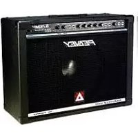
natural_image
Three black audio amplifiers (TV1, TV2, Venet) with visible brand logos and control knobs, displayed against a plain background.
Intended to alert the user to the presence of uninsulated “dangerous voltage” within the product’s enclosure that may be of sufficient magnitude to constitute a risk of electric shock to persons.
Intended to alert the user of the presence of important operating and maintenance (servicing) instructions in the literature accompanying the product.
CAUTION: Risk of electrical shock — DO NOT OPEN!
CAUTION: To reduce the risk of electric shock, do not remove cover. No user serviceable parts inside. Refer servicing to qualified service personnel.
WARNING: To prevent electrical shock or fire hazard, this apparatus should not be exposed to rain or moisture, and objects filled with liquids, such as vases, should not be placed on this apparatus. Before using this apparatus, read the operating guide for further warnings.

Protective earthing terminal. The apparatus should be connected to a mains socket outlet with a protective earthing connection.

IMPORTANT SAFETY INSTRUCTIONS
WARNING: When using electrical products, basic cautions should always be followed, including the following:
-
Read these instructions.
-
Keep these instructions.
-
Heed all warnings.
-
Follow all instructions.
-
Do not use this apparatus near water.
-
Clean only with a dry cloth.
-
Do not block any of the ventilation openings. Install in accordance with manufacturer's instructions.
-
Do not install near any heat sources such as radiators, heat registers, stoves or other apparatus (including amplifiers) that produce heat.
-
Do not defeat the safety purpose of the polarized or grounding-type plug. A polarized plug has two blades with one wider than the other. A grounding type plug has two blades and a third grounding plug. The wide blade or third prong is provided for your safety. If the provided plug does not fit into your outlet, consult an electrician for replacement of the obsolete outlet.
-
Protect the power cord from being walked on or pinched, particularly at plugs, convenience receptacles, and the point they exit from the apparatus.
-
Only use attachments/accessories provided by the manufacturer.
-
Use only with a cart, stand, tripod, bracket, or table specified by the manufacturer, or sold with the apparatus. When a cart is used, use caution when moving the cart/apparatus combination to avoid injury from tip-over.
-
Unplug this apparatus during lightning storms or when unused for long periods of time.
-
Refer all servicing to qualified service personnel. Servicing is required when the apparatus has been damaged in any way, such as power-supply cord or plug is damaged, liquid has been spilled or objects have fallen into the apparatus, the apparatus has been exposed to rain or moisture, does not operate normally, or has been dropped.
-
Never break off the ground pin. Write for our free booklet "Shock Hazard and Grounding." Connect only to a power supply of the type marked on the unit adjacent to the power supply cord.
-
If this product is to be mounted in an equipment rack, rear support should be provided.
-
Note for UK only: If the colors of the wires in the mains lead of this unit do not correspond with the terminals in your plug, proceed as follows: a) The wire that is colored green and yellow must be connected to the terminal that is marked by the letter E, the earth symbol, colored green or colored green and yellow. b) The wire that is colored blue must be connected to the terminal that is marked with the letter N or the color black. c) The wire that is colored brown must be connected to the terminal that is marked with the letter L or the color red.
-
This electrical apparatus should not be exposed to dripping or splashing and care should be taken not to place objects containing liquids, such as vases, upon the apparatus.
-
The on/off switch in this unit does not break both sides of the primary mains. Hazardous energy can be present inside the chassis when the on/off switch is in the off position. The mains plug or appliance coupler is used as the disconnect device, the disconnect device shall remain readily operable.
-
Exposure to extremely high noise levels may cause a permanent hearing loss. Individuals vary considerably in susceptibility to noise-induced hearing loss, but nearly everyone will lose some hearing if exposed to sufficiently intense noise for a sufficient time. The U.S. Government's Occupational Safety and Health Administration (OSHA) has specified the following permissible noise level exposures:
Duration Per Day In Hours Sound Level dBA, Slow Response
| 8 90 | |
| 6 92 | |
| 4 95 | |
| 3 97 | |
| 2 100 | |
| 1 1/2 102 | |
| 1 105 | |
| 1/2 | 110 |
| 1/4 or less | |
According to OSHA, any exposure in excess of the above permissible limits could result in some hearing loss. Earplugs or protectors to the ear canals or over the ears must be worn when operating this amplification system in order to prevent a permanent hearing loss, if exposure is in excess of the limits as set forth above. To ensure against potentially dangerous exposure to high sound pressure levels, it is recommended that all persons exposed to equipment capable of producing high sound pressure levels such as this amplification system be protected by hearing protectors while this unit is in operation.
a) The wire that is colored green and yellow must be connected to the terminal that is marked by the letter E, the earth symbol, colored green or colored green and yellow.
b) The wire that is colored blue must be connected to the terminal that is marked with the letter N or the color black.
c) The wire that is colored brown must be connected to the terminal that is marked with the letter L or the color red.
Logo referenced in Directive 2002/96/EC Annex IV(OJ(L)37/38,13.02.03 and defined in EN 50419: 2005
The bar is the symbol for marking of new waste and is applied only to equipment manufactured after 13 August 2005
Correct Disposal of this product. This marking indicates that this product should not be disposed with other house hold wastes throughout the EU. To prevent possible harm to the environment or human health from uncontrolled waste disposal, recycle it responsibly to promote the sustainable reuse of material resources. To return your used device, please use the return and collection systems, or contact the retailer where the product was purchased. They can take this product for environmental safe recycling.

FCC Compliancy Statement
This device complies with Part 15 of the FCC rules. Operation is subject to the following two conditions: (1) this device may not cause harmful interference, and (2) this device must accept any interference received, that may cause undesired operation.
Warning: Changes or modifications to the equipment not approved by Peavey Electronics Corp. can void the user's authority to use the equipment.
Note - This equipment has been tested and found to comply with the limits for a Class B digital device, pursuant to Part 15 of the FCC Rules. These limits are designed to provide reasonable protection against harmful interference in a residential installation. This equipment generates, uses and can radiate radio frequency energy and, if not installed and used in accordance with the instructions, may cause harmful interference to radio communications. However, there is no guarantee that interference will not occur in a particular installation. If this equipment does cause harmful interference to radio or television reception, which can be determined by turning the equipment off and on, the user is encouraged to try and correct the interference by one or more of the following measures.
- Reorient or relocate the receiving antenna.
- Increase the separation between the equipment and receiver.
- Connect the equipment into an outlet on a circuit different from that to which the receiver is connected.
- Consult the dealer or an experienced radio/TV technician for help.
ValveKing® 20MH & ValveKing® 100 Head
In order for the above two models to meet FCC/ICES requirements, a Steward 28A0592-0A2 ferrite core (or equivalent) must be placed on the USB cable where it exists/connects to the amplifier.
CAN ICES-3(B)/NMB/3(B)

Peavey Electronics Corporation • 5022 Hartley Peavey Drive • Meridian, MS • 39305
(601) 483-5365 • FAX (601) 486-1278 • www.peavey.com
Features and specifications are subject to change without notice.
© 2013 EX000190
ENGLISH
ValveKing® Series 100/50/20/20MH
Tube Amplifiers
Congratulations on the purchase of your new ValveKing® tube amplifier from Peavey. The latest ValveKing® series offers even more tube “Bang For Your Buck” than any other amp on the market.
The patented Vari-Class™ control allows for total control over the power amp dynamics and level by allowing for a “Class A” simulation or full-power “Class A/B operation”... or anything in between!
Two channels bring optimum flexibility in a small package. The Clean channel includes a Bright switch and separate three-band passive EQ (except for 20MH), allowing the Lead tone to be even more fine-tuned. The Lead channel also includes a footswitchable Boost feature. Depending on the specific model, this Boost may be selected for Gain and/or Volume via the front panel switches and footswitch. This capability gives you the equivalent of a three channel amp for the price of two.
Both channels share lush reverb and an effects loop, again both footswitchable.
Also the 20 and 50 combos both include a Damping control, while the 100 head offers Resonance and Presence controls for even more flexibility.
Other features on the rear panel include: Microphone Simulated Direct Interface (MSDI ^™ ) with balanced XLR output as well as USB out, external speaker outputs and impedance switch, speaker defeat switch and 3 position power attenuator switch.
Before you begin playing through your amplifier, it is very important to ensure that the product has the proper AC line voltage supplied. This is shown on the voltage selector switch near the IEC inlet on the rear panel of the unit.
Each product feature is numbered. Refer to the front panel diagram in this manual to locate the particular feature next to its number.
Please read this guide carefully to ensure your personal safety as well as the safety of your amplifier, not to mention being able to get the best out of it by fully understanding the features.
FEATURES:
- 6L6GC (100 and 50 models) or EL84 (20 and 20MH) power tubes and 12AX7/ECC83 preamp tubes
- 100 and 50 models can also accept EL34 power tubes if re-biased
• Patented Vari-Class™ control - Two footswitchable channels with independent, three-band EQ (except for 20MH)
- Footswitchable Gain/Volume Boost
- Depending on model, global Resonance, Presence, Damping and Reverb controls
- Buffered Effects Loop
• Paralleled Speaker Jacks (except for 20MH) - Impedance switch
- MSDI™ Output with XLR and ground lift switch
- USB Output
- Speaker defeat switch
• Headphone output (only on 20MH) - Attenuator switch for 100% , 25% or 5% of rated power

VENTILATION: For proper ventilation, allow 24" clearance from nearest combustible surface.
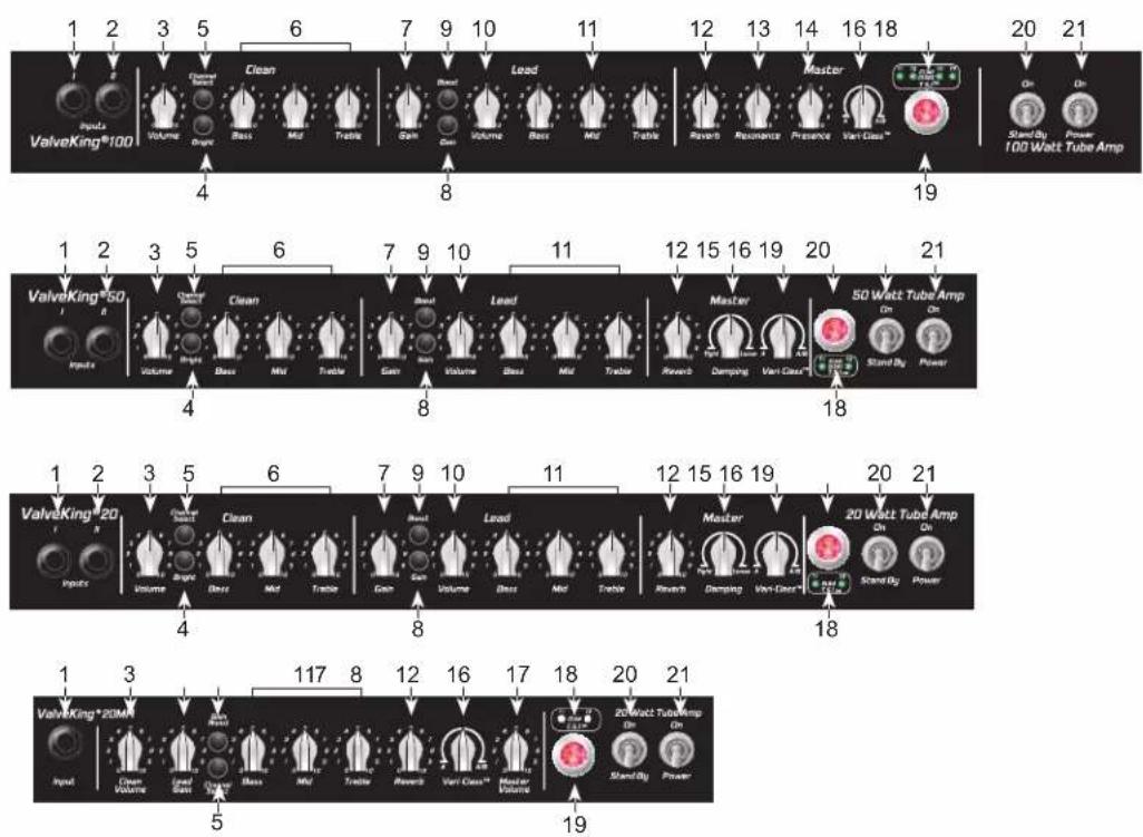
Front Panel
flowchart
graph TD
    A["ValveKing®100"] --> B["Inputs"]
    B --> C["Voltage"]
    C --> D["Clean"]
    D --> E["Bass"]
    E --> F["Mid"]
    F --> G["Tackle"]
    G --> H["Gain"]
    H --> I["Cash"]
    I --> J["Volume"]
    J --> K["Bass"]
    K --> L["Mid"]
    L --> M["Tackle"]
    M --> N["Reverb"]
    N --> O["Resonance"]
    O --> P["Presence"]
    P --> Q["Vant Class™"]
    Q --> R["Stand By"]
    R --> S["Power"]
    S --> T["100 Watt Tube Amp"]

    U["ValveKing®50"] --> V["Inputs"]
    V --> W["Voltage"]
    W --> X["Bass"]
    X --> Y["Mid"]
    Y --> Z["Tackle"]
    Z --> AA["Gain"]
    AA --> AB["Cash"]
    AB --> AC["Volume"]
    AC --> AD["Bass"]
    AD --> AE["Mid"]
    AE --> AF["Tackle"]
    AF --> AG["Reverb"]
    AG --> AH["Damping"]
    AH --> AI["Vant Class™"]
    AI --> AJ["Stand By"]
    AJ --> AK["Power"]

    AL["ValveKing®20"] --> AM["Inputs"]
    AM --> AN["Voltage"]
    AN --> AO["Bass"]
    AO --> AP["Mid"]
    AP --> AQ["Tackle"]
    AQ --> AR["Gain"]
    AR --> AS["Cash"]
    AS --> AT["Volume"]
    AT --> AU["Bass"]
    AU --> AV["Mid"]
    AV --> AW["Tackle"]
    AW --> AX["Reverb"]
    AX --> AY["Damping"]
    AY --> AZ["Vant Class™"]
    AZ --> BA["Stand By"]
    BA --> BB["Power"]

    BC["ValveKing®20M"] --> BD["Inputs"]
    BD --> BE["Voltage"]
    BE --> BF["Bass"]
    BF --> BG["Mid"]
    BG --> BH["Tackle"]
    BH --> BI["Reverb"]
    BI --> BJ["Vant Class™"]
    BJ --> BK["Stand By"]
    BK --> BL["Power"]

    BM["20 Watt Tube Amp"] --> BN["On"]
    BN --> BO["On"]

    BP["19 Watt Tube Amp"] --> BQ["On"]

    BQ --> BR["Stand By"]

    style A fill:#f9f,stroke:#333
    style B fill:#f9f,stroke:#333
    style C fill:#f9f,stroke:#333
    style D fill:#f9f,stroke:#333
    style E fill:#f9f,stroke:#333
    style F fill:#f9f,stroke:#333
    style G fill:#f9f,stroke:#333
    style H fill:#f9f,stroke:#333
    style I fill:#f9f,stroke:#333
    style J fill:#f9f,stroke:#333
    style K fill:#f9f,stroke:#333
    style L fill:#f9f,stroke:#333
    style M fill:#f9f,stroke:#333
    style N fill:#f9f,stroke:#333
    style O fill:#f9f,stroke:#333
    style P fill:#f9f,stroke:#333
    style Q fill:#f9f,stroke:#333
    style R fill:#f9f,stroke:#333
    style S fill:#f9f,stroke:#333
(1) INPUT I
Used for most electric guitars. It is 10 dB louder than INPUT II.
(2) INPUT II (not on ValveKing® 20MH)
Provided for instruments that have extremely high outputs, which can result in overdriving (distorting) INPUT I. If both inputs are used simultaneously, the levels are the same (both are high gain like INPUT I).
(3) VOLUME
Controls the volume level of the Clean channel.
(4) BRIGHT SWITCH (not on 20MH)
Provides a boost to treble frequencies. To activate, depress the switch to its "IN" position. The ValveKing® 20MH instead has a certain amount of brightness voiced into the Clean channel.
(5) CHANNEL SELECT SWITCH
Allows selection of the Lead or Clean channel. The "IN" position of the switch selects the Lead channel and the "OUT" position selects Clean.
NOTE: Channel selection may also be achieved by using an optional remote dual latching footswitch. If remote selection is desired, the CHANNEL SWITCH (#5) must be in the "IN" (Lead) position.
(6) BASS, MIDDLE AND TREBLE EQ (not on 20MH)
Passive tone controls that regulate the low, mid and high frequencies of the Clean channel. In the case of the ValveKing® 20MH, the tone of both channels is controlled by the tone controls mentioned in section #11.
(7) GAIN
Controls the input volume level of the Lead channel and the amount of overdrive.
(8) GAIN (GAIN BOOST on 20MH)
Acts as an extension to the GAIN control (#7). When depressed, this switch increases the preamp gain to add more distortion. The GAIN boost (#8) may be selected independently or in conjunction with the volume BOOST (#9) (except on 20MH). This feature can also be controlled via an optional remote dual latching footswitch.
NOTE: Activating this feature is comparable to turning up the Gain control, thus increasing distortion.
(9) BOOST (not on 20MH)
Acts as an extension to the VOLUME control (#10). When depressed, this switch boosts the overall volume level of the Lead channel. The volume BOOST may be selected independently or in conjunction with the GAIN boost (#8). This feature can be controlled via the same optional remote dual latching footswitch mentioned earlier.
NOTE: Activating this feature is comparable to turning up the VOLUME control, thus increasing loudness. It has more apparent effect in the middle areas of the VOLUME controls range.
In the case of the ValveKing ^® 20MH, a certain amount of volume boost is already voiced into the circuit when GAIN (#8) is selected.
(10) VOLUME (not on 20MH)
Controls the overall output level of the Lead channel.
(11) BASS, MIDDLE AND TREBLE EQ
Passive tone controls that regulate the low, mid and high frequencies of the Lead channel. In the case of the ValveKing® 20MH these control the tone of both channels.
(12) REVERB
Controls the overall reverb level. Fully counterclockwise will be completely dry with no reverb, low settings will produce subtle reverb and high settings will produce lush ambience. This feature can also be controlled via a second optional remote dual latching footswitch.
(13) RESONANCE (ValveKing® 100 Head only)
This patented feature, available only from Peavey, is used to fine-tune the low-frequency response and damping factor of the power amp section. At higher settings, the speakers are allowed to move more freely at low frequencies, resulting in more apparent low end with slightly less signal clarity at maximum settings.
(14) PRESENCE (ValveKing® 100 Head only)
This control is used to fine-tune the high-frequency response and damping factor of the power amp section. At higher settings, the speakers are allowed to move more freely at high frequencies, resulting in more apparent high end.
(15) DAMPING (ValveKing® 20 and 50 Combos only)
This control is used to fine-tune the overall response and damping factor of the power amp section. At higher settings, the speakers are allowed to move more freely, resulting in more apparent low and high end. Lower settings will produce a tighter sound.
(16) VARI-CLASS™
This patented feature available only from Peavey is used to fine-tune the power sensitivity, response and "break-up" of the power amp section of your ValveKing® amplifier. Normal, full-power, Class A/B operation results when the VARI-CLASS™ control is set at its fully clockwise position and should be used as a starting point when setting this control. As the VARI-CLASS™ control is rotated counterclockwise, the effect of one half of the power tubes is progressively subtracted from the circuit, while the gain of the driver tube is slowly increased. The driver's low-frequency response is also altered along with the gain, resulting in more even-order harmonic distortion from your power amp, even at lower-than-stage-volume settings. Finally, with the VARI-CLASS™ knob in the fully counterclockwise position, the result is a real single-ended power amp section that operates and responds exactly like a true Class A power amp, driven by a real single-ended high-gain tube stage.
This setting still allows the unused power tube(s) to draw idle current, thus retaining the efficiency of the standard Class A/B topology. In this mode, power output is also reduced by as much as 60% versus maximum rated power.
(17) MASTER VOLUME (ValveKing® 20MH only)
Controls the overall output level of the amplifier on both channels. The tone and balance between the two channels can be set by VOLUME (#3) and GAIN (#7), then the playing volume can be set as desired by the MASTER VOLUME (#17).
(18) TUBE STATUS INDICATION (T.S.I™) LEDS
These are LEDs that light green or red depending on the status of the power tube they are representing. These are merely the visual part of the wider status indication, fault detection and tube protection circuits. All models have one LED for each power tube, therefore all have two except for the ValveKing® 100 which has four due to it having four power tubes. From left to right these LEDs are associated with the corresponding power tube in the chassis.
The simple explanation is that the LED will be green in normal working mode and red in any other mode including: Standby, low bias, low current (tube wearing out) or high current fault condition that has switched on the protection circuit.
The more detailed explanation is as follows:
(This applies to all models but see below for important differences on ValveKing® 100.)
At Standby the LEDs should be red. This is due to the tubes not yet being fully on. When switching from Standby to On these should then turn from red to green. These should basically remain green in normal playing conditions.
If one or more LEDs goes red it means that tube is not working properly for one of the following reasons:
- Tube is ‘under current’: This could be due to incorrect bias, low current due to aging, open circuit due to structural/physical fault or missing filament heater supply.
- Tube has gone ‘over current’: In this case the resettable protection circuit will be switched on to protect against further damage and to allow the amplifier to carry on working with the remaining tube(s). This could be due to bias failure, over-heating of the tube or other fault condition resulting in excessive current draw.
Reset: In some conditions, with an adequate gap in playing, the protection circuit will auto-reset and allow the tube to be turned back on. If the fault remains then the LED will stay red. In these situations, at a convenient point the amp should be turned off for a few minutes then back on again. If the fault is still there then the amp should be checked by a factory authorized technician for correct bias or faulty/worn out tube(s).
Differences on ValveKing® 100:
In the normal ‘100% power’ and ‘speaker enabled’ modes, this will work exactly the same as mentioned earlier. However, as the 25% and 5% power modes as well as the speaker defeat setting intentionally turns off one pair of power tubes (to reduce unnecessary heat), the inner two LEDs will be lit red when set to any of these settings. This is the T.S.I. ^™ circuit operating as it should, by indicating that these two tubes are not currently active.
(19) PILOT LIGHT
Illuminates when AC power is being supplied to the amp.
(20) STANDBY SWITCH
Placing this switch in the "Standby" position will effectively mute the amplifier while leaving the tube filaments on. Leave this switch in the "Standby" position for a minimum of one (1) minute after engaging the POWER SWITCH (#21). This is also a useful feature because much tube wear comes from the heating and cooling of the tube itself. Leaving the unit in "Standby" when you take a break allows the tubes to stay warm while you are not playing. To immediately resume normal amp operation with no warm-up delay, place the switch in the "ON" position. NOTE: This switch does not replace the POWER SWITCH (#21). When you are ready to stop playing for an extended period of time, it is better to turn the amp off via the POWER SWITCH (#21). To prevent any undesirable noise, it is recommended to switch the amp to Standby for at least a few seconds before switching fully off.
(21) POWER SWITCH
To apply power to the unit, flip the switch to the "ON" position. The red PILOT LIGHT (#19) will illuminate, indicating power is being supplied.


Rear Panel
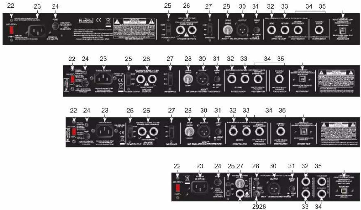
(22) VOLTAGE SELECTOR SWITCH
This selects between two different AC line/mains voltages. This should not normally need to be adjusted by the user, hence why it is covered with a clear plastic shield. This should already be set to the correct line/ mains voltage in your country/territory.
(23) AC POWER INLET:
This is the receptacle for an IEC line cord, which provides AC power to the unit. Connect the line cord to this connector to provide power to the unit. Damage to the equipment may result if improper line voltage is used. (See VOLTAGE SELECTOR SWITCH #22).
Never break off the ground pin on any equipment. It is provided for your safety. If the outlet used does not have a ground pin, a suitable grounding adapter should be used and the third wire should be grounded properly. To prevent the risk of shock or fire hazard, always make sure that the amplifier and all associated equipment is properly grounded.
NOTE: FOR UK ONLY
As the colours of the wires in the mains lead of this apparatus may not correspond with the coloured markings identifying the terminals in your plug, proceed as follows: (1) The wire which is coloured green and yellow must be connected to the terminal which is marked by the letter E, or by the Earth symbol, or coloured green or green and yellow. (2) The wire which is coloured blue must be connected to the terminal which is marked with the letter N, or the colour black. (3) The wire which is coloured brown must be connected to the terminal which is marked with the letter L, or the colour red.
To avoid the risk of electrical shock, do not place fingers or any other objects into empty tube sockets while power is being supplied to unit.
(24) FUSE
The fuse is located within the cap of the fuse holder. If the fuse should fail, IT MUST BE REPLACED WITH THE SAME TYPE AND VALUE IN ORDER TO AVOID DAMAGE TO THE EQUIPMENT AND TO PREVENT VOIDING THE WARRANTY. If the amp repeatedly blows fuses, it should be taken to a factory authorized center for repair.
WARNING: THE FUSE SHOULD ONLY BE REPLACED WHEN THE POWER CORD HAS BEEN DISCONNECTED FROM ITS POWER SOURCE.


(25) POWER OUTPUT SWITCH
This three position switch controls an attenuator which allows the maximum output of each amplifier to be switched between 100%, 25% and 5% of rated power. Therefore on the 100 head this would be 100W, 25W and 5W, on the 50 combo this would be 50W, 12W and 2W and on both the 20 combo and 20MH it would switch between 20W, 5W and 1W.
This enables the user to drive the power stage hard, therefore producing the characteristic power amp overdrive, but without such loud volumes produced by the speaker.
On the lower settings it may be necessary to slightly increase the Resonance, Presence and/or Damping controls for the desired tone. This is due to the change in damping factor when the speaker is driven less.
(26) SPEAKER OUTPUT(S)
Provided for connection to either the internal speaker (20 and 50 model combos) or external speaker cabinet(s).
Load impedance is selectable via the IMPEDANCE SELECTOR (27).
(27) IMPEDANCE SELECTOR
This switch allows appropriate selection of speaker/cabinet impedance. On the 100 head, 50 combo and 20 combo a three position switch is provided to allow selection of either 16Ω, 8Ω or 4Ω speaker/cabinet impedances. On the 20MH a two position toggle switch is provided to allow selection of either 16Ω or 8Ω speaker/cabinet impedances.
If two enclosures of equal impedance are used, the switch should be set to half the individual value. For example, two 16Ω enclosures necessitate an 8Ω setting, while two 8Ω enclosures would require a 4Ω setting.
Minimum speaker impedance is 4 on the 100 head, 50 combo and 20 combo, 8 on the 20MH.
(28) SPEAKER ENABLE/DEFEAT SWITCH
This effectively disconnects any speaker/cabinet connected to the SPEAKER OUTPUT(S) (#26). This enables the user to monitor their playing using the signal from either the MSDI™ output, USB output or headphone output (20MH only). Therefore they can play or record at much lower volume levels.
This is done safely as, instead of being loaded by the speaker, the tube power amplifier is loaded by an internal dummy load.
(29) HEADPHONE OUTPUT (20MH only)
This is for connection to normal headphones/earphones via a stereo mini-jack allowing the user to set the amp to the SPEAKER DISABLE position and practice silently. The signal is derived in the MSDI ^™ circuit (see below), therefore is filtered for a 12" guitar speaker-like tone.
(30) MIC SIMULATED DIRECT INTERFACE - MSDI™
Peavey's exclusive MSDI™ simulates the sound of a microphone placed approximately 8" from a loudspeaker cone, allowing the user to send an accurate, good quality signal to the mixing console without any acoustic spill from other instruments on stage. This is a non-powered output and safe for use with any mixing console.
(31) GROUND LIFT
Engage this switch if the mix engineer is hearing a hum in the MSDI™ output. This should eliminate the hum by removing the ground loop.
(32) EFFECTS LOOP SEND
1/4" output jack for supplying signals to external low-level effects or signal processing equipment.
(33) EFFECTS LOOP RETURN
1/4" input for returning signals from external low-level effects or signal processing equipment. This is a switching jack. Inserting a plug into this jack will break the signal path until it is returned via the EFFECTS SEND (#32) jack.
If the effects loop is used then it will automatically be on if a footswitch is not used. However, the effects loop can by bypassed by using an optional remote dual latching footswitch.
(34) FOOTSWITCH JACKS
Provided for the connection of the optional remote dual latching footswitches.
One dual footswitch can be used to select the Lead or Clean CHANNEL: the switch connected to the 'ring' of the jack (left on a Peavey footswitch), and to activate/defeat the GAIN or BOOST (#8 & #9): the switch connected to the 'tip' of the jack (right on a Peavey footswitch),
Additionally another dual footswitch can be used to turn the EFFECTS LOOP on and off: the switch connected to the 'ring' of the jack (left on a Peavey footswitch), and REVERB on and off: the switch connected to the 'tip' of the jack (right on a Peavey footswitch),
Peavey footswitches are available with and without LEDs to indicate current settings. Please refer to www.peavey.com or customer service for more information and product codes.
To footswitch CHANNEL, GAIN or BOOST the relevant front panel switches need to be set to their "IN" position. The BOOST footswitch turns on and off either or both GAIN or BOOST functions, as selected by the front panel switches. If no switch is depressed then the BOOST footswitch does not function.
In the case of the ValveKing® 20MH, a certain amount of volume boost, as well as gain, is voiced into the circuit when GAIN (#8) is selected. This is also available as a slight volume boost on the Clean channel, and can also be footswitched, further increasing the versatility, despite its compact design.
When using a footswitch, always insert the plug fully (second click) into the FOOTSWITCH jacks to ensure proper operation.
(35) MICROPHONE SIMULATED USB AUDIO RECORD OUTPUT
The ValveKing® USB Record Output requires no additional drivers – just plug a standard USB 2.0 cable into your computer and it will detect it as an audio device. Open your favorite recording program and start recording. The output is derived from the MSDI™ so will sound great right into your computer.
This can be used in any setting of the POWER OUTPUT (#25) or SPEAKER DEFEAT (#28) switches and there should be little comparative difference in USB audio level. Therefore a good strong signal can still be recorded while the amp is set to 5% power or even silent.
The actual level of the signal from the USB out will be dependent on the settings of the controls. However, each unit has been calibrated so that a very wide range of sounds and levels will all fit within the USB headroom. Like with any recording, especially digital, the actual recording levels should be set so as to prevent any unwanted distortion.
Power tubes
As mentioned earlier, the ValveKing® 100 and ValveKing® 50 can use either 6L6GC or EL34 power tubes. The design and all the relevant components have been chosen/upgraded so they can handle both types. The choice of which is often dependant on personal taste. Due to their slightly higher gain, EL34's will likely produce about 10 - 15% more power.
WARNING!!! If the power tubes are changed then the amplifier MUST be re-biased. We have designed them so this is a fairly quick and easy procedure, but this should be carried out by a qualified and competent technician/engineer. This is not only due to safety, but also to ensure the user gets the best sound and longevity from their new tubes. Incorrectly biased power tubes can either sound dirty and lifeless or burn out unnecessarily quickly.
ValveKing® 100
Rated Power: 100 W (rms) into 4, 8 or 16Ω
Power Consumption: (Domestic) 275 W, 50/60 Hz, 120 VAC
Tube Complement: 4 x 6L6GC, 3 x 12AX7/ECC83
Dimensions (HxWxD): 9.75" x 26.50" x 11.13" / 248 mm x 673 mm x 283 mm
Weight: 38 lbs / 17 kg
ValveKing® 50
Rated Power: 50 W (rms) into 4, 8 or 16Ω
Power Consumption: (Domestic) 160 W, 50/60 Hz, 120 VAC
Tube Complement: 2 x 6L6GC, 3 x 12AX7/ECC83
Dimensions (HxWxD): 20.50" x 22.00" x 10.2 / 521 mm x 559 mm x 260 mm
Weight: 40.6 lbs / 18 kg
ValveKing® 20
Rated Power: 20 W (rms) into 4, 8 or 16Ω
Power Consumption: (Domestic) 90 W, 50/60 Hz, 120 VAC
Tube Complement: 2 x EL84, 3 x 12AX7/ECC83
Dimensions (HxWxD): 20.50" x 22.00" x 10.25" / 521 mm x 559 mm x 260 mm
Weight: 37.6 lbs / 17 kg
ValveKing® 20MH
Rated Power: 20 W (rms) into 8 or 16Ω
Power Consumption: (Domestic) 90 W, 50/60 Hz, 120 VAC
Tube Complement: 2 x EL84, 3 x 12AX7/ECC83
Dimensions (HxWxD): 7.25" x 14.00" x 7.75 / 184 mm x 356 mm x 197 mm
Weight: 14.6 lbs / 7 kg
ValveKing® Series 100/50/20/20MH Preamp Specifications
Preamp High Gain Input:
Impedance: Very High-Z, 1MΩ
Preamp Low Gain Input: (-10 dB Pad)
Impedance: High-Z, 68 kΩ
Effects Send:
Low Impedance: High-Z, 22 kΩ or greater
Nominal Output Level: o dBV, 1.0 V (rms)
Effects Return:
Impedance: Very High-Z, 1 MΩ
Designed Input Level: o dBV, 1.0 V (rms)
Equalization: (Clean channel only)
Custom Low, Mid, & High passive EQ
Push Bright: +6dB @ \~3.5kHz
Equalization: (Lead channel and 20MH)
Custom Low, Mid, & High passive EQ
Lead Channel Front Panel Footswitch Functions:
Push Gain: Increase Gain in Lead channel and introduces a tighter low end response.
Push Volume: +3-5dB Volume boost (more effect at midway Lead Volume settings)
Remote Footswitch (s): (optional)
One or two dual latching footswitches.
One footswitch for channel selection and Volume Boost and/or Gain Boost functions preset on the front panel GAIN (8) and VOLUME (9) switches described earlier.
A second footswitch can be used for switching REVERB and EFFECTS LOOP on and off.
Other Misc Specifications
Signal to Noise Ratio:
Better than 74dB on all models (compared to full power)
MSDI™ Output:
Low Impedance: 600Ω Balanced
Output Level: Dependent on controls but -12dBu (+/-3dBu) at full power on all models
USB Output:
Output Level: Dependent on controls but -6dB (+/-3dB) at full power on all models
Power attenuator:
Three setting switch for 100% (bypassed), 25% and 5% of rated power
Headphone Output: (20MH only)
Stereo mini-jack with filtered output for driving stereo headphones, 16Ω - 50Ω impedance per channel.
Features and specifications subject to change without notice.
FRANÇAIS
ValveKing® série 100/50/20/20MH
As the colours of the wires in the mains lead of this apparatus may not correspond with the coloured markings identifying the terminals in your plug, proceed as follows: (1) The wire which is coloured green and yellow must be connected to the terminal which is marked by the letter E, or by the Earth symbol, or coloured green or green and yellow. (2) The wire which is coloured blue must be connected to the terminal which is marked with the letter N, or the colour black. (3) The wire which is coloured brown must be connected to the terminal which is marked with the letter L, or the colour red.
To avoid the risk of electrical shock, do not place fingers or any other objects into empty tube sockets while power is being supplied to unit.
(24) FUSIBLE
As the colours of the wires in the mains lead of this apparatus may not correspond with the coloured markings identifying the terminals in your plug, proceed as follows: (1) The wire which is coloured green and yellow must be connected to the terminal which is marked by the letter E, or by the Earth symbol, or coloured green or green and yellow. (2) The wire which is coloured blue must be connected to the terminal which is marked with the letter N, or the colour black. (3) The wire which is coloured brown must be connected to the terminal which is marked with the letter L, or the colour red.
To avoid the risk of electrical shock, do not place fingers or any other objects into empty tube sockets while power is being supplied to unit.
(24) SICHERUNG
(11) BASS, MIDDLE E TREBLE EQ
(18) INDICATORE STATO TUBO (LED T.S.I.™)
As the colours of the wires in the mains lead of this apparatus may not correspond with the coloured markings identifying the terminals in your plug, proceed as follows: (1) The wire which is coloured green and yellow must be connected to the terminal which is marked by the letter E, or by the Earth symbol, or coloured green or green and yellow. (2) The wire which is coloured blue must be connected to the terminal which is marked with the letter N, or the colour black. (3) The wire which is coloured brown must be connected to the terminal which is marked with the letter L, or the colour red.
To avoid the risk of electrical shock, do not place fingers or any other objects into empty tube sockets while power is being supplied to unit.
(24) FUSIBILE
(26) USCITE ALTOPARLANTE
As the colours of the wires in the mains lead of this apparatus may not correspond with the coloured markings identifying the terminals in your plug, proceed as follows: (1) The wire which is coloured green and yellow must be connected to the terminal which is marked by the letter E, or by the Earth symbol, or coloured green or green and yellow. (2) The wire which is coloured blue must be connected to the terminal which is marked with the letter N, or the colour black. (3) The wire which is coloured brown must be connected to the terminal which is marked with the letter L, or the colour red.
To avoid the risk of electrical shock, do not place fingers or any other objects into empty tube sockets while power is being supplied to unit.
(24) FUSIBLE
(8) GAIN (GAIN BOOST on 20MH)
(11) BASS, MIDDLE E TREBLE EQ
As the colors of the wires in the mains lead of this apparatus may not correspond with the colored markings identifying the terminals in your plug, proceed as follows: (1) The wire that is colored green and yellow must be connected to the terminal that is marked by the letter E, or by the Earth symbol, or colored green or green and yellow. (2) The wire that is colored blue must be connected to the terminal that is marked with the letter N, or the color black. (3) The wire that is colored brown must be connected to the terminal that is marked with the letter L, or the color red.
To avoid the risk of electrical shock, do not place fingers or any other objects into empty tube sockets while power is being supplied to unit.
(24) FUSÍVEL
Empurrar Bright: +6dB @ \~3.5kHz
As the colours of the wires in the mains lead of this apparatus may not correspond with the coloured markings identifying the terminals in your plug, proceed as follows: (1) The wire which is coloured green and yellow must be connected to the terminal which is marked by the letter E, or by the Earth symbol, or coloured green or green and yellow. (2) The wire which is coloured blue must be connected to the terminal which is marked with the letter N, or the colour black. (3) The wire which is coloured brown must be connected to the terminal which is marked with the letter L, or the colour red.
To avoid the risk of electrical shock, do not place fingers or any other objects into empty tube sockets while power is being supplied to unit.
(24) 熔断器
As the colours of the wires in the mains lead of this apparatus may not correspond with the coloured markings identifying the terminals in your plug, proceed as follows: (1) The wire which is coloured green and yellow must be connected to the terminal which is marked by the letter E, or by the Earth symbol, or coloured green or green and yellow. (2) The wire which is coloured blue must be connected to the terminal which is marked with the letter N, or the colour black. (3) The wire which is coloured brown must be connected to the terminal which is marked with the letter L, or the colour red.
To avoid the risk of electrical shock, do not place fingers or any other objects into empty tube sockets while power is being supplied to unit.
(24) ヒューズ
Effective Date: 11/01/2011
What This Warranty Covers
Your Peavey Warranty covers defects in material and workmanship in Peavey products purchased and serviced in the U.S.A. and Canada.
What This Warranty Does Not Cover
The Warranty does not cover: (1) damage caused by accident, misuse, abuse, improper installation or operation, rental, product modification or neglect; (2) damage occurring during shipment; (3) damage caused by repair or service performed by persons not authorized by Peavey; (4) products on which the serial number has been altered, defaced or removed; (5) products not purchased from an Authorized Peavey Dealer.
Who This Warranty Protects
This Warranty protects only the original purchaser of the product.
How Long This Warranty Lasts
The Warranty begins on the date of purchase by the original retail purchaser. The duration of the Warranty is as follows:
| Product Category Duration | |
| Guitars/Basses, Amplifiers, Preamplifiers, Mixers, Electronic Crossovers and Equalizers 2 years *(+ 3 years) | |
| Drums 2 years *(+ 1 year) | |
| Enclosures 3 years *(+ 2 years) | |
| Digital Effect Devices and Keyboards and MIDI Controllers 1 years *(+ 1 year) | |
| Microphones 2 years | |
| Speaker Components(incl. Speakers, Baskets, Drivers, Diaphragm Replacement Kits and Passive Crossovers) | 1 year |
| Tubes and Meters | 90 Days |
| Cables Limited Lifetime | |
| AmpKit Link, Xport, Rockmaster Series, Strum'n Fun, RetroFire, GT & BT Series Amps | 1 year |
| Marvel Jr. Guitar | 90 Days |
[* Denotes additional Warranty period applicable if optional Warranty Registration Card is completed and returned to Peavey by original retail purchaser within 90 days of purchase.]
What Peavey Will Do
We will repair or replace (at Peavey's discretion) products covered by Warranty at no charge for labor or materials. If the product or component must be shipped to Peavey for Warranty service, the consumer must pay initial shipping charges. If the repairs are covered by Warranty, Peavey will pay the return shipping charges.
How To Get Warranty Service
(1) Take the defective item and your sales receipt or other proof of date of purchase to your Authorized Peavey Dealer or Authorized Peavey Service Center.
OR
(2) Ship the defective item, prepaid, to Peavey Electronics Corporation, International Service Center, 412 Highway 11 & 80 East, Meridian, MS 39301. Include a detailed description of the problem, together with a copy of your sales receipt or other proof of date of purchase as evidence of Warranty coverage. Also provide a complete return address.
Limitation of Implied Warranties
ANY IMPLIED WARRANTIES, INCLUDING WARRANTIES OF MERCHANTABILITY AND FITNESS FOR A PARTICULAR PURPOSE, ARE LIMITED IN DURATION TO THE LENGTH OF THIS WARRANTY.
Some states do not allow limitations on how long an implied Warranty lasts, so the above limitation may not apply to you.
Exclusions of Damages
PEAVEY'S LIABILITY FOR ANY DEFECTIVE PRODUCT IS LIMITED TO THE REPAIR OR REPLACEMENT OF THE PRODUCT, AT PEAVEY'S OPTION. IF WE ELECT TO REPLACE THE PRODUCT, THE REPLACEMENT MAY BE A RECONDITIONED UNIT. PEAVEY SHALL NOT BE LIABLE FOR DAMAGES BASED ON INCONVENIENCE, LOSS OF USE, LOST PROFITS, LOST SAVINGS, DAMAGE TO ANY OTHER EQUIPMENT OR OTHER ITEMS AT THE SITE OF USE, OR ANY OTHER DAMAGES WHETHER INCIDENTAL, CONSEQUENTIAL OR OTHERWISE, EVEN IF PEAVEY HAS BEEN ADVISED OF THE POSSIBILITY OF SUCH DAMAGES.
Some states do not allow the exclusion or limitation of incidental or consequential damages, so the above limitation may not apply to you.
This Warranty gives you specific legal rights, and you may also have other rights which vary from state to state.
If you have any questions about this Warranty or services received or if you need assistance in locating an Authorized Service Center, please contact the Peavey International Service Center at (601) 483-5365.
Features and specifications are subject to change without notice.
U.S. CUSTOMER WARRANTY REGISTRATION
Optional Product Extended Warranty Registration
Give us some information and put your extended warranty into effect!
Please take a few minutes to fill out this information/survey sheet to help us get to know and serve you better.
To save time, submit your warranty registration online at www.peavey.com/support/warrantyregistration
1.
First Name Initial Last Name
Street Address
City State/Province Postal Code
( )
Telephone Number E-mail Address
( ) - -
Fax Number Date of birth
Gender □M □F
2.
Model ____ Serial #
Date of Purchase Price Paid
3.
Name of store where purchased
City State
- Top two (2) reasons why you purchased from this store/dealer:
| Availability of productFriend/Relative's recommendationStore credit cardKnowledgeable staffAvailability of lessonsTechnical instruction | Past favorable experienceBest priceAdvertised specialConvenient locationReceived as a giftOther ____ |
- Where do you most often shop for music and sound products?
□ Independent retailer □ Newspaper ads
□ Mass market retailer □ Internet/Web sites
□ Mail order magazines □ Other
- What two (2) factors most influenced your purchase of this product?
☐ Peavey brand name ☐ Product appearance
□ Craftsmanship □ Durability
□ Features for price □ Prior experience with Peavey
☐ Bundled accessories ☐ Packaging
☐ Sound quality ☐ Other
- How did you learn about this Peavey product? (select best answer)
| □ Magazine review | □ Teacher's recommendation |
| □ Newspaper review | □ Catalog or flyer |
| □ Radio advertisement | □ Saw in store |
| □ Advertised special | □ Use by professional |
| □ Friend/Relative's recommendation | □ Other ____ |
| □ Salesperson's recommendation |
-
Which other brands/models did you consider?
-
How would you describe your level of musicianship/technical expertise?
☐ Beginner - Never played or taken less than one (1) year of lessons
☐ Intermediate - One (1) to five (5) years of lessons or playing
□ Advanced - More than five (5) years of lessons or playing; play professionally
- Education: (select best answer)
□ High school
Some college
□ Completed college
□ Graduate school
- Which best describe your family income? (select best answer)
☐ Under \15,000 ☐ \75,000 - \$99,999
□ \15,000 - \24,999 □ \100,000 - \149,999
□ \25,000 - \34,999 □ Over - \$150,000
□ \35,000 - \49,999
□ \50,000 - \74,999
- Which of the following is your primary source of information on musical products: (select best answer)
□ Television □ Mail order catalogs
☐ Radio ☐ Direct mail
□ Internet □ Literature from manufacturer
□ Newspaper □ Other ____
□ Magazines
- What is your main motivation for buying new equipment?
□ Replacing old product □ Impulse
□ Want new and leading edge □ Need for improved performance
equipment □ New technology
☐ Fullfill a specific need ☐ Availability of product
□ Supplement existing products □ Other ____
Value
-
Please list your three most frequently visited Web sites.
-
http://
-
http://
-
http://
-
In your opinion, what could Peavey do to improve its products and/or service? Please use the space below to tell us your answer.
Revised 1/11
Thank you for taking the time to fill out our survey! Don't forget to fold and tape (with Peavey address facing out), affix postage stamp and drop in the mail!

Logo referenced in Directive 2002/96/EC Annex IV (CJ1)37/89-10-33-99
(CJ(L)37/38,13.02.03 and defined in EN 50419: 2005
The bar is the symbol for marking of new waste and
s applied only to equipment manufactured after
13 August 2005
Meridian, Ms 39302-5108
P.O. Box 5108
Attn: Warranty Department
Corporation
Peavey Electronics

natural_image
Abstract black geometric logo design with stylized arrow-like shapes (no text or symbols)Here Postage Place

- IMPORTANT SAFETY INSTRUCTIONS
- FCC Compliancy Statement
- ValveKing® 20MH & ValveKing® 100 Head
- ENGLISH
- ValveKing® Series 100/50/20/20MH
- FEATURES:
- Front Panel
- INPUT I
- INPUT II (not on ValveKing® 20MH)
- VOLUME
- BRIGHT SWITCH (not on 20MH)
- CHANNEL SELECT SWITCH
- BASS, MIDDLE AND TREBLE EQ (not on 20MH)
- GAIN
- GAIN (GAIN BOOST on 20MH)
- BOOST (not on 20MH)
- VOLUME (not on 20MH)
- BASS, MIDDLE AND TREBLE EQ
- REVERB
- RESONANCE (ValveKing® 100 Head only)
- PRESENCE (ValveKing® 100 Head only)
- DAMPING (ValveKing® 20 and 50 Combos only)
- VARI-CLASS™
- MASTER VOLUME (ValveKing® 20MH only)
- TUBE STATUS INDICATION (T.S.I™) LEDS
- The more detailed explanation is as follows:
- Differences on ValveKing® 100:
- PILOT LIGHT
- STANDBY SWITCH
- POWER SWITCH
- Rear Panel
- VOLTAGE SELECTOR SWITCH
- AC POWER INLET:
- NOTE: FOR UK ONLY
- FUSE
- POWER OUTPUT SWITCH
- SPEAKER OUTPUT(S)
- IMPEDANCE SELECTOR
- SPEAKER ENABLE/DEFEAT SWITCH
- HEADPHONE OUTPUT (20MH only)
- MIC SIMULATED DIRECT INTERFACE - MSDI™
- GROUND LIFT
- EFFECTS LOOP SEND
- EFFECTS LOOP RETURN
- FOOTSWITCH JACKS
- MICROPHONE SIMULATED USB AUDIO RECORD OUTPUT
- Power tubes
- ValveKing® 100
- ValveKing® 50
- ValveKing® 20
- ValveKing® 20MH
- ValveKing® Series 100/50/20/20MH Preamp Specifications
- Effects Send:
- Effects Return:
- Remote Footswitch (s): (optional)
- Other Misc Specifications
- Signal to Noise Ratio:
- MSDI™ Output:
- USB Output:
- Power attenuator:
- Headphone Output: (20MH only)
- FRANÇAIS
- ValveKing® série 100/50/20/20MH
- FUSIBLE
- SICHERUNG
- BASS, MIDDLE E TREBLE EQ
- INDICATORE STATO TUBO (LED T.S.I.™)
- FUSIBILE
- USCITE ALTOPARLANTE
- FUSÍVEL
- 熔断器
- ヒューズ
- What This Warranty Covers
- What This Warranty Does Not Cover
- Who This Warranty Protects
- How Long This Warranty Lasts
- What Peavey Will Do
- How To Get Warranty Service
- Limitation of Implied Warranties
- Exclusions of Damages
- U.S. CUSTOMER WARRANTY REGISTRATION
- Optional Product Extended Warranty Registration
- 1.
- 2.
- 3.
Brand : PEAVEY
Model : ValveKing 20 MH
Category : Audio Amplifier