
MMA 8752 - Audio Amplifier PEAVEY - Free user manual and instructions
Find the device manual for free MMA 8752 PEAVEY in PDF.
| Product Type | 9-channel audio mixer amplifier |
| Input Channels | 8 slots for MMA modules + dedicated Program input |
| Speaker Outputs | Direct output 4 Ω, isolated transformer outputs: 8 Ω, 25 V, 70 V, 100 V (model 8752) |
| Equalization | Bass and treble control with switch bypass |
| Low-cut filter | 60 Hz, switchable |
| Remote control | Volume via external potentiometer 10 kΩ (30 dB attenuation) or 100 kΩ (60 dB) |
| Mute bus | 2 Mute buses (Mute 1 and 2) with LED indicators |
| Protection | Thermal, short circuit, SPS (Speaker Protection System) with indicator |
| Power supply | Mains via IEC cable, fuse, on/off switch |
| Auxiliary output | Switched mains outlet 300 W max |
| Preamp output | Line level unaffected by tone and volume controls |
| Program input | Line level, controlled by Program level, muted by Mute 1 |
| Rack mounting | 19" rack ears included |
| Typical applications | Conference rooms, auditoriums, background music, restaurants, paging systems |
Frequently Asked Questions - MMA 8752 PEAVEY
User questions about MMA 8752 PEAVEY
0 question about this device. Answer the ones you know or ask your own.
Ask a new question about this device
Download the instructions for your Audio Amplifier in PDF format for free! Find your manual MMA 8752 - PEAVEY and take your electronic device back in hand. On this page are published all the documents necessary for the use of your device. MMA 8752 by PEAVEY.
USER MANUAL MMA 8752 PEAVEY
Intended to alert the user to the presence of uninsulated "dangerous voltage" within the product's enclosure that may be of sufficient magnitude to constitute a risk of electric shock to persons.

Intended to alert the user of the presence of important operating and maintenance (servicing) instructions in the literature accompanying the product.
CAUTION: Risk of electrical shock — DO NOT OPEN!
CAUTION: To reduce the risk of electric shock, do not remove cover. No user serviceable parts inside. Refer servicing to qualified service personnel.
WARNING: To prevent electrical shock or fire hazard, do not expose this appliance to rain or moisture. Before using this appliance, read the operating guide for further warnings.

WARNING: When using electrical products, basic cautions should always be followed, including the following:
- Read these instructions.
- Keep these instructions.
- Heed all warnings.
- Follow all instructions.
- Do not use this apparatus near water.
- Clean only with a dry cloth.
- Do not block any of the ventilation openings. Install in accordance with manufacturer's instructions.
- Do not install near any heat sources such as radiators, heat registers, stoves or other apparatus (including amplifiers) that produce heat.
- Do not defeat the safety purpose of the polarized or grounding-type plug. A polarized plug has two blades with one wider than the other. A grounding type plug has two blades and a third grounding plug. The wide blade or third prong is provided for your safety. If the provided plug does not fit into your outlet, consult an electrician for replacement of the obsolete outlet.
- Protect the power cord from being walked on or pinched, particularly at plugs, convenience receptacles, and the point they exit from the apparatus.
- Note for UK only: If the colors of the wires in the mains lead of this unit do not correspond with the terminals in your plug, proceed as follows:
a) The wire that is colored green and yellow must be connected to the terminal that is marked by the letter E, the earth symbol, colored green or colored green and yellow.
b) The wire that is colored blue must be connected to the terminal that is marked with the letter N or the color black.
c) The wire that is colored brown must be connected to the terminal that is marked with the letter L or the color red.
-
Only use attachments/accessories provided by the manufacturer.
-
Use only with a cart, stand, tripod, bracket, or table specified by the manufacturer, or sold with the apparatus. When a cart is used, use caution when moving the cart/apparatus combination to avoid injury from tip-over.
- Unplug this apparatus during lightning storms or when unused for long periods of time.
- Refer all servicing to qualified service personnel. Servicing is required when the apparatus has been damaged in any way, such as power-supply cord or plug is damaged, liquid has been spilled or objects have fallen into the apparatus, the apparatus has been exposed to rain or moisture, does not operate normally, or has been dropped.
- Never break off the ground pin. Write for our free booklet "Shock Hazard and Grounding." Connect only to a power supply of the type marked on the unit adjacent to the power supply cord.
- If this product is to be mounted in an equipment rack, rear support should be provided.
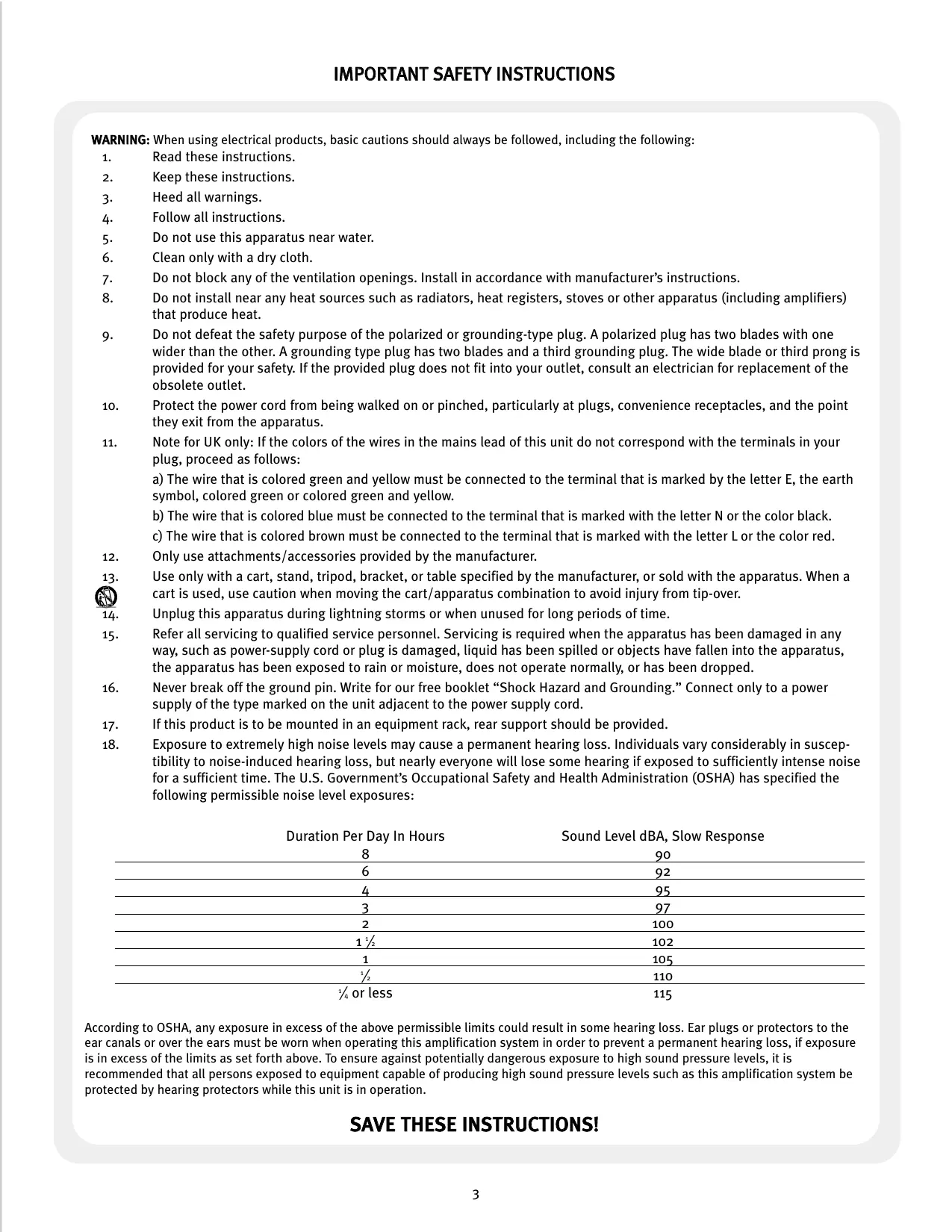
- Exposure to extremely high noise levels may cause a permanent hearing loss. Individuals vary considerably in susceptibility to noise-induced hearing loss, but nearly everyone will lose some hearing if exposed to sufficiently intense noise for a sufficient time. The U.S. Government's Occupational Safety and Health Administration (OSHA) has specified the following permissible noise level exposures:
| Duration Per Day In Hours | Sound Level dBA, Slow Response |
| 8 | 90 |
| 6 | 92 |
| 4 | 95 |
| 3 | 97 |
| 2 | 100 |
| 1 1/2 | 102 |
| 1 | 105 |
| 1/2 | 110 |
| 1/4 or less | 115 |
According to OSHA, any exposure in excess of the above permissible limits could result in some hearing loss. Ear plugs or protectors to the ear canals or over the ears must be worn when operating this amplification system in order to prevent a permanent hearing loss, if exposure is in excess of the limits as set forth above. To ensure against potentially dangerous exposure to high sound pressure levels, it is recommended that all persons exposed to equipment capable of producing high sound pressure levels such as this amplification system be protected by hearing protectors while this unit is in operation.
SAVE THESE INSTRUCTIONS!
ENGLISH
Description:
MMA™ Mixer/Power Amplifier Systems
The MMA™ 81502, 8752 and 8352 are high-quality, industrial-grade audio mixer/amplifiers. Designed for flexibility in application, these mixer/amps represent the latest, state-of-the-art technology in mixer/amplifier design. Powerful, yet easy to use, the MMA series delivers amazing sonic performance. Low-noise design and features applicable to "real world" situations make these units ideal for audio applications where a powerful, compact mixer/amplifier with multiple inputs and outputs are required.
This manual was written to provide as much information as possible for your new Peavey Architectural Acoustics product. It is our sincere desire that you enjoy your purchase.
We feel that the best way to fully enjoy any purchase is to have an in-depth understanding of the product's features, functionality and performance characteristics. We hope that this manual, along with the manuals of our other products, will provide this. If you require additional information not provided in this manual, please let us know. We are continuously looking for better ways to provide information about our products and your input is always appreciated.
If you have a comment about this manual or would like to make a suggestion, please write to: Peavey Electronics Corp., Architectural Acoustics Division, 711 A Street, Meridian MS 39301 or visit our website at: www.peavey.com. Thank you for using Peavey Architectural Acoustics!
Features:
- nine channel mixer/power amplifier system
- eight input ports accept MMA™ plug-in modules
- dedicated program input
high and low EQ controls - switchable low cut filter
external volume control capability - two mute buses
- preamp output/power amp input patch capability
- short circuit and thermal protection
- SPS™ (Speaker Protection System) circuitry with indicator
- 4 Ohm direct output
- 8 Ohm, 25 Volt, and 70 Volt transformer isolated power outputs (MMA81502 120V only)
- 8 Ohm, 70 Volt, and 100 Volt transformer isolated power outputs (MMA81502 230V only)
- 8 Ohm/25 Volt, 70 Volt, and 100 Volt transformer isolated power outputs (MMA8752)
- 8 Ohm, 70 Volt, and 100 Volt transformer isolated power outputs (MMA8352)
- AC convenience outlet (120V units only)
- optional rack mounting with included rack ears
Applications
- presentation rooms
- board rooms
courtrooms
auditoriums - lecture halls
-
meeting rooms
-
convention centers
- paging systems
- background music
- retail spaces
- restaurants
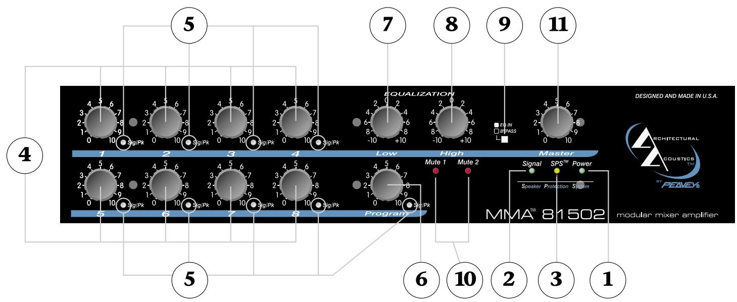
Front Panel
1. Power Indicator
The green LED indicates when AC power is supplied to the unit and the power switch is on.
2. Signal Level Indicator
The green LED indicates signal presence at the amplifier output.
3. SPS™ Indicator
The red LED indicates when SPS circuitry is active. SPS eliminates power amplifier clipping.
4. Input Channel Level Controls
Controls the signal level of the input channels 1-8 respectively to the mix bus.
5. Input Channel Signal Status Indicators
Indicates signal presence (green) and peak (red) conditions of the channel input signal prior to the level controls. Be cautious not to overdrive the mix bus.
6. Program Input Level Control
Controls the signal level of the program input to the mix bus.
7. Low EQ Control (Bass)
This is an active equalization control that adjusts the low frequency. Clockwise rotation boosts low frequencies and counter-clockwise rotation provides a cut in low frequencies (± 10 dB). EQ is flat at center detent.
8. High EQ Control (Treble)
This is an active equalization control that adjusts the high frequency. Clockwise rotation boosts high frequencies and counter-clockwise rotation provides a cut in high frequencies (±10 dB). EQ is flat at center detent.
9. EQ Bypass Switch
Selects the status of the EQ. When OUT the EQ controls are active. When IN the EQ controls are inactive and the EQ is flat.
10. Mute Bus Indicators
The red LEDs indicate the status of each mute bus. Each LED lights when its appropriate mute bus is activated.
11. Master Level Control
Controls the overall level of the system.
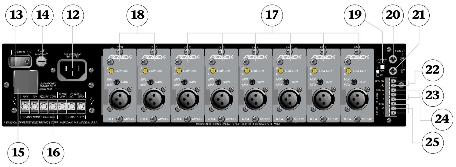
Rear Panel

12. AC Power Receptacle
This receptacle is for the IEC line cord (included) that provides AC power to the unit.
Never break off the ground pin on any equipment. It is provided for your safety. If the outlet used does not have a ground pin, a suitable grounding adapter should be used and the third wire should be grounded properly. To prevent the risk of shock or fire hazard, always be sure that the mixer and all other associated equipment are properly grounded.
13. Power Switch
This rocker switch applies mains power to the unit.
14. Fuse
The fuse is located within the cap of the fuse holder. If the fuse fails, THE FUSE MUST BE REPLACED WITH THE SAME TYPE AND VALUE IN ORDER TO AVOID DAMAGE TO THE EQUIPMENT AND TO PREVENT VOIDING THE WARRANTY. If the amp repeatedly blows fuse, it should be taken to a qualified service center for repair.
WARNING: The fuse should only be replaced when the power cord has been disconnected from its power source!
15. AC Outlet (Unswitched)
Provides AC power for auxiliary equipment with power consumption less than 300 Watts. This outlet is not controlled by the power switch (#13).
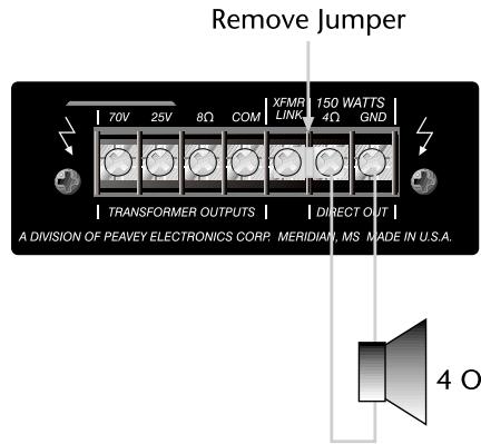
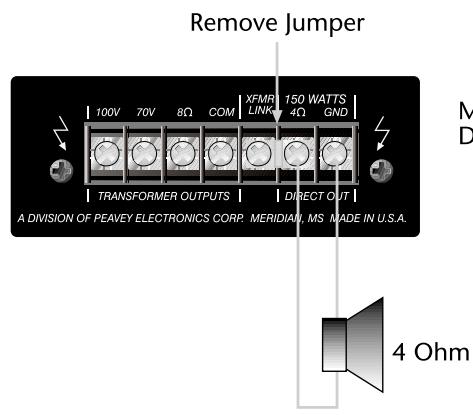
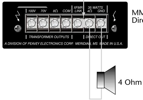
16. Outputs
A direct output and transformer isolated outputs are provided to allow proper interface between the amplifier and the loudspeaker system. The direct output allows connection to a 4 Ohm speaker system. To use this output, remove the jumper between the 4 Ohm terminal and the XFMR LINK terminal. Connect the loudspeaker system to the 4 Ohm and GND terminals.
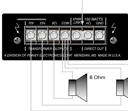
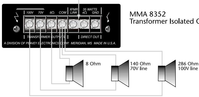
For transformer isolated outputs, ensure the jumper is inserted between the XFMR LINK terminal and the 4 Ohm terminal, then connect load between the desired output and COM. The Low Cut switch (#19) should be ON. See LOUDSPEAKER OUTPUT CONNECTIONS below for details.
17. Module Input Ports 1-6
Accepts optional PLUG-IN MODULES. The modules should be selected by installation requirements. These ports accept and support PLUG-IN MODULES that do not require a +5V power supply. For details, refer to the individual PLUG-IN MODULE Instruction Guide.
CAUTION: PLUG-IN MODULES should not be inserted or removed while the mixer/amplifier is turned on.
NOTE: No more than two of the optional OPM™ Output Power Modules may be used in each MMA mainframe.
18. Module Input Ports 7-8
Accepts optional PLUG-IN MODULES. The modules should be selected by installation requirements. These ports accept and support specific PLUG-IN MODULES that do require a +5V power supply, however any PLUG-IN MODULE may be utilized. For details, refer to the individual PLUG-IN MODULE Instruction Guide.
CAUTION: PLUG-IN MODULES should not be inserted or removed while the mixer/amplifier is turned on.
NOTE: No more than two of the optional OPM™ Output Power Modules may be used in each MMA mainframe.
19. Low cut switch
Provides a 6 dB/octave low frequency roll-off at 60Hz . To be used when the transformer isolated power outputs are connected to the loudspeaker system.
20. Preamplifier Out
Provides a line level output of Master Level mix output to drive external devices such as signal processors, hearing assistance systems, or recording equipment. The input impedance of the equipment should be greater than 600 Ohms.
21. Power Amplifier Input
Provides a direct input to the power amplifier with an input sensitivity of 1 Volt. When an RCA phono plug is inserted into this input, the connection between the preamp output and the power amp input is internally disconnected allowing direct access to the power amplifier. Using this input along with the preamplifier output (#9), a signal processor can be inserted between the mixer and the power amplifier.
22. Bridge In/Out
Provides an output signal that is independent of the Master level, Low EQ, and High EQ controls. It also may be used as a mixing output point when the similar terminal of another mixer/amplifier is connected to this terminal. A separate tape recorder output may be taken from this point without interaction of EQ and Master level control. The input impedance of the equipment connected to this terminal should be greater than 10k Ohms.
23. Program Input
Provides an auxiliary input that accepts signals from other sources such as another mixer or mixer/amplifier. The signal level at this input is controlled by the PROGRAM level control on the front panel and is fed to the mix bus. The Program input may be regarded as "Channel 9" without PLUG-IN MODULE capability.
NOTE: This input is muted whenever the Mute 1 bus is activated (#24).
24. Ext Mute 1/2
When either of these terminals is connected to the Shield terminal (SHD), the respective mute bus is activated and fed to any PLUG-IN MODULES utilizing its mating function. For details about the module's mating function, refer to the individual PLUG-IN MODULE Instruction Guide.
25. External Volume Control
These connections allow the use of an external (remote) master volume control. For complete command of the volume from the remote control, the front panel Master Level control (#1) must be set at its maximum (10) position. The remote volume control should be connected as shown in Figure 1, with the clockwise terminal connected to the Shield (SHD); the wiper connected to the Control (C); and the counterclockwise terminal connected to the Voltage (V). Using a 1ok Ohm linear taper potentiometer will provide approximately 30 dB attenuation, while using a 1ook Ohm linear taper potentiometer will provide approximately 60 dB attenuation. See Figure 1.
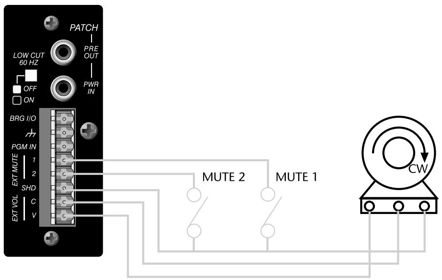
Figure 1
Potentiometer
10k Ohms for 30 dB attenu.
100k Ohms for 60 dB attenu.
External Volume Control connection limiting front panel master volume control range
Installing Rack-mount Ears
This unit can be rack-mounted in a standard EIA equipment rack with the two included rack ears. To attach the ears, simply remove the three screws already in the front of each side of the unit and align the ears with the appropriate mounting holes. It may be desirable to remove the rubber feet from the bottom of the unit when mounting in an equipment rack.
Note: To provide adequate ventilation, leave at least one rack space between units when multiple amplifiers are mounted in the same equipment rack. For proper operation of this unit, do not place within 6'' of any wall or combustible surface.
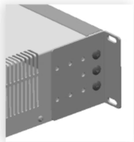
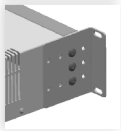
Figure 2
Input Connections

There are eight INPUT PORTS for PLUG-IN MODULES. Select the appropriate modules for each application. Plug the modules into the INPUT PORTS. Slide them between the card-edge guide rails and secure them with the provided screws as shown in Figure 3. Ensure screws are sufficiently tightened for proper grounding. For connection details, refer to the individual PLUG-IN MODULE Instruction Guide.
CAUTION: Plug-in Modules should not be inserted or removed while the mixer/amplifier is turned on. Cover unoccupied INPUT PORTS with provided blank panels and secure with screws.
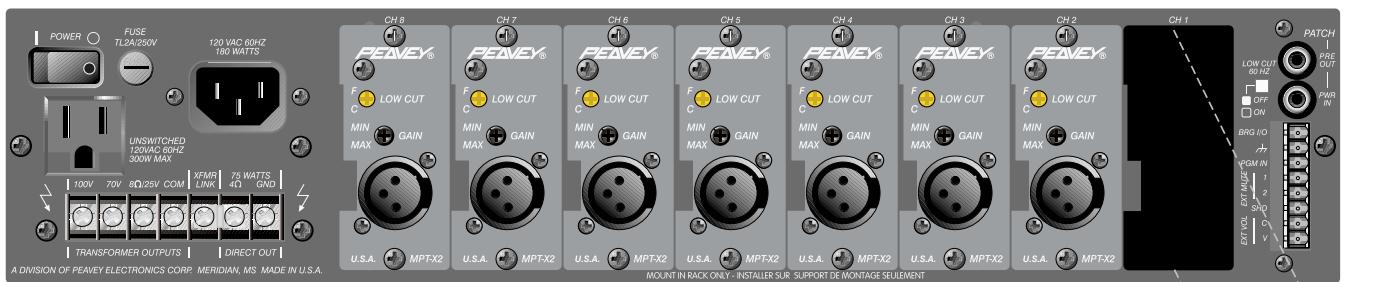
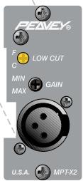
Figure 3
Loudspeaker Output Connections
MMA81502 (120V)
The loudspeaker outputs of the mixer/amplifier are 4 Ohms, 8 Ohms, 25V and 70V . Connect the loudspeaker system to any ONE of these outputs. Class 2 wiring may be used.
There are two types of output: 4 Ohm Direct Output;
8 Ohm, 25V, and 70V via Output Transformer
The method of connection differs in each case. Refer to Figure 4. If using the transformer isolated outputs be sure that the Low Cut switch is ON.
Note: Impedance values shown in Figure 4 indicate total loudspeaker system (load) impedance.
MMA 81502 (120V) Direct Output
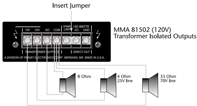
Figure 4
The loudspeaker outputs of the mixer/amplifier are 4 Ohms, 8 Ohms, 70V and 100V. Connect the loudspeaker system to any ONE of these outputs. Class 2 wiring may be used.
There are two types of output: 4 Ohm Direct Output; 8 Ohm, 7oV, and 100V via Output Transformer
The method of connection differs in each case. Refer to Figure 5. If using the transformer isolated outputs be sure that the Low Cut switch is ON.
Note: Impedance values shown in Figure 5 indicate total loudspeaker system (load) impedance.
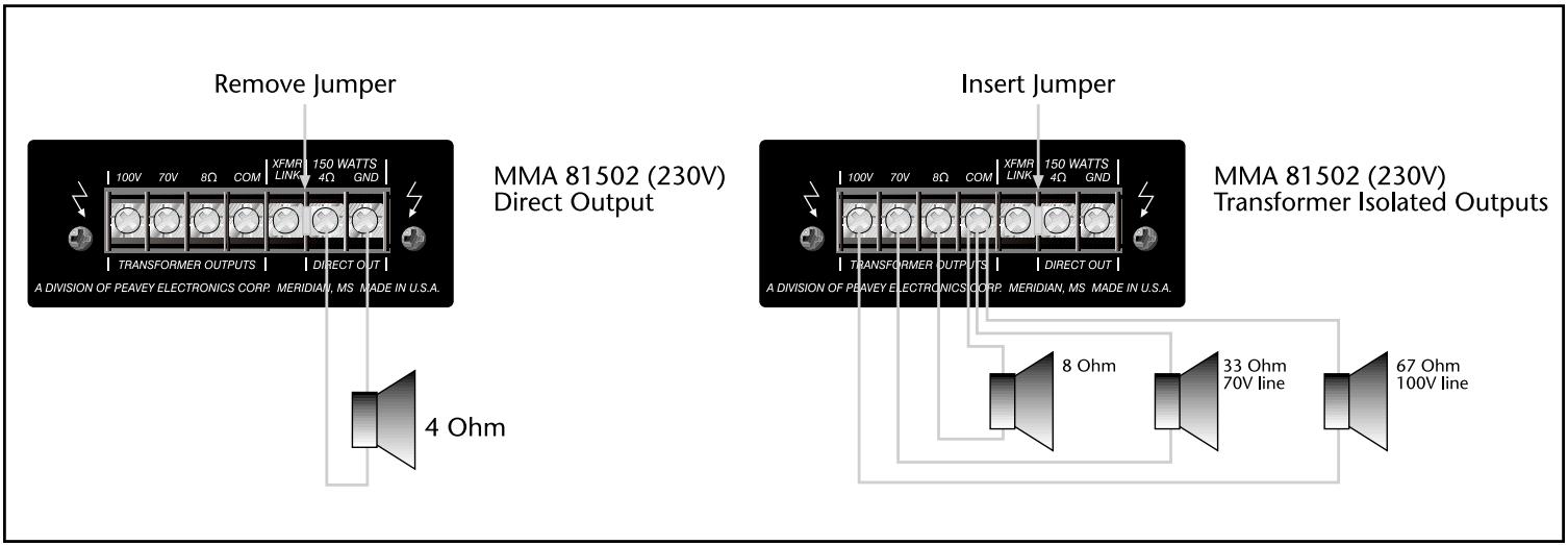
Figure 5
MMA8752 (120/230V)
The loudspeaker outputs of the mixer/amplifier are 4 Ohms, 8 Ohms/25V, 70V and 100V. Connect the loudspeaker system to any ONE of these outputs. Class 2 wiring may be used.
There are two types of output: 4 Ohm Direct Output; 8 Ohm/25V, 70V, and 100V via Output Transformer
The method of connection differs in each case. Refer to Figure 6. If using the transformer isolated outputs be sure that the Low Cut switch is ON.
Note: Impedance values shown in Figure 6 indicate total loudspeaker system (load) impedance.
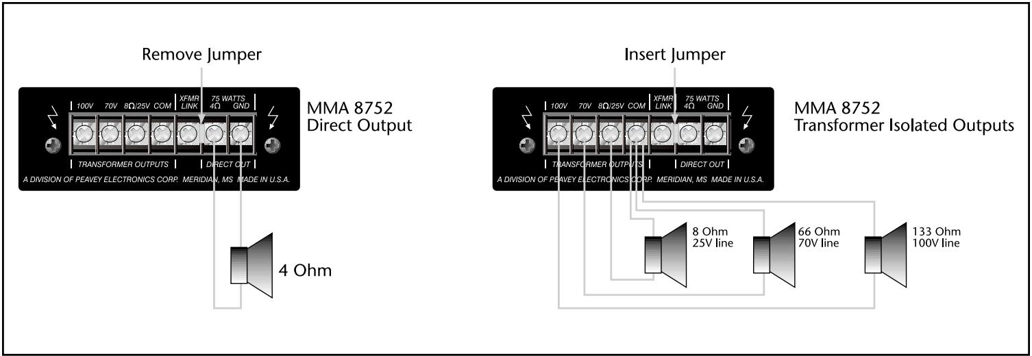
Figure 6
The loudspeaker outputs of the mixer/amplifier are 4 Ohms, 8 Ohms, 70V and 100V. Connect the loudspeaker system to any ONE of these outputs. Class 2 wiring may be used.
There are two types of output: 4 Ohm Direct Output; 8 Ohm, 7oV, and 100V via Output Transformer
The method of connection differs in each case. Refer to Figure 7. If using the transformer isolated outputs be sure that the Low Cut switch is ON.
Note: Impedance values shown in Figure 7 indicate total loudspeaker system (load) impedance.
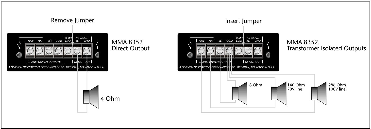
Figure 7
±0.5 dB, 20 Hz to 20 kHz, Direct Out
±1.0 dB, 50 Hz to 20 kHz, Transformer Out
Preamplifier:
±1.0 dB, 20 Hz to 20 kHz
THD:
Power Amplifier: 0.05% (1kHz)
Preamplifier: 0.10% with nominal gain settings
Power Bandwidth:
Direct Out: 10 Hz to 70 kHz
Transformer Out: 30 Hz to 40 kHz
Signal/ Noise:
(22 Hz-22 kHz) typical
All controls CCW: 100 dB
All controls nom: 95 dB
Master Level Max: 77 dB
Outputs:
Direct Out: 4 Ohms
Transformer Isolated: 8 Ohms, 25V, 70 V
(MMA81502, 120V only)
8 Ohms, 70 V, 100 V (MMA81502, 230V only)
8 Ohms/25V, 70 V, 100 V (MMA8752)
8 Ohms, 70 V, 100 V (MMA8352)
Pre Out: 1 V nom; +21 dBu max at 100 Ohms
Bridge In/Out: 100 mV at 3.3k Ohms
Input Sensitivity:
Bridge In/Out: 100 mV at 3.3k Ohms
Low EQ: ±10 dB at 100 Hz
High EQ: ±10 dB at 10 kHz
Front Panel Features:
Channel 1-8 Level Controls
Program Input Level Control
High EQ Control
Low EQ Control
EQ Bypass Switch
Master Level Control
Input Channel Signal Level Indicators (Signal
Presence: green; Signal Peak: red)
Mute Bus Status Indicators
Power Amplifier Signal Presence Indicator
SPSTM Indicator
Power On Indicator
Rear Panel Features:
Preamp Output
Power Amp Input
Program Input
Bridge In/Out
External Mute Terminals
External Volume Control
Plug-in Module Ports 1-8
Loudspeaker Output Terminals
AC convenience outlet (120V units only)
Power Switch
Fuse
IEC Power Connector
Muting:
MMA input module with muting capability overrides the Program Input on Mute 1 bus
Mute 1 and Mute 2 bus activation with switch
contact closure via screw terminals
Power Requirements:
MMA81502 (120V): 300 Watts, 120 Vac, 60 Hz
MMA81502 (230V): 300 Watts, 230 Vac, 50/60 Hz
MMA8752 (120V): 180 Watts, 120 Vac, 60 Hz
MMA8752 (230V): 180 Watts, 230 Vac, 50/60 Hz
MMA8352 (120V): 100 Watts, 120 Vac, 60 Hz
Dimensions:
19.00" (W) X 13.25" (D) X 3.45" (H) with rack ears and without feet (483 mm X 337 mm X 88 mm)
17.00" (W) X 13.25" (D) X 4.00" (H) without rack ears and with feet (432 mm X 337 mm X 102 mm)
Weight:
MMA81502: 28.3 lbs. (12.9 kg)
MMA8752: 25.0 lbs. (11.4 kg)
MMA8352: 21.1 lbs. (9.6 kg)
Color:
Black
DEUTSCH
Description:
MMA™ Mixer/Power Amplifier Systems
External Volume Control connection limiting front panel master volume control range
±1.0 dB, 50 Hz to 20 kHz, Transformer Out
Preamplifier:
±1.0 dB, 20 Hz to 20 kHz
THD:
Power Amplifier: 0.05% (1kHz)
Preamplifier: 0.10% with nominal gain settings
Power Bandwidth:
Direct Out: 10 Hz to 70 kHz
Transformer Out: 30 Hz to 40 kHz
Signal/ Noise:
(22 Hz-22 kHz) typical
All controls CCW: 100 dB
All controls nom: 95 dB
Master Level Max: 77 dB
Outputs:
Direct Out: 4 Ohms
Transformer Isolated: 8 Ohms, 25V, 70 V
(MMA81502, 120V only)
8 Ohms, 70 V, 100 V (MMA81502, 230V only)
8 Ohms/25V, 70 V, 100 V (MMA8752)
8 Ohms, 70 V, 100 V (MMA8352)
Pre Out: 1 V nom; +21 dBu max at 100 Ohms
Bridge In/Out: 100 mV at 3.3k Ohms
Input Sensitivity:
Bridge In/Out: 100 mV at 3.3k Ohms
Low EQ: ±10 dB at 100 Hz
High EQ: ±10 dB at 10 kHz
Front Panel Features:
Channel 1-8 Level Controls
Program Input Level Control
High EQ Control
Low EQ Control
EQ Bypass Switch
Master Level Control
Input Channel Signal Level Indicators (Signal
Presence: green; Signal Peak: red)
Mute Bus Status Indicators
Power Amplifier Signal Presence Indicator
SPS™ Indicator
Power On Indicator
Rear Panel Features:
Preamp Output
Power Amp Input
Program Input
Bridge In/Out
External Mute Terminals
External Volume Control
Plug-in Module Ports 1-8
Loudspeaker Output Terminals
AC convenience outlet (120V units only)
Power Switch
Fuse
IEC Power Connector
Muting:
MMA input module with muting capability overrides the Program Input on Mute 1 bus
Mute 1 and Mute 2 bus activation with switch
contact closure via screw terminals
Power Requirements:
MMA81502 (120V): 300 Watts, 120 Vac, 60 Hz
MMA81502 (230V): 300 Watts, 230 Vac, 50/60 Hz
MMA8752 (120V): 180 Watts, 120 Vac, 60 Hz
MMA8752 (230V): 180 Watts, 230 Vac, 50/60 Hz
MMA8352 (120V): 100 Watts, 120 Vac, 60 Hz
Dimensions:
19.00" (W) X 13.25" (D) X 3.45" (H) with rack ears and without feet (483 mm X 337 mm X 88 mm)
17.00" (W) X 13.25" (D) X 4.00" (H) without rack ears and with feet (432 mm X 337 mm X 102 mm)
Weight:
MMA81502: 28.3 lbs. (12.9 kg)
MMA8752: 25.0 lbs. (11.4 kg)
MMA8352: 21.1 lbs. (9.6 kg)
Color:
Black
FRANÇAIS
Description:
MMA™ Mixer/Power Amplifier Systems
4. Input Channel Level Controls
5. Input Channel Signal Status Indicators
7. Low EQ Control (Bass)
8. High EQ Control (Treble)
15. AC Outlet (Unswitched)
External Volume Control connection limiting front panel master volume control range
Installing Rack-mount Ears
Loudspeaker Output Connections
MMA81502 (120V)
8 Ohm, 25V, and 70V via Output Transformer
8 Ohm, 25V, and 70V via Output Transformer
MMA 81502 (230V) Direct Output
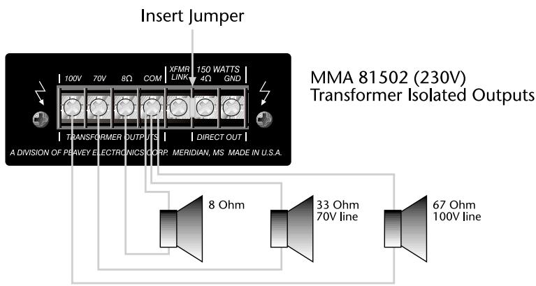
Figure 5
MMA8752 (120/230V)
8 Ohm, 25V, and 70V via Output Transformer
MMA™ Mixer/Power Amplifier Systems
External Volume Control connection limiting front panel master volume control range
Insert Jumper
MMA 81502 (120V)
Transformer Isolated Outputs
Figure 4
Remove Jumper
MMA 8352 Direct Output
Insert Jumper
Figure 7
Specifications
Rated Output Power:
MMA81502: 150 W
MMA8752: 75 W
MMA8352: 35 W
Output Regulation:
Direct Out: ± 0.5dB
Transformer Out: ± 1.0dB
Frequency Response:
Power Amplifier:
±0.5 dB, 20 Hz to 20 kHz, Direct Out
±1.0 dB, 50 Hz to 20 kHz, Transformer Out
Preamplifier:
±1.0 dB, 20 Hz to 20 kHz
THD:
Power Amplifier: 0.05% (1kHz)
Preamplifier: 0.10% with nominal gain settings
Power Bandwidth:
Direct Out: 10 Hz to 70 kHz
Transformer Out: 30 Hz to 40 kHz
Signal/ Noise:
(22 Hz-22 kHz) typical
All controls CCW: 100 dB
All controls nom: 95 dB
Master Level Max: 77 dB
Outputs:
Direct Out: 4 Ohms
Transformer Isolated: 8 Ohms, 25V, 70 V
(MMA81502, 120V only)
8 Ohms, 70 V, 100 V (MMA81502, 230V only)
8 Ohms/25V, 70 V, 100 V (MMA8752)
8 Ohms, 70 V, 100 V (MMA8352)
Pre Out: 1 V nom; +21 dBu max at 100 Ohms
Bridge In/Out: 100 mV at 3.3k Ohms
Input Sensitivity:
Bridge In/Out: 100 mV at 3.3k Ohms
Low EQ: ±10 dB at 100 Hz
High EQ: ±10 dB at 10 kHz
Front Panel Features:
Channel 1-8 Level Controls
Program Input Level Control
High EQ Control
Low EQ Control
EQ Bypass Switch
Master Level Control
Input Channel Signal Level Indicators (Signal
Presence: green; Signal Peak: red)
Mute Bus Status Indicators
Power Amplifier Signal Presence Indicator
SPS™ Indicator
Power On Indicator
Rear Panel Features:
Preamp Output
Power Amp Input
Program Input
Bridge In/Out
External Mute Terminals
External Volume Control
Plug-in Module Ports 1-8
Loudspeaker Output Terminals
AC convenience outlet (120V units only)
Power Switch
Fuse
IEC Power Connector
Muting:
MMA input module with muting capability overrides the Program Input on Mute 1 bus
Mute 1 and Mute 2 bus activation with switch
contact closure via screw terminals
Power Requirements:
MMA81502 (120V): 300 Watts, 120 Vac, 60 Hz
MMA81502 (230V): 300 Watts, 230 Vac, 50/60 Hz
MMA8752 (120V): 180 Watts, 120 Vac, 60 Hz
MMA8752 (230V): 180 Watts, 230 Vac, 50/60 Hz
MMA8352 (120V): 100 Watts, 120 Vac, 60 Hz
Dimensions:
19.00" (W) X 13.25" (D) X 3.45" (H) with rack ears and without feet (483 mm X 337 mm X 88 mm)
17.00" (W) X 13.25" (D) X 4.00" (H) without rack ears and with feet (432 mm X 337 mm X 102 mm)
Weight:
MMA81502: 28.3 lbs. (12.9 kg)
MMA8752: 25.0 lbs. (11.4 kg)
MMA8352: 21.1 lbs. (9.6 kg)
Color:
Black
NOTES:
Architectural Acoustics®
PEAVEY ELECTRONICS CORPORATION LIMITED WARRANTY
Effective Date: July 1, 1998
What This Warranty Covers
Your Peavey Warranty covers defects in material and workmanship in Peavey products purchased and serviced in the U.S.A. and Canada.
What This Warranty Does Not Cover
The Warranty does not cover: (1) damage caused by accident, misuse, abuse, improper installation or operation, rental, product modification or neglect; (2) damage occurring during shipment; (3) damage caused by repair or service performed by persons not authorized by Peavey; (4) products on which the serial number has been altered, defaced or removed; (5) products not purchased from an Authorized Peavey Dealer.
Who This Warranty Protects
This Warranty protects only the original retail purchaser of the product.
How Long This Warranty Lasts
The Warranty begins on the date of purchase by the original retail purchaser. The duration of the Warranty is as follows:
| Product Category | Duration |
| MediaMatrix®DPU (Excluding Frames), Cinema Processors, Power Amplifiers, Pre-Amplifiers, Mixers, Electronic Crossovers and Equalizers | 5 years |
| Loudspeakers | 5 years |
| Microphones | 2 years |
| Frames | 1 year |
| Speaker Components (incl. speakers, baskets, drivers, diaphragm replacement kits and passive crossovers) and all Accessories | 1 year |
What Peavey Will Do
We will repair or replace (at Peavey's discretion) products covered by warranty at no charge for labor or materials. If the product or component must be shipped to Peavey for warranty service, the consumer must pay initial shipping charges. If the repairs are covered by warranty, Peavey will pay the return shipping charges.
How To Get Warranty Service
(1) Take the defective item and your sales receipt or other proof of date of purchase to your Authorized Peavey Dealer or Authorized Peavey Service Center.
OR
(2) Ship the defective item, prepaid, to Peavey Electronics Corporation, International Service Center, 412 Highway 11 & 80 East, Meridian, MS 39301 or Peavey Canada Ltd., 95 Shields Court, Markham, Ontario, Canada L3R 9T5. Include a detailed description of the problem, together with a copy of your sales receipt or other proof of date of purchase as evidence of warranty coverage. Also provide a complete return address.
OR
(3) All MediaMatrix® Frames needing repair, should be shipped prepaid to Peavey Electronics Corporation, International Service Center, 412 Highway 11 & 80 East, Meridian, MS 39301
Limitation of Implied Warranties
ANY IMPLIED WARRANTYES, INCLUDING WARRANTYES OF MERCHANTABILITY AND FITNESS FOR A PARTICULAR PURPOSE, ARE LIMITED IN DURATION TO THE LENGTH OF THIS WARRANTY.
Some states do not allow limitations on how long an implied warranty lasts, so the above limitation may not apply to you.
Exclusions of Damages
PEAVEY'S LIABILITY FOR ANY DEFECTIVE PRODUCT IS LIMITED TO THE REPAIR OR REPLACEMENT OF THE PRODUCT, AT PEAVEY'S OPTION. IF WE ELECT TO REPLACE THE PRODUCT, THE REPLACEMENT MAY BE A RECONDITIONED UNIT. PEAVEY SHALL NOT BE LIABLE FOR DAMAGES BASED ON INCONVENIENCE, LOSS OF USE, LOST PROFITS, LOST SAVINGS, DAMAGE TO ANY OTHER EQUIPMENT OR OTHER ITEMS AT THE SITE OF USE, OR ANY OTHER DAMAGES WHETHER INCIDENTAL, CONSEQUENTAL OR OTHERWISE, EVEN IF PEAVEY HAS BEEN ADVISED OF THE POSSIBILITY OF SUCH DAMAGES.
Some states do not allow the exclusion or limitation of incidental or consequential damages, so the above limitation or exclusion may not apply to you.
This Warranty gives you specific legal rights, and you may also have other rights which vary from state to state.
If you have any questions about this warranty or service received or if you need assistance in locating an Authorized Service Center, please contact the Peavey International Service Center at (601) 483-5365 / Peavey Canada Ltd. at (905) 475-2578.
Features and specifications subject to change without notice.
- SAVE THESE INSTRUCTIONS!
- ENGLISH
- Description:
- MMA™ Mixer/Power Amplifier Systems
- Features:
- Applications
- Front Panel
- Power Indicator
- Signal Level Indicator
- SPS™ Indicator
- Input Channel Level Controls
- Input Channel Signal Status Indicators
- Program Input Level Control
- Low EQ Control (Bass)
- High EQ Control (Treble)
- EQ Bypass Switch
- Mute Bus Indicators
- Master Level Control
- Rear Panel
- AC Power Receptacle
- Power Switch
- Fuse
- AC Outlet (Unswitched)
- Outputs
- Module Input Ports 1-6
- Module Input Ports 7-8
- Low cut switch
- Preamplifier Out
- Power Amplifier Input
- Bridge In/Out
- Program Input
- Ext Mute 1/2
- External Volume Control
- Potentiometer
- Installing Rack-mount Ears
- Input Connections
- Loudspeaker Output Connections
- MMA81502 (120V)
- MMA8752 (120/230V)
- THD:
- Power Bandwidth:
- Signal/ Noise:
- Outputs:
- Input Sensitivity:
- Front Panel Features:
- Rear Panel Features:
- Muting:
- Power Requirements:
- Dimensions:
- Weight:
- Color:
- DEUTSCH
- FRANÇAIS
- Specifications
- Rated Output Power:
- Output Regulation:
- Frequency Response:
- Architectural Acoustics®
- PEAVEY ELECTRONICS CORPORATION LIMITED WARRANTY
- What This Warranty Covers
- What This Warranty Does Not Cover
- Who This Warranty Protects
- How Long This Warranty Lasts
- What Peavey Will Do
- How To Get Warranty Service
- Limitation of Implied Warranties
- Exclusions of Damages
Brand : PEAVEY
Model : MMA 8752
Category : Audio Amplifier