
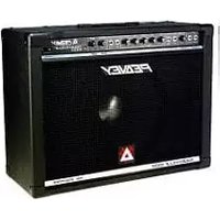
PVi 4B - Audio Amplifier PEAVEY - Free user manual and instructions
Find the device manual for free PVi 4B PEAVEY in PDF.

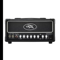
| Product type | Audio amplifier |
| Brand | Peavey |
| Model | PVi 4B |
| Power supply | Mains with ground plug |
| Power cord | Provided, connection to a grounded outlet |
| Cleaning | Dry cloth only |
| Rack mounting | Yes, rear support brackets required |
| Protection | Do not expose to moisture or rain |
| Maintenance | Refer to a Peavey authorized repair technician |
| Safety | Do not open the chassis, risk of electric shock |
| Usage | Indoor use only |
| Switch | On/Off on the panel |
| Features | Audio amplification with inputs and outputs |
Frequently Asked Questions - PVi 4B PEAVEY
User questions about PVi 4B PEAVEY
0 question about this device. Answer the ones you know or ask your own.
Ask a new question about this device
Download the instructions for your Audio Amplifier in PDF format for free! Find your manual PVi 4B - PEAVEY and take your electronic device back in hand. On this page are published all the documents necessary for the use of your device. PVi 4B by PEAVEY.
USER MANUAL PVi 4B PEAVEY
Intended to alert the user to the presence of uninsulated "dangerous voltage" within the product's enclosure that may be of sufficient magnitude to constitute a risk of electric shock to persons.
Intended to alert the user of the presence of important operating and maintenance (servicing) instructions in the literature accompanying the product.
CAUTION: Risk of electrical shock — DO NOT OPEN!
CAUTION: To reduce the risk of electric shock, do not remove cover. No user serviceable parts inside. Refer servicing to qualified service personnel.
WARNING: To prevent electrical shock or fire hazard, this apparatus should not be exposed to rain or moisture, and objects filled with liquids, such as vases, should not be placed on this apparatus. Before using this apparatus, read the operating guide for further warnings.

Protective earthing terminal. The apparatus should be connected to a mains socket outlet with a protective earthing connection.

IMPORTANT SAFETY INSTRUCTIONS
WARNING: When using electrical products, basic cautions should always be followed, including the following:
- Read these instructions.
- Keep these instructions.
- Heed all warnings.
- Follow all instructions.
- Do not use this apparatus near water.
- Clean only with a dry cloth.
- Do not block any of the ventilation openings. Install in accordance with manufacturer's instructions.
- Do not install near any heat sources such as radiators, heat registers, stoves or other apparatus (including amplifiers) that produce heat.
- Do not defeat the safety purpose of the polarized or grounding-type plug. A polarized plug has two blades with one wider than the other. A grounding type plug has two blades and a third grounding plug. The wide blade or third prong is provided for your safety. If the provided plug does not fit into your outlet, consult an electrician for replacement of the obsolete outlet.
- Protect the power cord from being walked on or pinched, particularly at plugs, convenience receptacles, and the point they exit from the apparatus.
- Only use attachments/accessories provided by the manufacturer.
- Use only with a cart, stand, tripod, bracket, or table specified by the manufacturer, or sold with the apparatus. When a cart is used, use caution when moving the cart/apparatus combination to avoid injury from tip-over.
- Unplug this apparatus during lightning storms or when unused for long periods of time.
- Refer all servicing to qualified service personnel. Servicing is required when the apparatus has been damaged in any way, such as power-supply cord or plug is damaged, liquid has been spilled or objects have fallen into the apparatus, the apparatus has been exposed to rain or moisture, does not operate normally, or has been dropped.
- Never break off the ground pin. Write for our free booklet "Shock Hazard and Grounding." Connect only to a power supply of the type marked on the unit adjacent to the power supply cord.
- If this product is to be mounted in an equipment rack, rear support should be provided.
- Note for UK only: If the colors of the wires in the mains lead of this unit do not correspond with the terminals in your plug, proceed as follows: a) The wire that is colored green and yellow must be connected to the terminal that is marked by the letter E, the earth symbol, colored green or colored green and yellow. b) The wire that is colored blue must be connected to the terminal that is marked with the letter N or the color black. c) The wire that is colored brown must be connected to the terminal that is marked with the letter L or the color red.
- This electrical apparatus should not be exposed to dripping or splashing and care should be taken not to place objects containing liquids, such as vases, upon the apparatus.
- The on/off switch in this unit does not break both sides of the primary mains. Hazardous energy can be present inside the chassis when the on/off switch is in the off position. The mains plug or appliance coupler is used as the disconnect device, the disconnect device shall remain readily operable.
- Exposure to extremely high noise levels may cause a permanent hearing loss. Individuals vary considerably in susceptibility to noise-induced hearing loss, but nearly everyone will lose some hearing if exposed to sufficiently intense noise for a sufficient time. The U.S. Government's Occupational Safety and Health Administration (OSHA) has specified the following permissible noise level exposures:
Duration Per Day In Hours Sound Level dBA, Slow Response
| 8 | 90 | |
| 6 | 92 | |
| 4 | 95 | |
| 3 | 97 | |
| 2 | 100 | |
| 1 1/2 | 102 | |
| 1 | 105 | |
| 1/2 | ||
| 1/4 or less |
According to OSHA, any exposure in excess of the above permissible limits could result in some hearing loss. Earplugs or protectors to the ear canals or over the ears must be worn when operating this amplification system in order to prevent a permanent hearing loss, if exposure is in excess of the limits as set forth above. To ensure against potentially dangerous exposure to high sound pressure levels, it is recommended that all persons exposed to equipment capable of producing high sound pressure levels such as this amplification system be protected by hearing protectors while this unit is in operation.
SAVE THESE INSTRUCTIONS!
a) The wire that is colored green and yellow must be connected to the terminal that is marked by the letter E, the earth symbol, colored green or colored green and yellow.
b) The wire that is colored blue must be connected to the terminal that is marked with the letter N or the color black.
c) The wire that is colored brown must be connected to the terminal that is marked with the letter L or the color red.
FCC Compliancy Statement
This device complies with part 15 of the FCC Rules. Operation is subject to the following two conditions: (1) This device may not cause harmful interference, and (2) this device must accept any interference received, including interference that may cause undesired operation.
Warning: Changes or modifications to the equipment not approved by Peavey Electronics Corp. can void the user's authority to use the equipment.

Peavey Electronics Corporation • 5022 Hartley Peavey Drive • Meridian, MS • 39305
(601) 483-5365 • FAX (601) 486-1278 • www.peavey.com • ©2012

Logo referenced in Directive 2002/96/EC Annex IV(OJ(L)37/38,13.02.03 and defined in EN 50419: 2005
The bar is the symbol for marking of new waste and is applied only to equipment manufactured after 13 August 2005
Correct Disposal of this product. This marking indicates that this product should not be disposed with other house hold wastes throughout the EU. To prevent possible harm to the environment or human health from uncontrolled waste disposal, recycle it responsibly to promote the sustainable reuse of material resources. To return your used device, please use the return and collection systems, or contact the retailer where the product was purchased. They can take this product for environmental safe recycling.

This input is for balanced, low impedance microphones. It will automatically provide phantom power (15V) for condenser mics or active direct boxes. This has an input impedance of 1k ohm. The connector is wired as: Pin 1=shield; Pin 2=positive hot; Pin 3=negative cold.
(2) 1/4" LINE/HIGH IMPEDANCE INPUT
This input may be used as either a high impedance microphone input or a line-level device such as a cassette player, CD player, return or radio. This will also allow connection from an electric guitar, bass or keyboard. It is a two-conductor input with an impedance of 10k ohms.
Features
(3) LEVEL CONTROL
The level control for each channel sends the signal to the master mix bus. Typical operation is between 4 and 8 (dependent upon the devices). Please remember that this acts like a preamp, so if you are using a device that has a volume output control (i.e.: a tape or CD player) you will need to do some level matching by adjusting the level controls on each unit.
(4) TONE CONTROL
This is used to adjust the overall tone of the individual inputs. Since it is a cut or boost control (+/-15 dB), it will add or diminish presence frequencies in the sound.
(5) REVERB CONTROL
This is used as a send control to the reverb bus. It controls the amount of reverberation added to the input signals.
(6) MASTER LEVEL
This controls the overall volume level of the entire amplifier. Typical operation is between 4 and 8.
(7) MASTER REVERB
This controls the level of Reverb that is added back to the mix.
(8) TAPE VOLUME
This controls the level of the playback inputs (RCA jacks on rear panel).
(9) MASTER EQ
These are used to adjust the overall EQ of the master mix. Since these cover three frequency bands (+/-15 dB), they will add or diminish the low, mid or high frequencies in the sound.
(10) POWER
This switches the unit on or off. When the unit is powered up, a blue LED will illuminate.
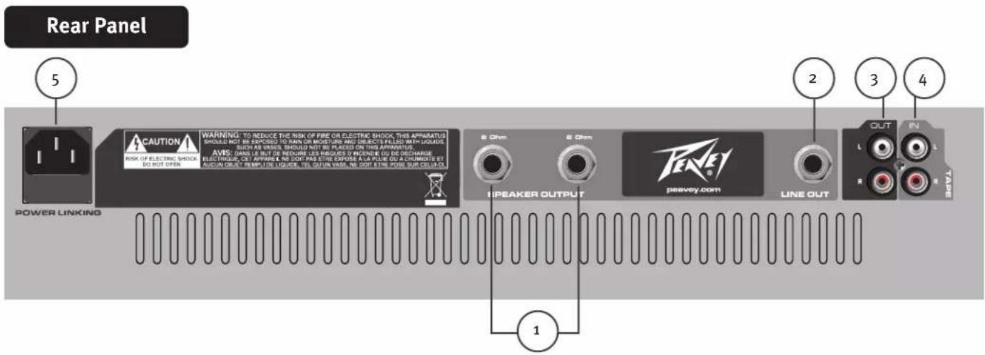

(1) SPEAKER OUTPUTS
These are two-conductor 1/4" speaker outputs. Each one is rated at 8 ohms minimum impedance. Total minimum load for the amplifier is 4 ohms. You may connect either one 4-ohm, one 8-ohm or two 8-ohm speakers. Do not operate below rated minimum impedance. Be sure to use speaker cables and not instrument cables to connect to the speakers.
(2) LINE OUT
This is a 1/4" two-conductor line output. It is used to connect the PVi™4B to an additional power amp or to send a submix to a larger P.A. system. This line-level signal is a mirror image of the main outputs.
(3) TAPE OUT (L/R)
These RCA output jacks are primarily intended for connecting a tape deck, MP3, or other device for the purpose of recording from the mixer. Both channels are summed into mono for compatibility. The signals are taken pre-master section, meaning that they are without reverb or the master tone section, and do not include the Tape-In signal. If you wish to record with the reverb and Tape In signals, use the 1/4" line output (2) with the proper cable.
(4) TAPE IN (L/R)
These RCA jacks are for connecting a cassette deck, CD player or other line-level source.
(5) POWER LINKING CONNECTOR
This is a standard IEC cable connector for use with standard voltages from AC wall outlets. It is grounded and should never have the ground pin removed for any reason. The IEC connector contains an internal fuse holder. The fuse rating is 2.5 amps slow-blow.

WARNING
THE ON/OFF SWITCH IN THIS APPARATUS DOES NOT BREAK BOTH SIDES OF THE MAINS. HAZARDOUS ENERGY MAY BE PRESENT INSIDE THE ENCLOSURE WHEN THE POWER SWITCH IS IN THE OFF POSITION.
PVi™4B
SPECIFICATIONS
Output Power:
100 watts / 4 ohms
75 watts / 8 ohms
Aux SEND Output:
-10 dBv nominal, 1k ohms
Tape REC Output:
-10 dBv nominal, 1k ohms
Input Impedance:
Low-Z Mic: 1k ohms
High-Z Line: 10k ohms
Tape Input: 10k ohms
Input Channel Equalization:
+/- 15 dB @ 5 kHz
Master Equalization:
Low: +/ - 15 @ 60 Hz
Mid: +/-15 @ 1 kHz
High: +/- 15 @ 10 kHz
Protection Circuit:
Power on Mute delay time: 2 seconds
Power Consumption:
200 watts
Dimensions (HxWxD):
5 3/4"×19 7/16"×9 1/2"
14.6 cm × 49.4 cm × 24.1 cm
Weight:
18 lbs. (8.2 kg)
ESPAÑOL
PVi™4B
Logo referenced in Directive 2002/96/EC Annex IV (OJ(L)37/38,13.02.03 and defined in EN 50419: 2005
The bar is the symbol for marking of new waste and
Is applied only to equipment manufactured after 13 August 2005

Features and specifications subject to change without notice.
Peavey Electronics Corporation • 5022 Hartley Peavey Drive • Meridian • MS • 39305
(601) 483-5365 • FAX (601) 486-1278 • www.peavey.com
EX 000038

- IMPORTANT SAFETY INSTRUCTIONS
- SAVE THESE INSTRUCTIONS!
- FCC Compliancy Statement
- 1/4" LINE/HIGH IMPEDANCE INPUT
- Features
- LEVEL CONTROL
- TONE CONTROL
- REVERB CONTROL
- MASTER LEVEL
- MASTER REVERB
- TAPE VOLUME
- MASTER EQ
- POWER
- SPEAKER OUTPUTS
- LINE OUT
- TAPE OUT (L/R)
- TAPE IN (L/R)
- POWER LINKING CONNECTOR
- WARNING
- PVi™4B
- SPECIFICATIONS
- ESPAÑOL
Brand : PEAVEY
Model : PVi 4B
Category : Audio Amplifier