5231 SP-A - Lawn mower SOLO - Free user manual and instructions
Find the device manual for free 5231 SP-A SOLO in PDF.
| Product type | Petrol lawn mower |
| Brand | SOLO |
| Model | 5231 SP-A |
| Intended use | Lawn mowing in private areas, on dry grass |
| Engine type | 4-stroke petrol engine |
| Starting | Manual (pull cord) or electric (optional) |
| Cutting height adjustment | Central or individual wheel, multiple notches |
| Cutting width | Approx. 53 cm (estimated) |
| Grass catcher | Yes, with level indicator |
| Mulching kit | Optional (mulching) |
| Side discharge | Optional |
| Wheel drive | Optional, with variable speed drive (Vario) |
| Safety devices | Safety bar, deflector flap |
| Maintenance | Cleaning after each use, sharpening/replacement of the blade, engine oil change, replacement of air filter and spark plug |
| Fuel | Regular unleaded petrol |
| Engine oil | Approx. 0.6 L, according to manufacturer's recommendations |
Frequently Asked Questions - 5231 SP-A SOLO
User questions about 5231 SP-A SOLO
0 question about this device. Answer the ones you know or ask your own.
Ask a new question about this device
Download the instructions for your Lawn mower in PDF format for free! Find your manual 5231 SP-A - SOLO and take your electronic device back in hand. On this page are published all the documents necessary for the use of your device. 5231 SP-A by SOLO.
USER MANUAL 5231 SP-A SOLO
text_image
D DK GB S NL N F FIN E EST P LV I LT SLO RUS HR UA SRB BG PL RO CZ GR SK MK H TRINFORMATION | MANUALS | SERVICE
BENZINRASENMÄHER
Betriebsanleitung


470 592_c I 10/2014

GB: Operating Instructions .....22
natural_image
Technical diagram showing a mechanical assembly with a bracket and housing, no visible text or symbols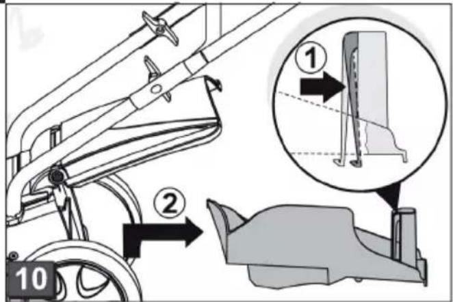
text_image
Technical diagram illustrating mechanical assembly steps with numbered annotations and magnified detail view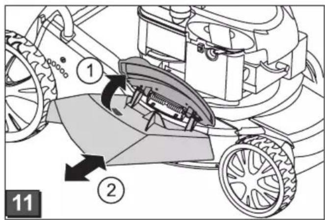
text_image
Diagram of a lawn mower showing labeled parts and motion arrows, likely illustrating mechanical or robotic movement.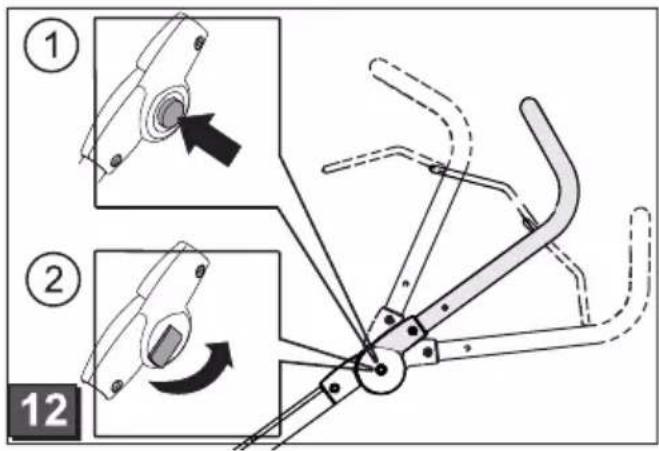
text_image
Technical diagram illustrating mechanical assembly steps with numbered instructions and component illustrations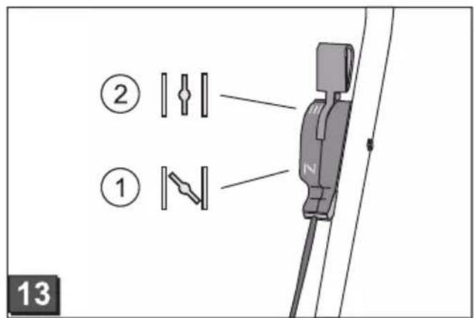
text_image
② ① 13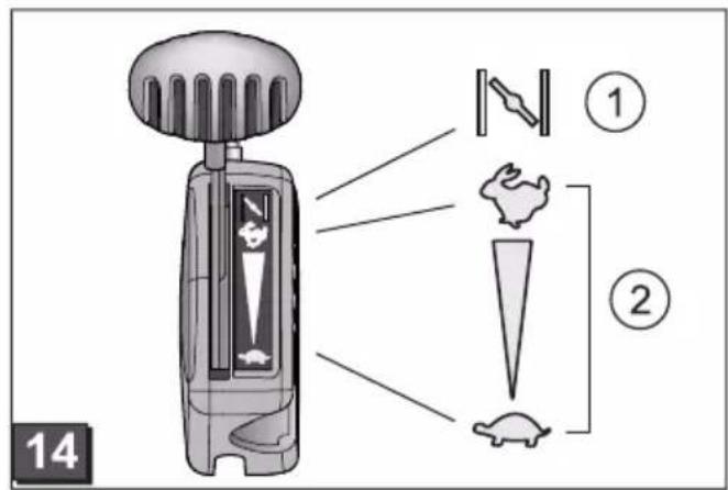
text_image
14 ① ②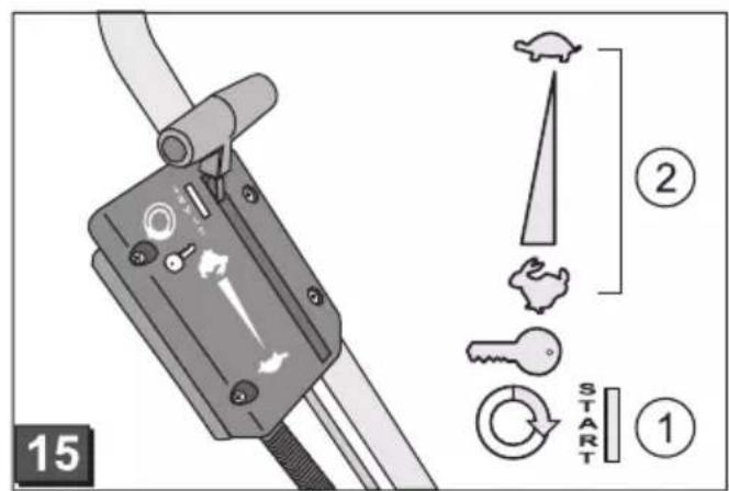
text_image
15 2 START 1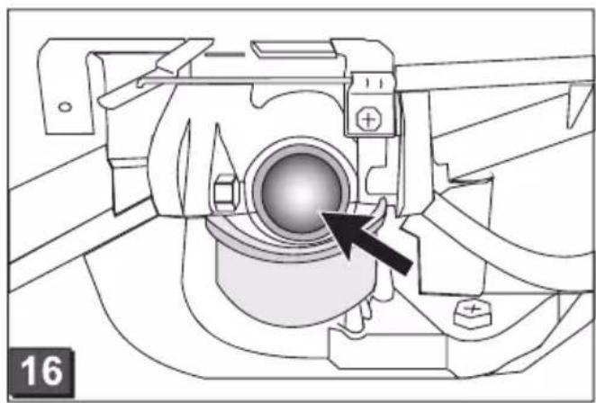
natural_image
Technical diagram of a mechanical assembly with a central component and directional arrow (no text or symbols)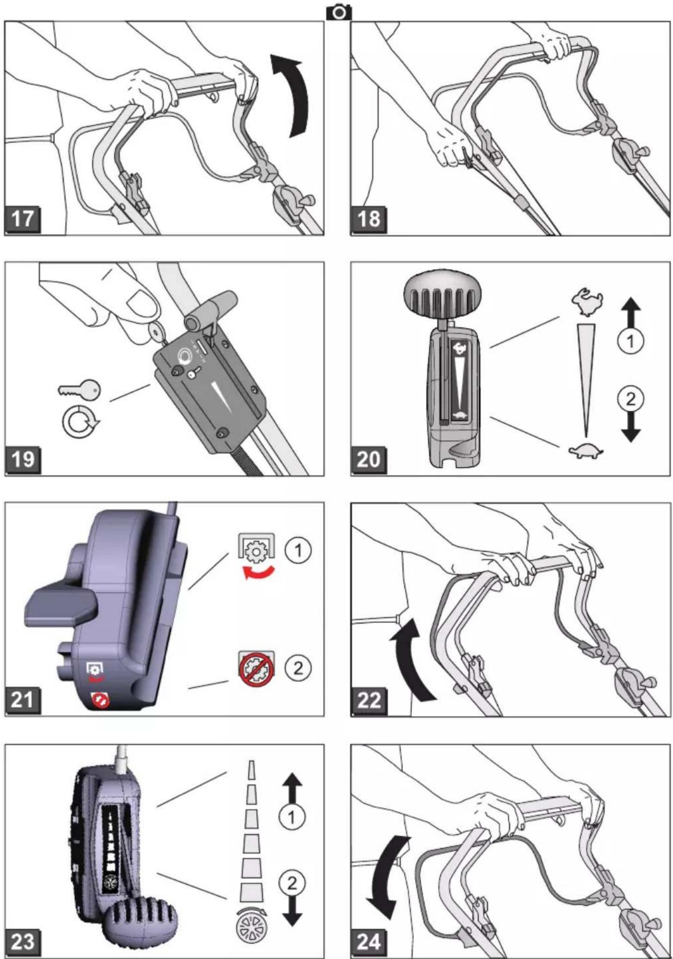
©
natural_image
Illustration of a person using a cable clamp device to lift a vehicle (no text or symbols present)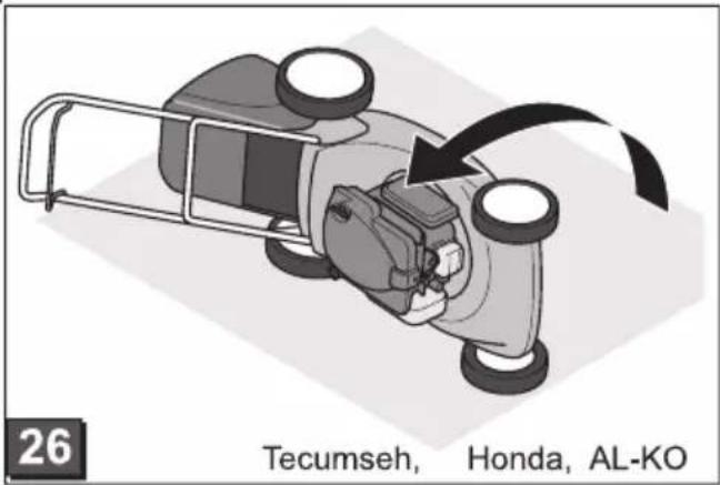
text_image
26 Tecumseh, Honda, AL-KO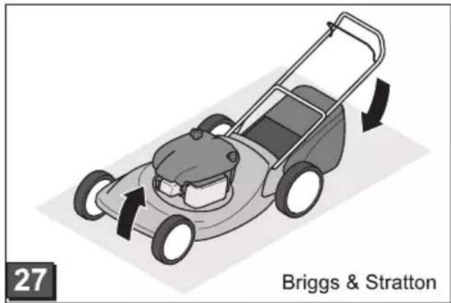
natural_image
Illustration of a lawn mower with directional arrows indicating motion (no text or symbols on the diagram itself)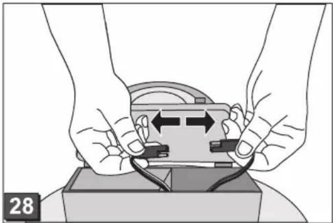
natural_image
Illustration of hands connecting wires to a device component (no text or symbols visible)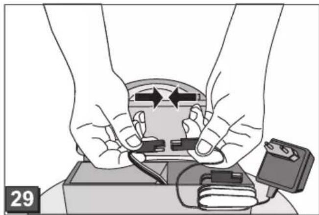
natural_image
Illustration of hands installing or adjusting a device with wires and components (no text or symbols visible)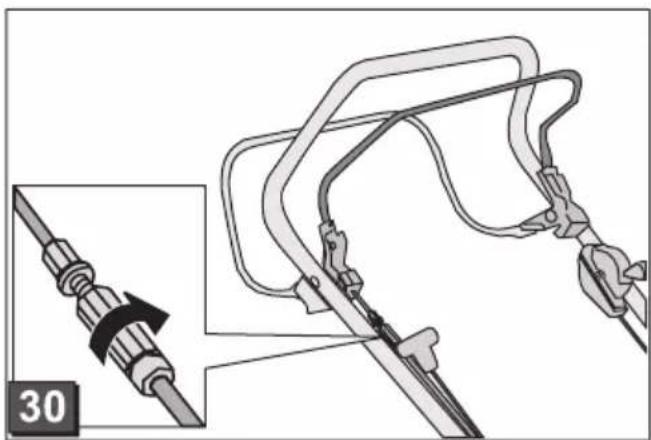
natural_image
Diagram of a mechanical device with a close-up view showing a cable being inserted into a bracket (no text or symbols present)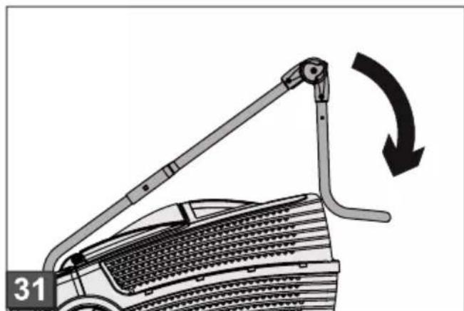
natural_image
Diagram of a car's lift mechanism with arrow indicating rotational motion (no text or symbols)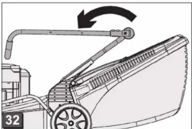
natural_image
Line drawing of a lawn mower with a handle and blade, showing mechanical components and motion direction (no text or symbols)Zu diesem Handbuch
text_image
Technical diagram of a lawn mower with numbered parts and exploded views, including front, side, and top views.- Read through these operating instructions before starting up the machine. This is a prerequisite for safe and trouble-free working.
■ You should save these instructions, and also pass them on to any subsequent users. - Observe the safety and warning signs on the machine.
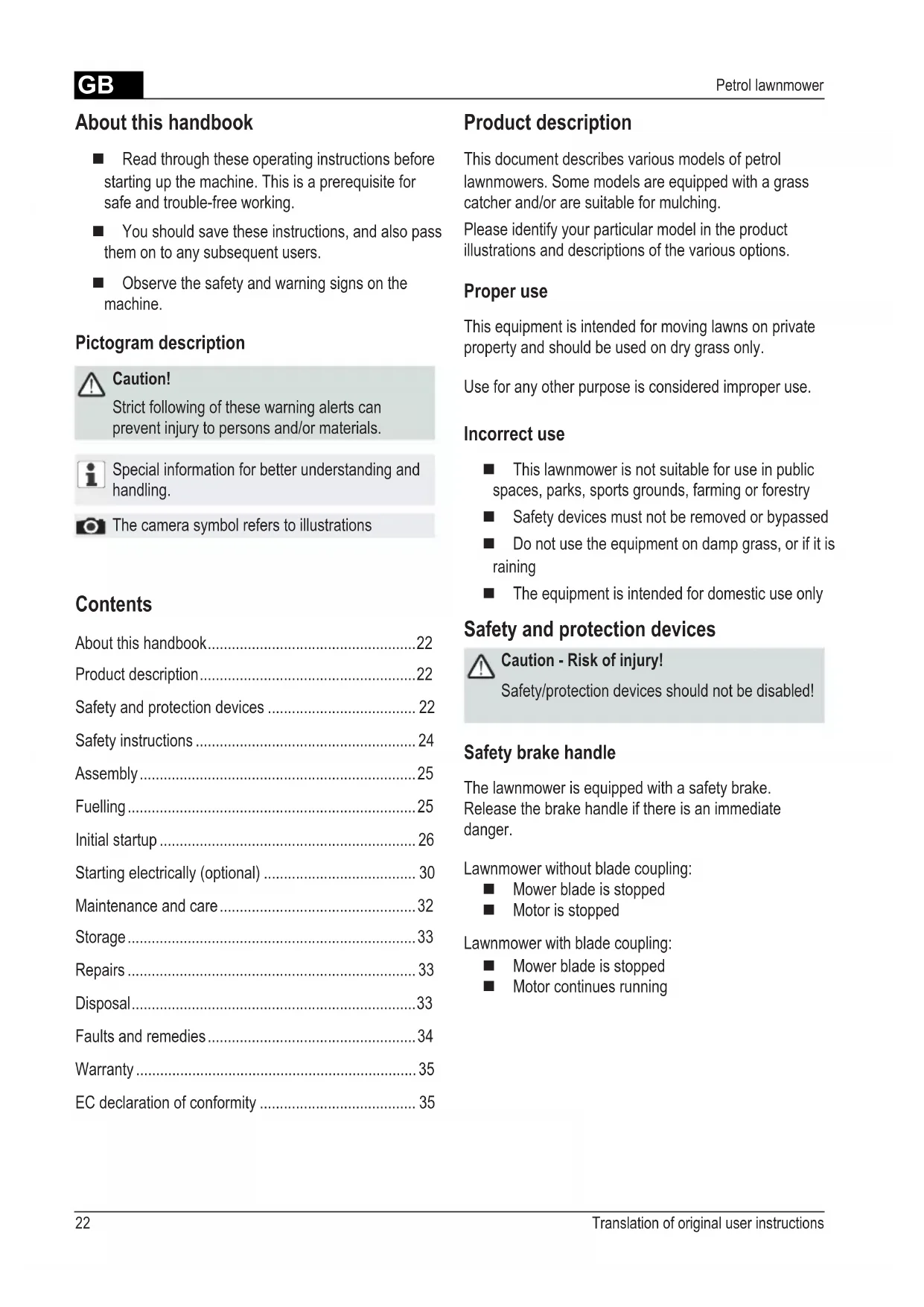
Pictogram description

Caution!
Strict following of these warning alerts can prevent injury to persons and/or materials.

Special information for better understanding and handling.

The camera symbol refers to illustrations
Contents
About this handbook....22
Product description....22
Safety and protection devices 22
Safety instructions 24
Assembly 25
Fuelling 25
Initial startup 26
Starting electrically (optional) 30
Maintenance and care 32
Storage 33
Repairs 33
Disposal....33
Faults and remedies....34
Warranty 35
EC declaration of conformity 35
Product description
This document describes various models of petrol lawnmowers. Some models are equipped with a grass catcher and/or are suitable for mulching.
Please identify your particular model in the product illustrations and descriptions of the various options.
Proper use
This equipment is intended for moving lawns on private property and should be used on dry grass only.
Use for any other purpose is considered improper use.
Incorrect use
■ This lawnmower is not suitable for use in public spaces, parks, sports grounds, farming or forestry
■ Safety devices must not be removed or bypassed
■ Do not use the equipment on damp grass, or if it is raining
■ The equipment is intended for domestic use only
Safety and protection devices

Caution - Risk of injury!
Safety/protection devices should not be disabled!
Safety brake handle
The lawnmower is equipped with a safety brake. Release the brake handle if there is an immediate danger.
Lawnmower without blade coupling:
■ Mower blade is stopped
■ Motor is stopped
Lawnmower with blade coupling:
■ Mower blade is stopped
■ Motor continues running
Deflector plate
The deflector plate provides protection against any projectiles thrown up.
text_image
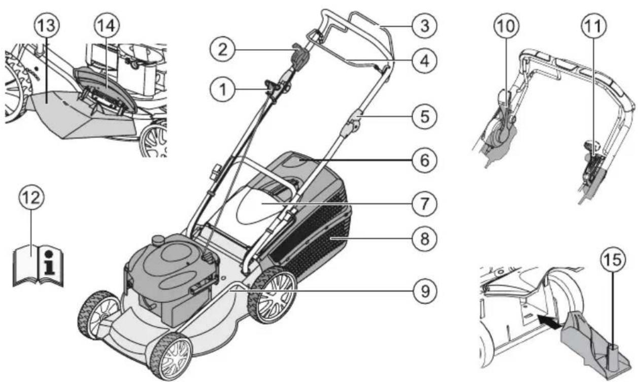
Technical diagram of a lawn mower with numbered parts and labeled parts, including front, side, and top views.| 1 Starter cable 9 Cutting height adjustment* | ||
| 2 Start, stop* 10 Blade coupling* | ||
| 3 Wheel drive* 11 Vario transmission* | ||
| 4 Safety brake handle 12 Operating instructions | ||
| 5 Ergonomic height adjustment* 13 Outlet shaft insert* | ||
| 6 Fill level indicator* 14 Cover flap* | ||
| 7 Deflector plate* 15 Mulch kit* | ||
| 8 Grass catcher* * depending on version |
Symbols on the device
 | Caution!Be particularly careful when handling. | Remove the spark plug connector before working on the cutting gear. | |
 | Before initial startup read the instructions for use! Release the motor brake. | ||
 | Keep other people out of the danger area! Switch on the wheel drive. | ||
 | Keep hands and feet away from the cutting gear! | Remote throttle control Start / Stop. | |
 | Keep away from the danger area. | ||
Additional symbols on lawnmowers with Electrostart

Caution! Risk of electric shock.

Keep the connection line away from the mower blades.

If the cable is damaged, or when carrying out maintenance work, always disconnect the equipment from the mains supply.
Safety instructions

Caution!
Use the equipment only if it is in correct operating condition!

Caution - Risk of injury!
Safety/protection devices should not be disabled!

Caution - risk of fire!
After fuelling, do not store the machine in buildings where the petrol fumes might come into contact with naked flames or sparks!
Keep the area around the motor, exhaust, battery case, and fuel tank clear of grass cuttings, petrol and oil.
- Keep other people out of the danger area
■ The machine operator or user is responsible for any accidents affecting other people or their property
■ Children, or any persons who have not read these operating instructions, should not be allowed to use this machine
■ Follow the local regulations regarding the minimum age for operators of this type of machine
■ Do not use the equipment if under the influence of alcohol, drugs or medication
■ Wear appropriate work clothes
Long trousers
Hard, non-slip shoes
■ Hearing protection
■ If working on slopes
■ always make sure you are positioned securely
■ always work across the slope, never upward or downward
do not work on slopes where the gradient is greater than 20^
■ Only use the lawnmower if there is sufficient daylight or artificial lighting
- Keep the body, limbs and clothing away from the cutting gear
■ Follow the hours of use regulations applying in the country concerned
■ Do not leave the equipment unattended when ready to operate
■ Only use the lawnmower if the mower blade is sharp
■ Do not operate the equipment if the safety devices / protective grilles are damaged
■ Never operate the equipment if the safety devices are not fully assembled (e.g. deflector plate, grass catching devices)
■ Before each use, check the equipment for damage; replace any damaged parts before using again
■ Switch off the motor, wait for the equipment to come to a standstill, then pull out the spark plug connector
■ if leaving the equipment unattended
■ if a fault has occurred
■ before clearing blockages
■ before removing obstructions
■ if the lawnmower has run into foreign objects

Check the lawnmower for damage, and carry out the necessary repairs before restarting or using the lawnmower again.
■ Insert the spark plug connector and start the motor
■ after correcting the fault (see Faults table) and checking the equipment
■ after cleaning the equipment
■ Carefully check the ground to be mowed, and remove any foreign objects
■ Take particular care when turning the lawnmower around, or if pulling it towards you
■ Do not mow over obstacles (such as branches, tree roots)
■ Remove cuttings only when the motor has stopped
■ Switch off the motor / mower blade when passing over areas other than those that have to be mowed
■ Never lift or carry the equipment while the motor is running
■ Do not eat or drink when topping up the petrol or motor oil
■ Do not inhale the petrol fumes
Assembly
Follow the accompanying assembly instructions.

Caution!
The equipment can be used only after complete assembly.
Fuelling
Fill the lawnmower with fuel before the initial startup.

Warning - risk of fire!
Petrol and oil are highly inflammable!

Always observe the operating instructions supplied by the motor manufacturer.
Operating fluids
| Petrol Motor oil | ||
| Grade Regular petrol / unleaded | Refer to the motor manufacturer's instructions | |
| Filling capacity | Refer to the motor manufacturer's instructions | about 0.6 l |
Safety

Warning!
Never leave a motor running in an enclosed space. Toxic hazard!
■ Store petrol and oil only in containers intended for this purpose
■ Only add or drain oil in the open air, and when the motor has cooled down
■ Do not add petrol or oil while the motor is running
■ Do not overfill the tank (petrol expands)
■ Do not smoke when refuelling
■ Do not open the tank lock when the motor is running or when hot
■ Replace the tank or tank lock if damaged
■ Always close the tank cap firmly
■ If petrol has been spilt:
Do not start the motor
Do not start the equipment
Clean the equipment
■ If motor oil has been spilled:
Do not start the motor
Soak up the spilled oil with an oil binding agent and dispose of appropriately
Clean the equipment

Used oil should not be:
■ disposed of with domestic rubbish
■ poured into the sewage system, drains, or onto the ground
We recommend to collect the used oil in a closed container and to deliver it to a suitable recycling or service station.
Adding petrol
- Unscrew the tank cap, and keep in a clean place.
- Pour in petrol using a funnel.
- Firmly replace the cap on the filler opening and clean it.
Adding motor oil
- Unscrew the filler cap, and keep in a clean place.
- Pour in oil using a funnel.
- Firmly replace the cap on the filler opening and clean it.
Initial startup

Caution!
The equipment should not be used if the cutting gear and/or fastenings are loose, damaged or worn.
Carry out a visual inspection before each start-up.

The camera symbol on the following page refers to the illustrations on Page 4–7.
Adjusting the cutting height

Caution - Risk of injury!
Adjust the cutting height only with the motor switched off and when the mower blade has come to a standstill.

- Always set all the wheels to the same cutting height.
- Cutting height adjustment depends on the particular model.
Central adjustment (☐)
- Press and hold the central height adjustment knob (d/1).
For shorter grass, press the central adjustment handle downward (C/2)
For longer grass, pull the central adjustment handle upward (6/2)
The central height adjustment level is indicated (C/3)
- Release the knob at the desired cutting height.
Axle adjustment or central adjustment (☐, 3)
- To release the lever, press to the side and hold.
- Push the lever to the left or right to select the desired cutting height.
- Let the lever click into position.
- Check that all wheels are set to the same position.
Quick adjustment of individual wheels or axle adjustment (4)
- To release the lever, press to the side and hold.
- Push the lever to the left or right to select the desired cutting height.
- Let the lever click into position.
- Check that all wheels are set to the same position.
Individual wheel adjustment (5)
- Loosen the wheel bolt.
- Insert the wheel bolt in the hole corresponding to the desired cutting height.
- Tighten the wheel bolt.
- Check that all wheels are set to the same position.
Central axle adjustment (6)
- Place a thumb at each end of the axle.
- Place the fingers under the mower housing.
- Using both thumbs, press the axle out of its present height setting notch.
- Using both thumbs, push the axle to the desired height setting notch, then allow it to engage.
- Check that all wheels are set to the same position.
Mowing with the grass catcher

Caution - Risk of injury!
Attach/detach the grass catcher only when the motor is switched off and the mower blade has come to a standstill.
- Lift the deflector plate and insert the grass catcher in the holders (☐).
Fill level indicator
The fill level indicator is pushed upward by the air flow when mowing (da).
If the grass catcher is full, the indicator points to the box (☐b). The grass catcher must be emptied.
Emptying the grass catcher
- Lift the deflector plate.
- Unhook the grass catcher and pull backward to remove (6).
- Empty the grass catcher.
- Lift the deflector plate and insert the grass catcher in the holders (a).
Mowing without the grass catcher

Caution!
Only work without the grass catcher if the deflector plate torsion spring is working correctly.
The deflector plate is held to the mower spring force. This causes the mowed grass to be thrown backward and downward.
Mulching with the mulch kit (optional)
When mulching, the grass cuttings are not collected, but are left on the lawn. The grass mulch prevents the soil from drying out, and supplies it with nutrients.
The best results are obtained by cutting back regularly by about 2 cm. Only young grass with a soft leaf texture decomposes quickly.
■ Grass height before mulching: 8 cm maximum
■ Grass height after mulching: 4 cm minimum

Adapt your walking pace to the mulching process, do not walk too fast.
Inserting the mulch kit

Caution - Risk of injury!
Insert/remove the mulch kit only with the motor switched off and when the mower blade has come to a standstill.
- Remove the grass catcher ( 6)
- Lift the deflector plate and insert the mulch kit in the outlet shaft (c). It must lock into place.

If the mulch kit is not locked into position, both the mulch kit and the mower blade may be damaged.
Removing the mulch kit
- Lift the deflector plate.
- Release the lock on the mulch kit (10/1).
- Pull out the mulch kit (10/2).
housing by
Mowing with the side outlet duct (optional)

Caution - risk of injury!
Attach/detach the side outlet only when the motor is switched off and the mower blade has come to a standstill.
Inserting the side outlet
- Remove the grass catcher and insert the mulch kit.
- Fold up the side outlet cover and hold it ( 1/1).
- Insert the side outlet duct ( 14/2).
- Slowly close the cover.
The cover holds the side outlet duct and prevents it falling out.
Removing the side outlet
- Fold up the side outlet cover and hold it ( 1/1).
- Remove the side outlet and close the cover (1/2).
Setting the handle height (optional)
Knob adjustment
- Press and hold both knobs on the handlebar and select the desired position (☐12/1).
- Release the knobs to lock the handlebar in position.
Clamp adjustment
- Hold the bar and loosen both clamps ( 12/2).
- Move the bar to the desired position
- Lock the clamps.
Starting the motor

Caution - risk of poisoning!
Never leave a motor running in an enclosed space.

Caution - Risk of injury!
Do not tilt the lawnmower while starting.

- Start the motor only when the blade is mounted (the blade acts as a flywheel mass)
- If starting the motor when hot do NOT use the choke or primer button
- Do not change the motor controller settings
■ Do not start the equipment if the outlet shaft is not covered by one of the following parts:
Grass catcher
Deflector plate
Mulch kit
■ Be particularly careful when operating the starter switch - follow the manufacturer's instructions
- Keep your feet at a safe distance from the cutting gear
■ Start the lawnmower where the grass is shorter
Position symbols on the equipment:
| Choke*On Off |  |  |
| Remote throttle control*Start Stop |  |  |
| Remote throttle control with choke* |  |  |
| Vario transmission*Fast Slow |  |  |
| Blade coupling*On Off |  |  |
* depending on version
Starting manually
without remote throttle control, with choke
| ChokeOn Off |  |
- Set the choke at position 1 (10/1).
- Pull in the safety brake handle on the handlebar and hold it (17) – the brake handle does not lock.
- Pull out the starter cord sharply, then allow it to slowly rewind (☐8).
- When the motor has warmed up (about 15–20 seconds), set the choke to position 2 (3/2).

Motor speed (rpm value) is fixed. Motor speed cannot be adjusted.
without remote throttle control, with primer (C16)
- Press the primer button 3 times at intervals of about 2 seconds (6). If the temperature is below 10 °C, press the primer button 5 times.
- Pull in the safety brake handle on the handlebar and hold it (17) – the brake handle does not lock.
- Pull out the starter cord sharply, then allow it to slowly rewind (☐8).

Motor speed (rpm value) is fixed. Motor speed cannot be adjusted.
without remote throttle control, without primer/choke
- Pull in the safety brake handle on the handlebar and hold it (17) – the brake handle does not lock.
- Pull out the starter cord sharply, then allow it to slowly rewind (c18).

Motor speed (rpm value) is fixed. Motor speed cannot be adjusted.
with remote throttle control, with choke
| Remote throttle control with choke |  |
- Set the throttle lever to position (141).
- Pull in the safety brake handle on the handlebar and hold it (17) – the brake handle does not lock.
- Pull out the starter cord sharply, then allow it to slowly rewind (8).
- When the motor has warmed up (about 15–20 seconds), set the throttle lever to a position between and (14/2)
with remote throttle control, without primer/choke
| Remote throttle control Start Stop |  |
- Set the throttle lever to position 📋 (20/1).
- Pull in the safety brake handle on the handlebar and hold it (17) - the brake handle does not lock.
- Pull out the starter cord sharply, then allow it to slowly rewind (☐8).
- When the motor has warmed up (about 15–20 seconds), set the throttle lever to a position between and (-20).
with remote throttle control, with primer (☐ 16)
Remote throttle control
Start Stop

-
Set the throttle lever to position (20(1)).
-
Press the primer button 3 times at intervals of about 2 seconds (6). If the temperature is below 10 °C, press the primer button 5 times.
- Pull in the safety brake handle on the handlebar and hold it (17) - the brake handle does not lock.
- Pull out the starter cord sharply, then allow it to slowly rewind (18).
- As soon as the motor starts running, set the throttle lever for the desired motor rpm, at a position between and (\~20).
Starting electrically (optional)
Electrostart with primer (6)
- Set the throttle lever to the "START" position (☐5/1).
- Press the primer button 3 times at intervals of about 2 seconds (16). If the temperature is below 10 °C, press the primer button 5 times.
- Pull in the safety brake handle on the handlebar and hold it (c7) – the brake handle does not lock.
- Turn the ignition key fully to the right in the ignition lock (C19).
- As soon as the motor starts running, release the ignition key (it returns automatically to position "0").
- According to the desired motor speed, set the throttle lever to a position between and (15/2).
Electrostart without primer/choke (15)
- Set the throttle lever to the "START" position (45/1).
- Pull in the safety brake handle on the handlebar and hold it (47) – the brake handle does not lock.
- Turn the ignition key fully to the right in the ignition lock (c19).
- As soon as the motor starts running, release the ignition key (it returns automatically to position "0").
- According to the desired motor speed, set the throttle lever to a position between and (45/2).
Blade coupling (optional)
Blade coupling
On
Off


With the blade coupling, the mower blade can be engaged or disengaged while the motor is running.
Engaging the blade coupling
- Pull in the safety brake handle on the handlebar and hold it (C47) - The brake handle does not lock.
- Push the coupling lever away from you (24/1) - The blade coupling is engaged.
Disengaging the blade coupling.
-
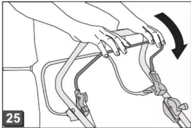
Release the safety brake handle (15).
-
The blade coupling is disengaged.
- The coupling lever moves to rest position (21/2).
Turn the motor off
Lawnmower without blade coupling
- Set the throttle lever to position (20/2)
- Release the safety brake handle ( 26).
- The motor is switched off.

Caution - danger of serious cut injuries!
The motor may continue running. After switching off, make sure the motor has stopped turning.
Lawnmower with blade coupling
Blade coupling
On
Off


-
Release the safety brake handle (25).
-
Set the throttle lever to position (20/2)
- The motor is switched off.

Caution - danger of serious cut injuries!
The motor may continue running. After switching off, make sure the motor has stopped turning.
Wheel drive (optional) (2)

Caution!
Engage the transmission only when the motor is running.
Switching on the wheel drive
- Press the transmission control handle against the handlebar and hold it (2) – the transmission control handle does not lock.
- The wheel drive is switched on.
Switching off the wheel drive
- Release the transmission control handle (24).
- The wheel drive is switched off.
Vario transmission (Speed Control) (optional)
Vario transmission
Fast
Slow


The Vario transmission allows continuous variation of the ground speed of the lawnmower.

Caution!
Operate the lever only when the motor is running. Operating the lever without the motor drive may damage the drive mechanism.
■ To increase the speed, pull the lever (23) towards (3/2)
■ To lower the speed, pull the lever (☐ 23) towards (☐ 3/1)

Always adjust the ground speed to suit the current ground and lawn conditions.
Maintenance and care

Caution - Risk of injury!
- Before carrying our any care or maintenance work, always switch off the motor and pull out the spark plug connector.
- The motor may continue running. After switching off, make sure the motor has stopped turning.
-
Always wear working gloves when carrying out maintenance or repair work.
-
Check the grass catcher regularly for wear, and to ensure it is working correctly
■ Clean the equipment after each use
■ Do not wash the equipment by hosing or spraying with water
Water infiltration can cause faults (in the ignition system, carburettor)
■ Check the mower blade regularly for damage
■ Always replace the muffler if faulty
Tilting the lawnmower
Depending on the motor manufacturer:
■ the carburettor / air filter must be facing upward (26)
■ the spark plug must be facing upward (27)

Follow the operating instructions of the motor manufacturer!
Resharpening/replacing the mower blade
■ Blunt or damaged blades should be resharpened / replaced only at a service point or by an authorised specialist
■ Resharpened blades must be rebalanced

Caution!
Blades that have not been rebalanced can cause serious vibrations, and may result in damage to the lawnmower.
Charging the starter battery (optional)
The starter battery is maintenance-free and is normally charged by the lawnmower.
In certain cases, however, the battery will need to be charged by the user:
■ Before the initial start-up of the lawnmower
If discharged, before the winter season, or if left unused for long periods (> 6 months)
Charging procedure:
- Take the battery charger out of the battery box.
- Disconnect the battery cable from the motor cable (198).
- Connect the battery cable with the charger cable (☐9).
- Connect the charger to the mains supply. The mains voltage must match the operating voltage of the charger.
The required charging time is about 36 hours.
Use only the original battery charger supplied.

Caution!
- Charge the starter battery only in dry, well-ventilated rooms.
- Do not start up the lawnmower while the battery is charging.
Care of the motor
Changing the motor oil
- Have a suitable container ready to collect the used oil.
- Drain or suction off all the oil through the oil filler opening.

Dispose of used motor oil in a manner that is compatible with the environment!
We recommend to collect the used oil in a closed container and to deliver it to a suitable recycling or service station.
Used oil should not be
- disposed of with domestic rubbish
- poured into the sewage system or drains
- poured out onto the ground
Changing the air filter
■ Follow the instructions of the manufacturer of the motor.
Changing the spark plug
■ Follow the instructions of the manufacturer of the motor.
Wheel drive (optional)
Adjusting the Bowden cable
If the wheel drive can no longer be switched on or off while the motor- is running, the related Bowden cable needs to be adjusted.

Caution!
Adjust the Bowden cable only when the motor is switched off.
- Turn the adjuster on the Bowden cable in the direction of the arrow (☐0).
- To test the cable setting, switch on the motor and switch on the wheel drive.
- If the wheel drive is still not working, the lawnmower must be taken to a service point or an authorised specialist.
Lubricating the drive pinion
■ From time to time, lubricate the drive pinion on the transmission shaft

The wheel drive gearing is maintenance free.
Storage

Caution - risk of explosion!
Do not store the equipment where there are naked flames or heat sources.
■ Allow the motor to cool down
■ To save storage space, fold the handlebar down (1, 32)
■ Store the equipment in an area which is kept dry, and which cannot be accessed by children or unauthorised persons
■ Store the starter battery where it will be protected from frost
■ Recharge the starter battery from time to time
- Drain the fuel tank
■ Pull out the spark plug connector
Repairs
Repairs should be carried out only by a service point or an authorised specialist.
Disposal
Do not dispose of old equipment, batteries or accumulators as household waste!
Machine, packaging, and accessories were made with recyclable materials, and should be disposed of accordingly.
Faults and remedies

Caution!
The motor shaft and mower blade should not be aligned.
| Fault Solution | |
| The motor does not start • Add petrol• Set throttle lever to "Start"• Switch on the choke• Press the motor switch at the handlebar• Check the spark plugs and replace if necessary.• Clean the air filter.• Spin the mower blade• Recharge the starter battery• Start on a surface already mowed | |
| Motor power reduced • Adjust the cutting height• Resharpen / replace the mower blade• Clean the outlet shaft/housing• Clean the air filter.• Reduce the working speed | |
| Lawnmower cuts unevenly • | Resharpen/replace the mower blade• Adjust the cutting height |
| Grass catcher does not fill sufficiently | • Adjust the cutting height• Allow the lawn to dry• Resharpen/replace the mower blade• Clear the grille on the grass catcher• Clean the outlet shaft/housing |
| Wheel drive does not work • | Adjust the Bowden cable• V-belt faulty• Contact the service-workshop• Clean any dirt away from the wheel drive, toothed belt and gearing• Lubricate the freewheels (drive pinion on drive shaft) with spray oil |
| Wheels do not turn when the transmission is switched on | • Retighten the wheel bolts• Wheel hub faulty• V-belt faulty• Contact the service-workshop |
| Unusually strong vibrations in the lawnmower | • Check the mower blade |

For faults not listed in this table, or which you cannot resolve by yourself, please contact our customer service.
■ Always have the equipment checked out by a professional in the following cases:
■ after bumping against an obstacle
■ if the motor stops suddenly
■ if there is damage to the transmission
■ if the V-belt is faulty
if the blade is bent
■ if there is warping of the motor shaft
EC declaration of conformity
■ see assembly instructions
Warranty
If any material or manufacturing defects are found during the statutory customer protection period, we will either repair or replace the equipment, whichever we consider the more appropriate. This statutory period may vary according to the legislation in force in the country where the equipment was purchased.
Our warranty is valid only if: The warranty is no longer valid if:
■ The equipment has been used properly
■ The operating instructions have been followed
■ Genuine replacement parts have been used
■ The equipment has been tampered with
■ Technical modifications have been made
■ The equipment was not used for its intended purpose (for example, used for commercial or communal applications)
The following are not covered by warranty:
■ Paint damage due to normal wear
■ Wear parts identified by a border XXXXX (X) on the spare parts list
- Combustion motors – these are covered by a separate warranty from the manufacturer concerned
To make a claim under warranty, please take this statement of warranty and proof of purchase to the nearest authorised customer service centre. This warranty does not affect the usual statutory rights of the customer relative to the seller.
Over dit handboek
text_image
Technical diagram of a lawn mower with numbered parts and labeled parts, including front, side, and top views.text_image
Technical diagram of a lawn mower with numbered parts and exploded views, including front, side, and top views.text_image
Technical diagram of a lawn mower with numbered parts and exploded views, including front, side, and top views.text_image
Technical diagram of a lawn mower with numbered parts and exploded views, including front, side, and top views.text_image
Technical diagram of a lawn mower with numbered parts and exploded views, including front, side, and top views.text_image
Technical diagram of a lawn mower with numbered parts and exploded views, including open book and mechanical components.| 1 Vrv zaganjalnika 9 Nastavitev višine rezanja* | ||
| 2 Start, Stop* 10 Sklopka rezila* | ||
| 3 Kolesni pogon* 11 Menjalnik Vario* | ||
| 4 Varnostno streme 12 Navodila za uporabo | ||
| 5 Ergonomska nastavitev višine* 13 Vstavek za izmetavanje* | ||
| 6 Kazalnik nivoja napolnjenosti* 14 Zaporna loputa* | ||
| 7 Prestrezni zaklop* 15 Komplet za zastiranje* | ||
| 8 Zbiralna košara za travo* * odvisno od izvedbe |
Simboli na napravi
text_image
Technical diagram of a lawn mower with numbered parts and labeled parts, including front, side, and top views.| 1 Uže pokretača 9 Namještanje visine rezanja* | ||
| 2 Start, stop* 10 Spojka noža za rezanje* | ||
| 3 Pogon kotača* 11 Vario prijenosnik* | ||
| 4 Sigurnosni stremen 12 Upute za uporabu | ||
| 5 Ergonomsko namještanje visine* 13 Nastavak za izbacivanje* | ||
| 6 Pokazatelj razine napunjenosti* 14 Zatvarač* | ||
| 7 Zaklopac 15 Komplet za malčiranje* | ||
| 8 Košara* * ovisno o izvedbi |
Simboli na uređaju
 | Pozor!Naročit oprez pri rukovanju. |  | Prije radova na alatu za rezanje izvucite utikač svjećice. |
 | Prije puštanja uređaja u rad pročitajte upute za uporabu! |  | Otpustite kočnicu motora. |
 | Ostale osobe držite dalje od područja opasnosti! Uk |  | kotača. |
 | Šake i stopala držite podalje od alata za rezanje! |  | Daljinsko upravljanje gasom Start / Stop. |
 | Održavajte razmak od opasnih područja. | ||
Dodatni simboli kod uređaja s električnim pokretanjem

natural_image
Simple line drawing of a rabbit, a triangle, and a turtle (no text or symbols)- Polugu gasa postavite na položaj 📋 (20/1).
- Sigurnosni stremen izvucite do gornje priječnice i čvrsto ga držite (17) - sigurnosni stremen ne uskače u ležište.
- Naglo izvucite uže startera i zatim ga pustite da se ponovno polako uvuče (18).
- Nakon zagrijavanja motora (oko 15–20 sekundi) postavite polugu gasa na položaj između 📄 i 🏶 (📞0).
s daljinskim upravljanjem gasom, s prajmerom (6)
Daljinsko upravljanje gasom Start Stop

- Polugu gasa postavite na položaj 📋 (20/1).
- Pritisnite gumb prajmera 3x u vremenskom razmaku od oko 2 sekunde (6). Kod temperatura ispod 10 °C gumb prajmera pritisnite 5x.
- Sigurnosni stremen izvucite do gornje priječnice i čvrsto ga držite (17) - sigurnosni stremen ne uskače u ležište.
- Naglo izvucite uže startera i zatim ga pustite da se ponovno polako uvuče (8).
- Čim se motor pokrene, postavite polugu gasa za željeni broj okretaja motora u položaj između 📄 i 🏠 (0).
Električno pokretanje (opcija)
Električno pokretanje s prajmerom (6)
- Polugu gasa postavite na položaj "START" (15/1).
- Pritisnite gumb prajmera 3x u vremenskom razmaku od oko 2 sekunde (616). Kod temperatura ispod 10 °C gumb prajmera pritisnite 5x.
- Sigurnosni stremen izvucite do gornje priječnice i čvrsto ga držite (17) – sigurnosni stremen ne uskače u ležište.
- Ključ za paljenje u bravi okrenite do kraja udesno (c19).
- Čim se motor pokrene, pustite ključ za paljenje (vraća se na položaj "0").
- Polugu gasa u skladu sa željenim brojem okretaja motora postavite u položaj između i (25/2).
Električno pokretanje bez prajmera/čoka (15)
- Polugu gasa postavite na položaj "START" (45/1).
- Sigurnosni stremen izvucite do gornje priječnice i čvrsto ga držite (17) – sigurnosni stremen ne uskače u ležište.
- Ključ za paljenje u bravi okrenite do kraja udesno (19).
- Čim se motor pokrene, pustite ključ za paljenje (vraća se na položaj "0").
- Polugu gasa u skladu sa željenim brojem okretaja motora postavite u položaj između 📋 i 🙏 (45/2).
Spojka noža za rezanje (opcija)
Spojka noža za rezanje Uklj Isklj


Spojkom noža za rezanje može se ukopčati i iskopčati nož za rezanje dok motor nastavlja raditi.