ET600 - Measuring equipment Klein Tools - Free user manual and instructions
Find the device manual for free ET600 Klein Tools in PDF.
User questions about ET600 Klein Tools
0 question about this device. Answer the ones you know or ask your own.
Ask a new question about this device
Download the instructions for your Measuring equipment in PDF format for free! Find your manual ET600 - Klein Tools and take your electronic device back in hand. On this page are published all the documents necessary for the use of your device. ET600 by Klein Tools.
USER MANUAL ET600 Klein Tools
- CONTINUITY ET600 1000V
CAT IV 600V CAT III 1000V2 GENERAL SPECIFICATIONS The Klein Tools ET600 is a digital tester with four voltage ranges for insulation resistance measurements, and is also a True Root-Mean- Squared (TRMS) tester that measures AC/DC voltage, electrical resistance, and continuity.
- Operating Altitude: 6562 ft. (2000m)
- Relative Humidity: <80% non-condensing
- Operating Temp: 14°F to 122°F (-10°C to 50°C)
- Storage Temp: -4°F to 140°F (-30°C to 60°C)
- Accuracy: Values stated at 65°F to 83°F (18°C to 28°C)
- Temp Coef cient: 0.1 x (Quoted Accuracy) per °C above 28°C or below 18°C, corrections are required when ambient working temp is outside of Accuracy Temp range
- Battery Life with fresh alkaline batteries (EN61557): Insulation test: Tester performs at least 137 insulation tests of 1000V DC into 1MΩ with a duty cycle of 5 seconds on and 25 seconds off. Resistance measurement: Tester performs at least 265 resistance measurements of 1Ω with a duty cycle of 5 seconds on an 25 seconds off.
- Calibration: Accurate for one year
- Accuracy: ±(% of reading + # of least significant digits)
- Drop Protection: 3.3 ft. (1 m)
- Ingress Protection: IP40* *except test lead jacks, see WARNINGS section
- Safety Rating: CAT IV 600V, CAT III 1000V, Class 2, Double insulation CAT III: Measurement category III is applicable to test and measuring circuits connected to the distribution part of the building’s low-voltage MAINS installation. CAT IV: Measurement category IV is applicable to test and measuring circuits connected at the source of the building’s low-voltage MAINS installation.
- Electromagnetic Environment: IEC EN 61326-1. This equipment meets requirements for use in basic and controlled electromagnetic environments like residential properties, business premises, and light-industrial locations. Specifications subject to change. ENGLISH
400 to 4000 1 ±(4% + 5 digits) 500V (0% to +20%)
400 to 4000 1 ±(4% + 5 digits) VOLTAGE Function Voltage Resolution Accuracy ( 50–60 Hz
- Before each use, verify meter operation by measuring a known voltage.
- DO NOT use the meter on a circuit with voltages that exceed the category based rating of this meter.
- DO NOT use the meter during electrical storms or in wet weather.
- DO NOT use the meter or test leads if they appear to be damaged.
- Use ONLY with CAT IV rated test leads.
- Ensure meter leads are fully seated, and keep fingers away from the metal probe contacts when making measurements.
- DO NOT open the meter to replace batteries while the probes are connected.
- Use caution when working with voltages above 25V AC RMS or 60V DC. Such voltages pose a shock hazard.
- To avoid false readings that can lead to electrical shock, replace batteries when a low battery indicator appears.
- DO NOT attempt to measure resistance or continuity on a live circuit.
- Make sure the circuit under test does not include components that can be damaged by 1000VDC; such devices include power factor correction capacitors, low voltage mineral insulated cables, electronic light dimmers, and ballast/starters for fluorescent lamps.
- DO NOT perform insulation resistance testing or earth-bond resistance testing if voltage is present on parts of an installation or equipment under test. Circuits under test (except for voltage measurements) must be de-energized and isolated before connections are made.
- Circuit connections must not be touched during a test. Accidental contact with conductors could result in electrical shock.
- After insulation resistance testing, make sure the circuit is fully discharged before removing test leads. LCD should read close to zero volts.
- Always adhere to local and national safety codes. Use personal protective equipment to prevent shock and arc blast injury where hazardous live conductors are exposed.
- Meter is IP40 dust & water resistant, except for the test lead jacks. Following any contact with water, thoroughly dry meter and test lead jacks prior to subsequent use. INFLUENCE VARIABLES AND UNCERTAINTIES (EN61557) Code Variable Range % Within Range E1 Position +/- 90° <5% E2 Supply voltage
AC Voltage DC Voltage Resistance (Ohms) Audible Continuity Fuse (with rating below symbol) Double Insulated Class II Read Instructions Warning or Caution To ensure safe operation and service of this meter, follow all warnings and instructions detailed in this manual. Risk of Electrical Shock Improper use of this meter can lead to risk of electrical shock. Follow all warnings and instructions detailed in this manual.
Data Hold Audible Continuity AC (Alternating Current) DC (Direct Current) Low Battery Auto Power Off Maximum Value Minimum Value Mega (value x 10
Volts Ohms Test Voltage Test Lock Bar Graph Negative Greater Than Zero Adjustment NOTE: The bar graph provides a visual indication of the measurement value, showing voltage for VAC / VDC, and showing resistance for insulation resistance testing.6 ENGLISH FEATURE DETAILS
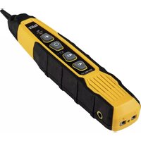
from the OFF setting to any measurement setting. To Power OFF the meter, rotate the Function Selector switch to the OFF setting. NOTE: The meter will automatically power OFF after 15 minutes of inactivity. To disable auto-power off, press and hold the "HOLD" button
Press and hold the Backlight button for more than one second to turn the backlight on or off. The backlight will automatically turns off after approximately 3 minutes. ZERO BUTTON
Press the zero button for automatic zero adjustment for voltage and resistance.
When the "MAX/MIN" button is pressed, the meter keeps track of the minimum and maximum value of the measurement for VAC, VDC, continuity, and ohms. The first press of the MAX/MIN button displays the MAX value, the second press displays the MIN value. To return to normal measuring mode, press and hold the "MAX/ MIN" button for more than one second.
"HOLD" (DATA HOLD) BUTTON
Press the "HOLD" button to hold the measurement on the display. Press again to release the display to return to live measuring (not for insulation resistance testing). LOCK BUTTON
For hands-free insulation resistance testing, use the Lock button feature. With the test leads connected to the equipment under test, press the Lock button for two seconds, and then press the TEST button to begin the test. The lock icon will appear on the display and the meter will beep to indicate it is in lock mode. Press the Test button to end the test. TEST BUTTON
With the test leads connected to the equipment under test, press and hold the TEST button to begin an insulation resistance test. The lower-right display will show test voltage, and the main display will show the resistance. NOTE: Make sure the circuit under test does not include components that can be damaged by 1000VDC; such devices include power factor correction capacitors, low voltage mineral insulated cables, electronic light dimmers, and ballast/starters for fluorescent lamps.8 ENGLISHENGLISH OPERATING INSTRUCTIONS
CONNECTING TEST LEADS
Do not test if leads are improperly seated. Results could cause intermittent display readings. To ensure proper connection, firmly press leads into the input jack completely. TESTING IN CAT III / CAT IV MEASUREMENT LOCATIONS Ensure the test lead shield is pressed firmly in place. Failure to use the CAT III / CAT IV shield increases arc-flash risk.
TESTING IN CAT II MEASUREMENT LOCATIONS
CAT III / CAT IV shields may be removed for CAT II locations. This will allow testing on recessed conductors such as standard wall outlets. Take care not to lose the shields. INCORRECT CORRECT 0.7" (18 mm) 5/32" (4 mm) 5/32 (4 mm) 5/32" (4 mm)9 OPERATING INSTRUCTIONS
INSULATION RESISTANCE MEASUREMENTS
1. Insert RED test lead into VΩ jack
, and BLACK test lead into COM jack
, and rotate the function selector to the desired test voltage. Choose from 125V, 250V, 500V, or 1000V based on the compatibility with the device tested. NOTE: Disconnect the circuit under test and isolate it from any stray resistance. Insulation test should only be performed on de-energized circuits.
2. Connect the Red and Black leads to the circuit under test. If there
is a voltage in the circuit, a constant beep will sound and the Test Voltage symbol will be displayed. Disconnect the circuit to proceed.
3. Press and hold the TEST button to begin test. The lower right
display shows test voltage, and the main display shows the resistance.
4. The measured insulation resistance is displayed on the main
display in MΩ. Allow the reading to stabilize before recording the measurement. Turning the function switch, at any time during the insulation test will end the testing process.
5. The circuit will discharge through the meter. Keep the test leads
connected until the circuit is completely discharged and the lower right display shows near zero volts. NOTE: Measurements can be adversely affected by impedances of additional operating circuits connected in parallel or by transient currents. NOTE: Overload “OL” for insulation resistance measurements is a value >4000 MΩ. LOCK FUNCTION For hands free testing, use the Lock feature for PI (Polarization Index) and DAR (Dielectric Absorption Ratio) testing. With the test leads connected to the equipment under test, press the "LOCK" button
to begin the test. The lock icon will appear on the display. The meter will beep to indicate it is in lock mode. To end the test at any time during the process, press the "TEST" button
to any other setting. Red leadBlack lead10 OPERATING INSTRUCTIONS ENGLISH CONTINUITY
1. Insert RED test lead into VΩ jack
, and BLACK test lead into COM jack
to the Continuity setting.
2. Remove power from circuit.
3. Test for continuity by connecting conductor or circuit with test
leads. If resistance is measured less than 40Ω, an audible signal will sound and display will show a resistance value indicating continuity. If circuit is open, display will show "OL". DO NOT attempt to measure continuity on a live circuit. Red leadBlack lead
AC/DC VOLTAGE MEASUREMENTS
1. Insert RED test lead into VΩ jack
, and BLACK test lead into COM jack
, and rotate the function selector to the AC Voltage or DC Voltage setting.
2. Apply test leads to the circuit to be tested to measure voltage.
NOTE: When measuring DC voltage, the main display shows the voltage measurement, the secondary display shows battery voltage. NOTE: When measuring DC voltage, if "–" appears on the LCD, the test leads are being applied to the circuit in reverse polarity. Swap the position of the leads to correct this. Red leadBlack lead11 FUSE REPLACEMENT
1. Remove screw from
with 6.3 x 31.7 mm, 500mA/1000V fast-blow 10kA fuse (Klein Cat. No. 69035).
3. Replace battery/fuse door and
fasten securely with screw. OPERATING INSTRUCTIONS MAINTENANCE BATTERY REPLACEMENT When indicator is displayed on LCD, batteries must be replaced.
1. Remove screw from battery/fuse door.
2. Replace 6 x 1.5V AA batteries (note proper polarity).
3. Replace battery/fuse door and fasten securely with screw.
To avoid risk of electric shock, disconnect leads from any voltage source before removing battery/fuse door. To avoid risk of electric shock, do not operate meter while battery/fuse door is removed. RESISTANCE MEASUREMENTS
1. Insert RED test lead into VΩ jack
, and BLACK test lead into COM jack
to the Resistance setting.
2. Remove power from circuit.
3. Measure resistance by connecting test leads to circuit.
NOTE: When in a Resistance setting and the test leads are open (not connected across a resistor), or when a failed resistor is under test, the display will indicate O.L. This is normal. DO NOT attempt to measure resistance on a live circuit. Red leadBlack lead12 ENGLISH CLEANING Be sure meter is turned off and wipe with a clean, dry lint-free cloth. Do not use abrasive cleaners or solvents. STORAGE Remove the batteries when meter is not in use for a prolonged period of time. Do not expose to high temperatures or humidity. After a period of storage in extreme conditions exceeding the limits mentioned in the General Specifications section, allow the meter to return to normal operating conditions before using.
See this product’s page at www.kleintools.com for FCC compliance information Canada ICES-003 (B) / NMB-003 (B) WARRANTY www.kleintools.com/warranty DISPOSAL / RECYCLE Do not place equipment and its accessories in the trash. Items must be properly disposed of in accordance with local regulations. Please see www.epa.gov/recycle for additional information. CUSTOMER SERVICE KLEIN TOOLS, INC. 450 Bond Street Lincolnshire, IL 60069 1-800-553-4676 customerservice@kleintools.com www.kleintools.comET600 ESPAÑOL
- Dimensions: 200mm x 92mm x 62mm (7,8po x 3,6po x 2,4po)