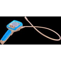
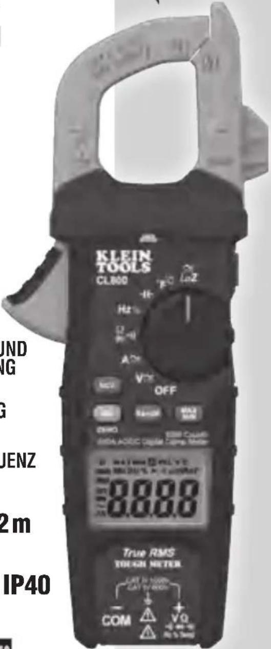
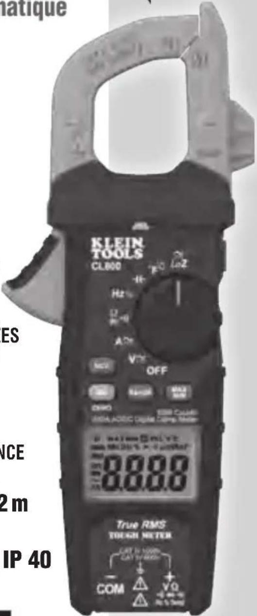
CL800 - Measuring equipment Klein Tools - Free user manual and instructions
Find the device manual for free CL800 Klein Tools in PDF.
| Product Type | TRMS Digital Clamp Meter with Auto-ranging |
| Brand | Klein Tools |
| Model | CL800 |
| Dimensions | 231 x 97 x 39 mm |
| Weight | 354 g (with batteries) |
| Power Supply | 2 AAA batteries (1.5 V) |
| Display | LCD 3-5/6 digits, 6000 counts |
| Safety Ratings | CAT IV 600 V, CAT III 1000 V, double insulation Class II |
| Measurement Functions | AC/DC Current (600 A), AC/DC Voltage (1000 V), Resistance, Continuity, Diode Test, Capacitance, Frequency, Duty Cycle, Temperature, Low Impedance (LoZ), Non-Contact Voltage (NCV) |
| Operating Temperature Range | 0 °C to 40 °C (32 °F to 104 °F) |
| Relative Humidity | < 80% non-condensing |
| Maximum Altitude | 2000 m |
| Drop Protection | 2 m |
| Sampling Frequency | 3 samples per second |
| Auto Power Off | After approximately 30 minutes of inactivity (disablable) |
| Special Features | Data Hold, Backlight, flashlight, MAX/MIN, DC ZERO |
| Thermocouple | Type K (with adapter), range -26 °C to 538 °C (-14 °F to 1000 °F) |
| Calibration | Valid for one year |
| Standards | UL 61010-1, 61010-2-032, 61010-2-033; CSA C22.2; IEC (EN) 61010-1, 61326-1 |
| Maintenance | Clean with a dry lint-free cloth, replace AAA batteries if low battery icon appears |
| Warranty | Visit www.kleintools.com/warranty |
Frequently Asked Questions - CL800 Klein Tools
User questions about CL800 Klein Tools
0 question about this device. Answer the ones you know or ask your own.
Ask a new question about this device
Download the instructions for your Measuring equipment in PDF format for free! Find your manual CL800 - Klein Tools and take your electronic device back in hand. On this page are published all the documents necessary for the use of your device. CL800 by Klein Tools.
USER MANUAL CL800 Klein Tools
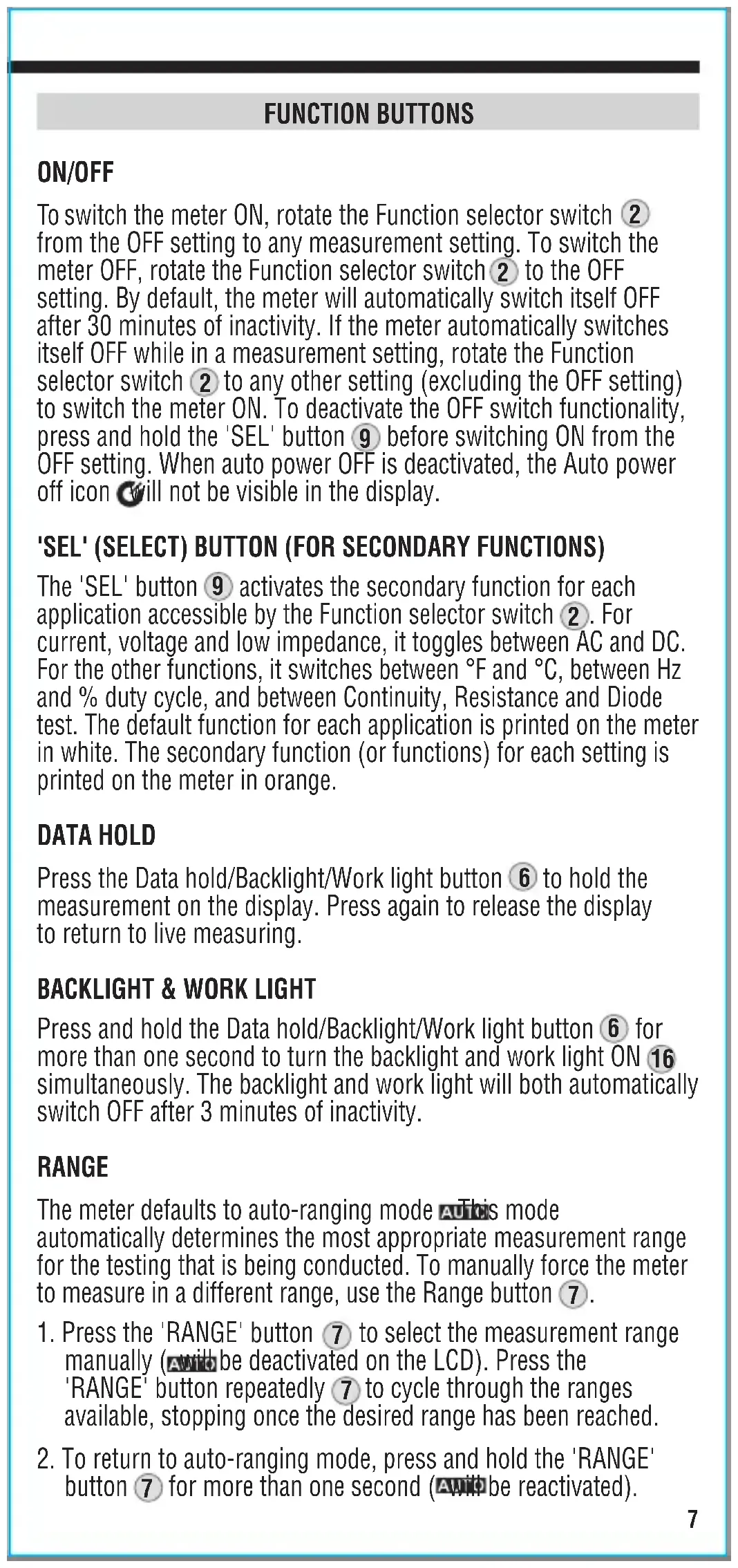
TOUGH METER
CE

Intertek
4007177

GENERAL SPECIFICATIONS
Klein Tools CL800E is an automatically ranging true root mean square (TRMS) digital clamp meter that measures AC/DC current via the clamp and measures AC/DC voltage, resistance, continuity, frequency and capacitance. It tests diodes via test leads and temperature via a thermocouple probe. It also features a Low impedance (LoZ) mode for identifying and eliminating ghost or stray voltages.
- Operating altitude: 2000 m
- Relative humidity: <80% non-condensing
- Operating temp: 0^ to 40^
• Storage temp: -10°C to 60°C
• Accuracy: Values stated at 18°C to 28°C - Temp coefficient: 0.1 × (quoted accuracy) per °C above 28°C or below 18°C. Corrections are required when the ambient working temp is outside the accuracy temp range
• Dimensions: 231 mm × 97 mm × 39 mm
• Weight: 354 g including batteries
• Calibration: Accurate for one year - Standards: Conforms to: UL STD 61010-1, 61010-2-032 and 61010-2-033.
Certified to: CSA STD C22.2 No. 61010-1, 61010-2-032 and 61010-2-033.
IEC EN 61010-1, 61010-2-032 and 61010-2-033, 61326-1.
- Pollution degree: 2
- Accuracy: ± (% of reading + number of least significant digits)
- Drop protection: 2m
- Safety rating: CAT IV 600 V, CAT III 1,000 V, Class 2, Double insulation
CAT III: Measurement category III is applicable to test and measuring circuits connected to the distribution part of the building's low-voltage MAINS installation.
CAT IV: Measurement category IV is applicable to test and measuring circuits connected at the source of the building's low-voltage MAINS installation.
- Electromagnetic environment: IEC EN 61326-1. This equipment meets the requirements for use in basic and controlled electromagnetic environments, such as residential properties, business premises and light-industrial locations.
Specifications subject to change.
ELECTRICAL SPECIFICATIONS
| Function Range Resolution Accuracy (50/60 Hz) | ||
| AC voltage(V AC) | 6.000 V 1 mV ±(1.5% + 5 digits) | |
| 60.00 V 10 mV | ±(1.2% + 5 digits) | |
| 600.0 V 100 mV | ||
| 1000 V 1 V ±(1.5% + 5 digits) | ||
| DC voltage(V DC) | 600 mV 0.1 mV ±(1.0% + 8 digits) | |
| 6.000 V 1 mV | ±(1.0% + 3 digits)60.00 | |
| 600.0 V 100 mV | ||
| 1000 V 1 V ±(1.2% + 3 digits) | ||
Input impedance: 10 MΩ Frequency range: 50 to 400 Hz
Maximum input: 1,000 V AC RMS or 1,000 V DC
| AC current(A AC) | 60.00 A 10 mA ±(2.0% + 8 digits) |
| 600.0 A 100 mA ±(2.0% + 5 digits) | |
| DC current(A DC) | 60.00 A 10 mA ±(2.0% + 8 digits) |
| 600.0 A 100 mA ±(2.0% + 5 digits) |
Frequency range: 50 to 60 Hz
| Function Range Resolution Accuracy | |||
| Resistance | 600.0 Ω 0.1 Ω | ±(1.5% + 5 digits) | |
| 6.000 KΩ 1 Ω | |||
| 60.00 kΩ | 10 Ω | ||
| 600.0 kΩ | 100 Ω | ||
| 6.000 MΩ 1 kΩ | |||
| 60.00 MΩ | 10 kΩ ±(2.0% + 10 digits) | ||
Maximum input: 600 V AC RMS or 600 V DC
| Capacitance | 60.00 nF | 0.010 nF | ±(5.0% + 35 digits) |
| 600.0 nF 0.1 | nF | ±(3.0% + 5 digits) | |
| 6.000 μF | 0.001 μF | ||
| 60.00 μF | 0.01 μF | ||
| 600.0 μF | 0.1 μF | ±(5.0% + 5 digits) | |
| 6,000 μF 1 μF |
Maximum input: 600 V AC RMS or 600 V DC
| Temperature(Fahrenheit) | -14°F to 32°F | 0.1°F to 1°F | ±(2.0% + 9°F) |
| 33°F to 752°F | ±(1.0% + 5.4°F) | ||
| 753°F to 1,000°F | ±(2.0% + 9°F) | ||
| Temperature(Celsius) | -26°C to 0°C | 0.1°C to 1°C | ±(2.0% + 5°C) |
| 1°C to 400°C | ±(1.0% + 3°C) | ||
| 401°C to 538°C | ±(2.0% + 5°C) |
ELECTRICAL SPECIFICATIONS
FREQUENCY (AUTO-RANGING)
| 9.999 Hz 0.001 Hz | ±(1.0% + 5 digits) | |
| 99.99 Hz 0.01 Hz | ||
| 999.9 Hz 0.1 Hz | ||
| 9.999 kHz 1 Hz | ||
| 99.99 kHz 10 Hz | ||
| 500.00 kHz 100 Hz | ||
Sensitivity: >8 V RMS
Maximum input: 600 V DC or 600 V AC RMS
DUTY CYCLE
| 1% to 99.9% | 0.1% ±(1.2% + 2 digits) |
Pulse width: 0.1 ms - 100 ms
Frequency width: 5 Hz to 10 kHz
Sensitivity: >8 V RMS
Maximum input: 600 V DC or 600 V AC RMS
OTHER MEASUREMENT APPLICATIONS
Maximum input: 600 V AC RMS or 600 V DC
- Diode test: Max. 1.5 mA, open circuit voltage \~3.0 V DC
- Continuity check: Audible signal < 50 , test current < 0.35 ~mA
- Sampling frequency: 3 samples per second
- Low impedance (Low Z): Input impedance >3 kΩ Max input 600 V RMS
- Auto power off: After \~30 minutes of inactivity
• Overload: 'OL' indicated on display, overload protection 1,000 V in Voltage setting, 600 V RMS in all other settings - Polarity: '-' on the display indicates negative polarity
• Display: 3-5/6 digit, 6,000 count LCD

WARNINGS
To ensure safe operation and service of the meter, please follow these instructions. Failure to observe these warnings can result in severe injury or death.
- Before every use, verify meter operation by measuring a known voltage or current.
- Never use the meter on a circuit with voltages that exceed the category-based rating of this meter.
- Do not use the meter during electrical storms or in wet weather.
- Do not use the meter or test leads if they appear to be damaged.
- Only use with CAT IV-rated test leads.
⚠️ WARNINGS
- Ensure that meter leads are fully seated and keep fingers away from the metal probe contacts when taking measurements.
- Do not open the meter to replace batteries while the probes are connected.
- Use caution when working with voltages above 25 V AC RMS or 60 V DC. Such voltages pose a shock hazard.
- To avoid false readings that can lead to electric shock, replace batteries when a low-battery indicator appears.
- Do not attempt to measure resistance or continuity on a live circuit.
- Always adhere to local and national safety codes. Use personal protective equipment to prevent shock and arc blast injury where hazardous live conductors are exposed.
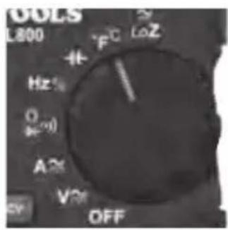
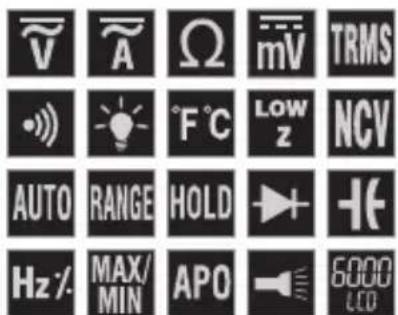
SYMBOLS ON THE METER
| ~ | AC | ≈ | AC/DC |
| Ω | Resistance (in ohms) Audible continuity | ||
| □ | Double-insulated Class II Ground | + | |
| ▶ | Diode Capacitance | + | |
| Hz | Frequency | % | Duty cycle |
| °F/°C | Temperature (Fahrenheit /Celsius) | LoZ | Low impedance |
V Voltage (volts) A Amperage (amps)
| Warning or cautionTo ensure the safe operation and service of this meter, follow all warnings and instructions detailed in this manual. |
| Risk of electric shockImproper use of this meter can lead to risk of electric shock. Follow all warnings and instructions detailed in this manual. |
| Risk of electric shockApplication around, and removal from, UNINSULATED HAZARDOUS LIVE conductors is permitted. |
SYMBOLS ON THE LCD
| ~ | AC measurement | --- | DC measurement |
| - | Negative reading Data hold | H | |
| AUTO | Auto-ranging MAX Maximum value hold | ||
| MIN | Minimum value hold Low battery | + | |
| G | Auto power off Audible continuity | • | |
| ▶ | Diode test | k | kilo (value × 103) |
| M | Mega (value × 106) | m | mili (value × 103) |
| μ | micro (value × 10-6) | n | nano (value × 10-9) |
| Ω | Ohms | V | Volts |
| A | Amps | F | Farads |
| Hz | Frequency (hertz) | % | Duty cycle |
| °F | Degrees (Fahrenheit) | °C | Degrees (Celsius) |
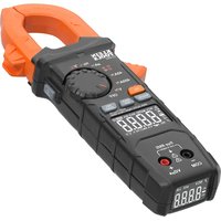
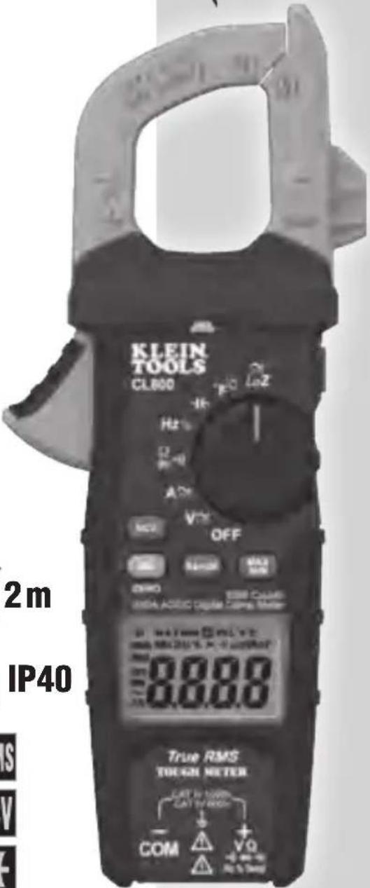
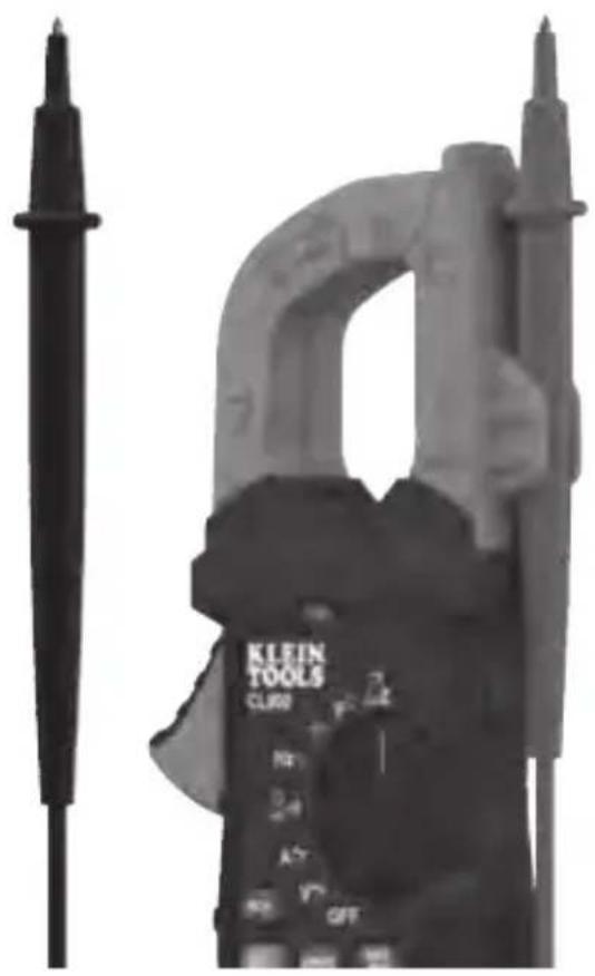
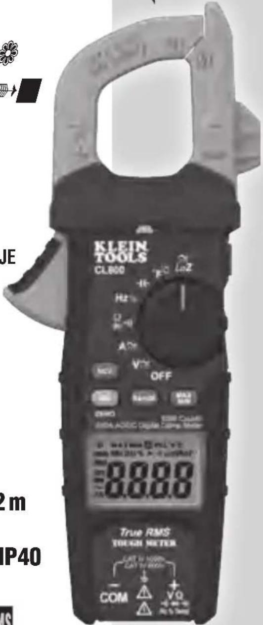
FEATURE DETAILS
NOTE: There are no user-serviceable parts inside the meter.
- 6,000 count LCD display
- Function selector switch
- Clamp
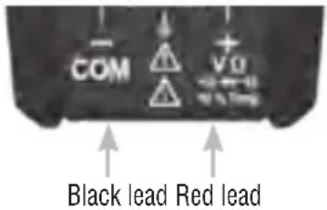
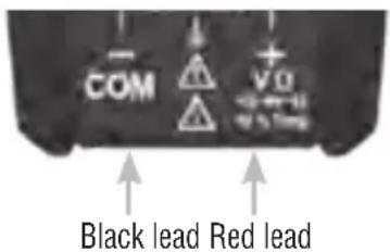
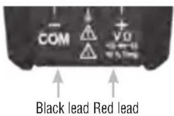
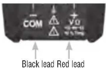
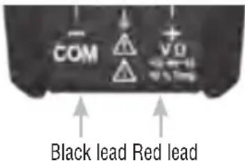
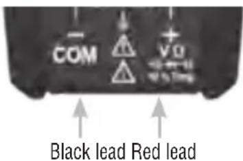
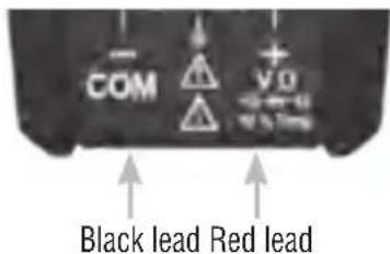
- 'COM' jack
- 'VΩ' jack
- Data hold/Backlight/Work-light button
-
'RANGE' button
-
'MAX/MIN' button
-
'SEL' (select) button
-
Clamp trigger (press to open clamp)
- Arrow markings
- Non-contact voltage testing button
- Test lead holder for test probe
- Non-contact voltage testing sensor
- Polarity markings (for DC current)
- Work light
FUNCTION BUTTONS
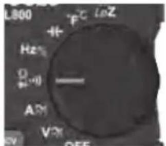
ON/OFF
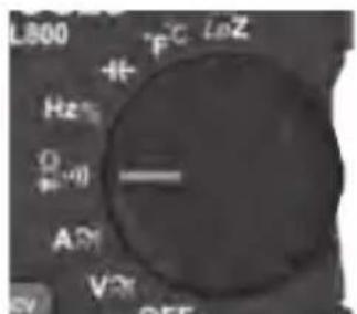
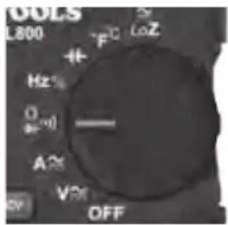
To switch the meter ON, rotate the Function selector switch 2 from the OFF setting to any measurement setting. To switch the meter OFF, rotate the Function selector switch 2 to the OFF setting. By default, the meter will automatically switch itself OFF after 30 minutes of inactivity. If the meter automatically switches itself OFF while in a measurement setting, rotate the Function selector switch 2 to any other setting (excluding the OFF setting) to switch the meter ON. To deactivate the OFF switch functionality, press and hold the 'SEL' button 9 before switching ON from the OFF setting. When auto power OFF is deactivated, the Auto power off icon will not be visible in the display.
'SEL' (SELECT) BUTTON (FOR SECONDARY FUNCTIONS)
The 'SEL' button ⑨ activates the secondary function for each application accessible by the Function selector switch ②. For current, voltage and low impedance, it toggles between AC and DC. For the other functions, it switches between °F and °C, between Hz and % duty cycle, and between Continuity, Resistance and Diode test. The default function for each application is printed on the meter in white. The secondary function (or functions) for each setting is printed on the meter in orange.
DATA HOLD
Press the Data hold/Backlight/Work light button ⑥ to hold the measurement on the display. Press again to release the display to return to live measuring.
BACKLIGHT & WORK LIGHT
Press and hold the Data hold/Backlight/Work light button ⑥ for more than one second to turn the backlight and work light ON ⑯ simultaneously. The backlight and work light will both automatically switch OFF after 3 minutes of inactivity.
RANGE
The meter defaults to auto-ranging mode ^A This is mode automatically determines the most appropriate measurement range for the testing that is being conducted. To manually force the meter to measure in a different range, use the Range button ⑦.
-
Press the 'RANGE' button ⑦ to select the measurement range manually (which be deactivated on the LCD). Press the 'RANGE' button repeatedly ⑦ to cycle through the ranges available, stopping once the desired range has been reached.
-
To return to auto-ranging mode, press and hold the 'RANGE' button ⑦ for more than one second (AWID be reactivated).
FUNCTION BUTTONS
MAX/MIN
When the 'MAX/MIN' button ⑧ is pressed, the meter keeps track of the maximum and minimum values, and the difference between the maximum and minimum values, as the meter continues to take samples.
- When measuring, press the 'MAX/MIN' button ⑧ to toggle between the maximum value (MAX) and the minimum value (MIN). If a new maximum or minimum occurs, the display will update with the new value.
- Press the 'MAX/MIN' button ⑧ for more than one second to return to normal measuring mode.
NON-CONTACT VOLTAGE TESTING
Press the NCV button 12 to test for AC voltage using the integrated non-contact voltage meter. Approach the conductor under test leading with the sensing antenna 14. The meter delivers visual warning signals when AC voltage is detected.
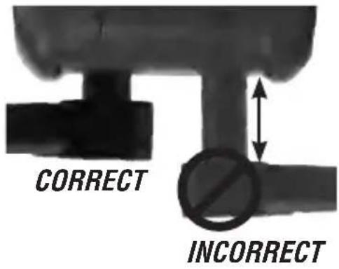
TEST LEAD HOLDER
When working with test leads, one test probe may be mounted in the test lead holder 13 to facilitate natural two-handed operation, with the clamp in one hand and a single test probe in the other.
natural_image
Close-up of a KLEIN TOOLS clamp meter with a probe and scale, no visible text or symbols on the device itself.OPERATING INSTRUCTIONS
CONNECTING TEST LEADS
Do not test if the leads are improperly seated. Results could cause intermittent display readings. To ensure a proper connection, press the leads firmly into the input jack.
TESTING IN CAT III/CAT IV MEASUREMENT LOCATIONS
Ensure that the test lead shield is pressed firmly into place. Failure to use the CATIII/CATIV shield increases the risk of arc flash.
TESTING IN CAT II MEASUREMENT LOCATIONS
CAT III/CAT IV shields may be removed for CAT II locations. This will allow testing on recessed conductors such as standard wall outlets. Take care not to lose the shields.
OPERATING INSTRUCTIONS
AC/DC CURRENT (LESS THAN 600 A)
AC current is measured by pressing the clamp trigger 10 to open the clamp 3 and placing it around a wire carrying a current. When measuring, care should be taken to ensure that the clamp is 3 completely closed, with the trigger 10 fully released, and that the wire passes perpendicularly through the centre of the clamp 3 in line with the arrow markings 11.

To measure current:
- Rotate the Function selector switch ② to the AC/DC current A ≈ setting.
NOTE: The meter defaults to AC measurement. Press the 'SEL' button ⑨ to toggle between AC and DC modes. The AC or DC icon on the LCD indicates which mode is selected.
- Place the clamp 3 around the wire. When measuring DC current, align the polarity markings 15 on the clamp with the polarity of the wire to avoid negative readings. The current measurement will be shown in the display. The meter will auto-range to display the measurement in the most appropriate range.
⚠️ Disconnect test leads when measuring with the clamp.
NOTE: If non-zero values are displayed prior to measuring in DC current mode, an offset correction is required. With the meter in DC current mode, press and hold the 'SEL' button ⑨ to activate the DC current ZERO function. Subsequent DC current measurements will automatically subtract the offset correction for improved accuracy.
OPERATING INSTRUCTIONS
AC/DC VOLTAGE (LESS THAN 1,000 V)
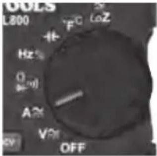
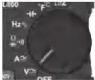
- Insert the RED test lead into the VΩ jack ⑤ and the BLACK test lead into the COM jack ④, and rotate the Function selector switch ② to the AC/DC voltage V setting. The meter defaults to AC measurement. To measure DC, press the 'SEL' button ⑨ to toggle between AC and DC modes. The AC or DC icon on the LCD indicates which mode has been selected. Note 'AC' or 'DC' on the display.
- Apply test leads to the circuit to be tested to measure the voltage. The meter will auto-range to display the measurement in the most appropriate range.
NOTE: If ‘-’ appears on the LCD, the test leads are being applied to the circuit in reverse. Change the position of the leads to correct this.
NOTE: When in a voltage setting and the test leads are open, readings of the order mV may appear on the display. This is noise and is normal. By touching the test leads together to close the circuit, the meter will measure zero volts.
AC/DC LoZ VOLTAGE (LESS THAN 600 V)
- Insert the RED test lead into the VΩ jack ⑤ and the BLACK test lead into the COM jack ④, and rotate the Function selector switch ② to the AC/DC LoZ voltage ≈ _LoZ setting. The meter defaults to AC measurement. To measure DC, press the 'SEL' button ⑨ to toggle between AC and DC modes. The AC or DC icon on the LCD indicates which mode has been selected. Note 'AC' or 'DC' on the display.
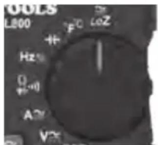
- Apply test leads to the circuit to be tested to measure the voltage. The meter will auto-range to display the measurement in the most appropriate range.

Do not attempt to measure voltages greater than 600 V in the LoZ setting.
OPERATING INSTRUCTIONS
CONTINUITY
- Insert the RED test lead into the VΩ jack ⑤ and the BLACK test lead into the COM jack ④, and rotate the Function selector switch ② to the Continuity/Resistance/Diode test setting.
NOTE: The meter will default to continuity testing in this mode. Ensure that the Continuity testing icon is visible on the display. If not, press the 'SEL' button ⑨ repeatedly until the icon is shown.
- Stop the power to the circuit.
- Test for continuity by connecting the conductor or circuit with test leads. If resistance is measured at less than 50 Ω, an audible signal will sound and the display will show a resistance value indicating continuity. If the circuit is open, the display will show 'OL'.
⚠️ DO NOT attempt to measure continuity on a live circuit.
RESISTANCE MEASUREMENTS
- Insert the RED test lead into the VΩ jack ⑤ and the BLACK test lead into the COM jack ④, and rotate the Function selector switch ② to the Continuity/Resistance/Diode test setting.
NOTE: The meter will default to continuity testing in this mode. Press the 'SEL' button ⑨ once to enter Resistance testing mode. The Resistance icon Ω will appear on the display.
- Stop the power to the circuit.
- Measure resistance by connecting the test leads to the circuit. The meter will auto-range to display the measurement in the most appropriate range.
NOTE: When in the Resistance setting and the test leads are open (not connected across a resistor), or when a failed resistor is under test, the display will indicate OL. This is normal.
⚠️ DO NOT attempt to measure resistance on a live circuit.
OPERATING INSTRUCTIONS
DIODE TEST
- Insert the RED test lead into the VΩ jack ⑤ and the BLACK test lead into the COM jack ④, and rotate the Function selector switch ② to the Continuity/Resistance/Diode test setting.
NOTE: The meter will default to continuity testing in this mode. Press the 'SEL' button ⑨ twice to enter Diode testing mode. The Diode icon ➤ will appear on the display.
- Touch the test leads to the diode. A reading of 200-800 mV on the display indicates forward bias. 'OL' indicates reverse bias. An open device will show 'OL' in both polarities. A shorted device will show approximately 0 mV.
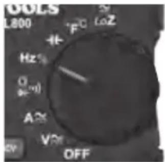
FREQUENCY/DUTY CYCLE
- Insert the RED test lead into the VΩ jack ⑤ and the BLACK test lead into the COM jack ④, and rotate the Function selector switch ② to the Frequency/Duty cycle H setting.
NOTE: The meter will default to frequency testing in this mode. To enter Duty-cycle testing mode, press the 'SEL' button ⑨ once. Ensure that the appropriate icon (either Hz or %) appears on the display.
- Measure by connecting the test leads across the circuit.
CAPACITANCE
- Insert the RED test lead into the VΩ jack ⑤ and the BLACK test lead into the COM jack ④, and rotate the Function selector switch ② to the Capacitance setting.
OPERATING INSTRUCTIONS
- Stop the power to the circuit.
- Measure the capacitance by connecting test leads across the capacitor. The meter will auto-range to display the measurement in the most appropriate range.
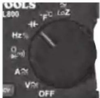
TEMPERATURE
- Insert the K-type thermocouple into the VΩ ⑤ and COM ④ jacks (observe polarity markings on the thermocouple and meter), and rotate the Function selector switch ② to the Temperature °F °C setting.
NOTE: The meter will default to the Fahrenheit scale in this mode. To enter the Celsius scale, press the 'SEL' button ⑨ once. Ensure that the appropriate icon (either °F or °C) appears on the display.
NOTE: The meter may be set to default to the Celsius scale by switching the meter ON from the OFF position with the Data hold & Backlight button 6 depressed. To reset the default to the Fahrenheit scale, repeat the switching-on sequence.
2. To measure the temperature, make contact between the thermocouple tip and the object being measured. When the thermocouple tip and object are in thermal equilibrium, the measurement on the display will stabilise. The meter will auto-range to display the measurement in the most appropriate range.
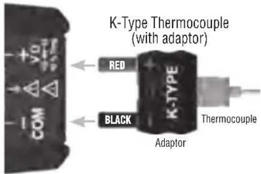
⚠️ Remove the thermocouple before switching the meter to other measurement functions.
The thermocouple included with the original purchase is suitable for temperatures below 356^ F/180°C only. Tomeasure higher temperatures, a K-type thermocouple with the appropriate measurement range should be used.
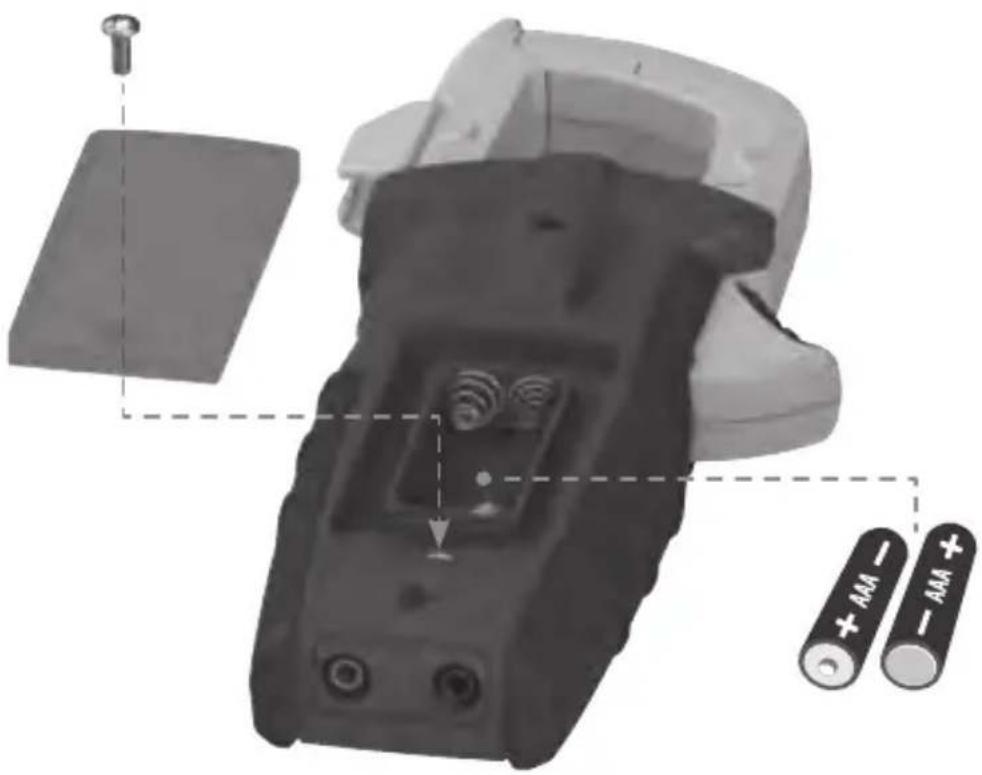
MAINTENANCE
BATTERY REPLACEMENT
When the indicator is displayed on the LCD, the batteries must be replaced.
- Remove the screw from the battery door.
- Replace the 2 × AAA batteries (note the proper polarity).
- Replace the battery door and fasten it securely with the screw.
natural_image
Close-up of a handheld electronic device with battery pack and two batteries labeled + and - (no text or symbols on main body)To avoid the risk of electric shock, disconnect leads from any voltage source before removing the battery door.
To avoid the risk of electric shock, do not operate the meter after the battery door has been removed.
CLEANING
Make sure that the meter is switched off and then wipe it with a clean, dry, lint-free cloth. Do not use abrasive cleaners or solvents.
STORAGE
Remove the batteries when the meter is not in use for a prolonged period of time. Do not expose to high temperatures or humidity. After a period of storage in extreme conditions exceeding the limits mentioned in the General specifications section, allow the meter to return to normal operating conditions before using.
WARRANTY
Do not place the equipment and its accessories into a domestic rubbish bin. Items must be properly disposed of in accordance with local regulations.
CUSTOMER SERVICE
KLEIN TOOLS, INC.
450 Bond Street
Lincolnshire, IL 60069, USA
international@kleintools.com
www.kleintools.com
DEUTSCH
CL800E
TOUGH METER
CE

Intertek
4007177

SYMBOLE AUF DEM MESSGERÄT
natural_image
Close-up of a KLEIN TOOLS clamp meter with a probe and scale (no visible text or symbols on the device itself)GEBRAUCHSANLEITUNG
TEMPERATUR
natural_image
Exploded view of a battery pack assembly with two batteries and a screwdriver (no text or symbols visible)

TOUGH METER
CE

Intertek
4007177

SPÉCIFICATIONS GÉNÉRALES
MAINTIEN DES DONNÉES
natural_image
Close-up of a KLEIN TOOLS clamp meter with a probe and scale, no visible text or symbols on the device itself.INSTRUCTIONS D'UTILISATION
CONNEXION DES FILS DE TEST
natural_image
3D mechanical component diagram showing internal components and battery arrangement (no text or symbols)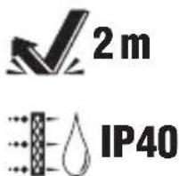
KLEIN TOOLS

TOUGH METER
CE

Intertek
4007177

natural_image
Close-up of a KLEIN TOOLS CLABO clamp meter with a vertical probe and base (no visible text or symbols on the device itself)INSTRUCCIONES DE USO