CL490 - Measuring equipment Klein Tools - Free user manual and instructions
Find the device manual for free CL490 Klein Tools in PDF.


User questions about CL490 Klein Tools
0 question about this device. Answer the ones you know or ask your own.
Ask a new question about this device
Download the instructions for your Measuring equipment in PDF format for free! Find your manual CL490 - Klein Tools and take your electronic device back in hand. On this page are published all the documents necessary for the use of your device. CL490 by Klein Tools.
USER MANUAL CL490 Klein Tools
text_image
AC =8.0.0.8 DC +1A -1ACEUKCA

Intertek
5001748
CAT III
600V
GENERAL SPECIFICATIONS
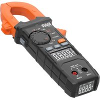
Klein Tools CL490 is an auto-ranging true root mean square (TRMS) digital clamp meter that measures AC/DC current via the clamp, AC/DC voltage, DC microamps, resistance, continuity, frequency, capacitance, tests diodes via test-leads, and temperature via a thermocouple probe. It features high visibility, reverse contrast transflective LCD main and secondary displays that optimize viewability in dark or bright ambient environments.
- Environment: Indoor. DO NOT expose to moisture, rain, or snow.
- Operating Altitude: 6562 ft. (2000m)
• Relative Humidity: <75% non-condensing
- Operating Temp: 32^ to 122^ F (0° to 50°C)
• Storage Temp: 14° to 122°F (-10° to 50°C)
• Accuracy: Values stated at 65° to 83°F (18° to 28°C)
- Temp Coefficient: 0.1 x (Quoted Accuracy) per °C above 28°C or below 18°C, corrections are required when ambient working temp is outside of Accuracy Temp range
- Dimensions: 8.46" x 3.54" x 1.50" (215 x 90 x 38 mm)
• Weight: 12.20 oz. (346 g) including batteries
• Calibration: Accurate for one year
• Auto Power-Off (APO): After approx. 5 minutes of inactivity
• Standards: IEC EN 61010-1, 61010-2-032. IEC EN 61326-1, 61326-2-2.
Conforms to UL STD.61010-1, 61010-2-032; Certified to CSA STD.C22.2 NO. 61010-1, 61010-2-032.
- Pollution degree: 2
- Accuracy: ± (% of reading + # of least significant digits)
- Drop Protection: 6.6 ft. (2m)
- Safety Rating: CATIII 600V, Class 2, Double insulation
CAT III: Measurement category III is applicable to test and measuring circuits connected to the distribution part of the building's low-voltage MAINS installation.
- Electromagnetic Environment: IEC EN 61326-1. This equipment meets requirements for use in basic and controlled electromagnetic environments like residential properties, business premises, and light-industrial locations.
Specifications subject to change.
ELECTRICAL SPECIFICATIONS
| Function Range Resolution Accuracy | |||
| AC Voltage (V AC) | 400.0mV 0.1 | mV ±(1.8% + 5 digits) | |
| 4.000V 0.00 | 1V ±(1.5% + 5 digits) | ||
| 40.00V 0.01 | V | ±(1.2% + 5 digits) | |
| 400.0V 0.1V | |||
| 600V 1V ±(1.5% + 5 digits) | |||
| DC Voltage (V DC) | 400.0mV 0.1 | mV ±(1.0% + 8 digits) | |
| 4.000V 0.00 | 1V | ±(0.8% + 3 digits)40. | |
| 400.0V 0.1V | |||
| 600V 1V ±(1.0% + 3 digits) | |||
Input Impedance: \~10MΩ
Frequency Range: 45 to 400Hz
Maximum Input: 600V AC RMS or 600V DC
| AC Current (A AC) | 40.00A 0.01A | ±(2.0% + 9 digits) |
| 400.0A 0.1A | ||
| DC Current (A DC) | 40.00A 0.01A | ±(2.0% + 9 digits) |
| 400.0A 0.1A |
Frequency Range: 50 to 60Hz
Minimum Current Measurable: 0.3A AC or DC
| DCMicroamps(μA DC) | 200.0μA 0.1 | μA ±(1.0% + 5 digits) |
Maximum Input: 600V AC RMS or 600V DC
| Resistance | 400.0Ω 0.1Ω ±(1.2% + 5 digits) | ||
| 4.000kΩ | 0.001kΩ | ±(1.2% + 3 digits) | |
| 40.00kΩ 0.01kΩ | |||
| 400.0kΩ 0.1kΩ | |||
| 4.000MΩ 0.001MΩ | |||
| 40.00MΩ 0.01MΩ ±(2.0% + 5 digits) | |||
Maximum Input: 600V AC RMS or 600V DC
ELECTRICAL SPECIFICATIONS
| Function Range Resolution Accuracy | |||
| Capacitance | 40.00nF 0.01 nF ±(4.0% + 25 digits) | ||
| 400.0nF 0.1nF | ±(4.0% + 8 digits) | ||
| 4.000μF 0.001μF | |||
| 40.00μF 0.01μF | |||
| 400.0μF 0.1μF | |||
| 4.000mF 0.001mF ±(5.0% + 9 digits) | |||
Maximum Input: 600V AC RMS or 600V DC
| Temperature °F | -40° to 10°F | 1°F | ±(1.2% + 7 digits) |
| >10° to 1832°F | ±(1.2% + 6 digits) | ||
| Temperature °C | -40° to -12°C | 1°C | ±(1.2% + 4 digits) |
| >-12° to 1000°C | ±(1.2% + 3 digits) |
Maximum Input: 600V AC RMS or 600V DC
| Frequency | 10Hz to 60kHz | 0.001Hz to 0.01kHz | ±(0.1% + 5 digits) |
| Duty Cycle | 0.1% to 99.9% ≤10kHz | 0.1% | ±1.5%(Range: 10% – 90%) |
Maximum Input: 600V AC RMS or 600V DC
Voltage Range: 8V to 240V AC RMS
Pulse Width: >0.1ms, must be zero-crossing signal.
OTHER MEASUREMENT APPLICATIONS
Maximum Input: 600V AC RMS or 600V DC
- Diode Test: Approx. 1mA, open circuit voltage \~3.0V DC
- Continuity Check: Audible signal < 10 , max current 1.5mA
• Sampling Frequency: 3 samples per second - Auto Power off: After \~5 minutes of inactivity.
• Over Limit: "OL" indicated on display - Polarity: "-" on display indicates negative polarity
• Display: 3-3/4 digit, 4000 Count LCD
⚠️ WARNINGS
To ensure safe operation and service of the meter, follow these instructions. Failure to observe these warnings can result in severe injury or death.
- Before each use verify meter operation by measuring a known voltage or current.
⚠️ WARNINGS - GENERAL
- Never use the meter on a circuit with voltages that exceed the category based rating of this meter.
- DO NOT use the meter during electrical storms or in wet weather.
- DO NOT use the meter or test leads if they appear to be damaged.
- Use only with CAT III or CAT IV rated test leads. Probe assemblies to be used for MAINS measurements shall meet IEC/EN 61010-031 with a voltage RATING of CAT IV 600V or better.
- Ensure test leads are fully seated into jacks, and keep fingers away from the metal probe contacts when making measurements.
- Use caution when working with voltages above 25V AC RMS or 60V DC. Such voltages pose a shock hazard.
- To avoid false readings that can lead to electrical shock, replace batteries when a low battery indicator appears.
- DO NOT attempt to measure resistance or continuity on a live circuit.
- Always adhere to local and national safety codes. Use personal protective equipment to prevent shock and arc blast injury where hazardous live conductors are exposed.
- To avoid risk of electric shock, disconnect leads from any voltage source before removing battery door.
- To avoid risk of electric shock, do not operate meter while battery door is removed.
⚠️ WARNINGS - NCV FUNCTION
- Before and after each use of the NCVT, verify operation by testing a known working circuit that is within the rating of this unit.
- Never assume neutral or ground wires are de-energized. Neutrals in multi-wire branch circuits may be energized when disconnected and must be retested before handling.
• The NCV tester WILL NOT detect voltage if:
• The wire is shielded.
- The operator is not grounded or is otherwise isolated from an effective earth ground.
- The voltage is DC.
• The NCV tester MAY NOT detect voltage if:
• The user is not holding the tester.
- The user is insulated from the tester with a glove or other materials.
• The wire is partially buried or in a grounded metal conduit.
• The tester is at a distance from the voltage source.
- The field created by the voltage source is blocked, dampened, or otherwise interfered with.
- The frequency of the voltage is not a perfect sine wave between 50 and 60Hz.
• The tester is outside of operation conditions (listed in Specifications section).
- Operation may be affected by differences in socket design and insulation thickness and type; tester may not be compatible with some types of standard or tamper resistant (TR) electrical outlets.
- DO NOT apply to uninsulated hazardous live conductors.
- Detection above 50V is specified under “normal” conditions as specified below. The tester may detect at a different threshold at different conditions, or may not detect at all unless:
- The tip of the tester is within 0.25" of an AC voltage source radiating unimpeded.
• The user is holding the body of the tester with his or her bare hand.
• The user is standing on or connected to earth ground.
• The air humidity is nominal (50% relative humidity).
• The tester is held still.
SYMBOLS ON METER

AC/DC Current or Voltage Resistance (OKms)
NCV
Non-Contact Voltage Tester Audible Continuity

Double Insulated Class II

DC Microamps

Warning or Caution

Risk of Electrical Shock

Suitable for Uninsulated Hazardous Live Conductors

Read Instructions

Diode

Capacitance

Frequency

Duty Cycle V Voltage (Volts)
A Amperage (Amps) Backlight Brightness


Temperature (Fahrenheit / Celsius)

Select

Positive

Negative

Common Ground


Power Off

Maximum/Minimum Value
SYMBOLS ON LCD

(Alternating Current)
DC (Direct C)

Negative Reading Data Hold

Auto Ranging Diode

Farrads Auto Power Off

Non-Contact Voltage Tester Audible C

Low Battery

Degrees (Fahrenheit)

Mega (value x 10 ^6 )

milli (value x 10 ^-3 )

nano (value x 10 ^9 )

Amps

Frequency/Duty Cycle

Maximum Value Hold
MAX-MIN
Difference between MAX and MIN values


ZERO
REL
MIN

Degrees (Celsius)
kilo (value x 10³)
micro (value x 10 ^-6 )
Volts
Ohms
DC Current Zero Function
Relative Mode
Minimum Value Hold
Hazardous Voltage Indicator
FEATURE DETAILS
text_image
KLEIN TOOLS CLAMP 1 2 3 4 5 6 7 8 9 10 11 12 13 14 15 16 17 18 OFF MAX MAX MAX MAX MAX MAX MAX MAX MAX MAX MAX MAX MAX MAX MAX MAX MAX MAX MAX MAX MAX MAX MAX MAX MAX MAX MAX MAX MAX MAX MAX MAX MAX MAX MAX MAX MAX MAX MAX MAX MAX MAX MAX MAX MAX MAX MAX MAX MAX MAX Max Max Max Max Max Max Max Max Max Max Max Max Max Max Max Max Max Max Max Max Max Max Max MaxFEATURE DETAILS
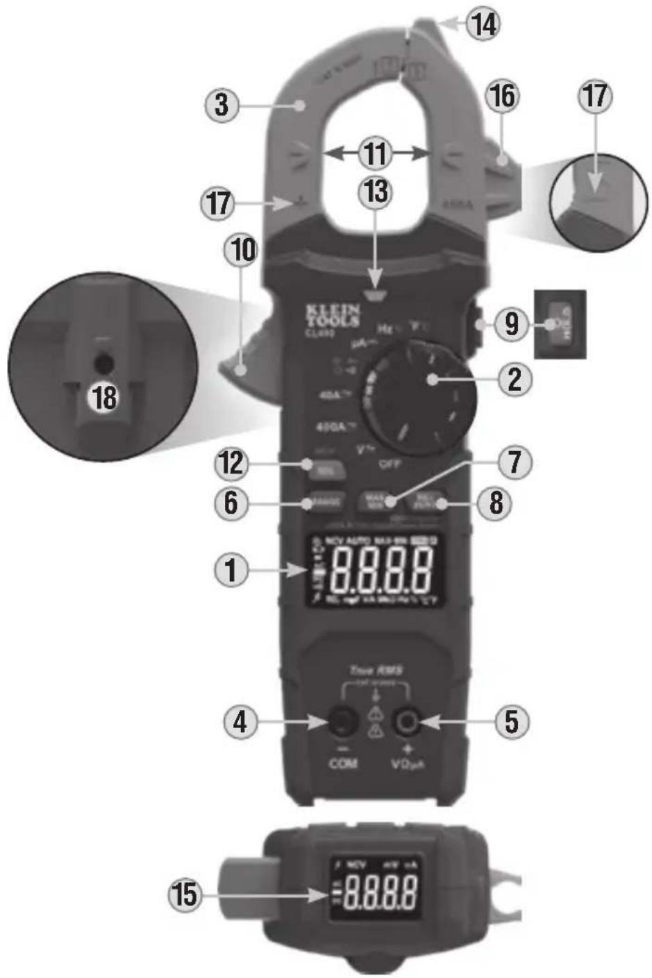
- 4000 count LCD display
- Function Selector Switch
- Clamp
- "COM" Jack
- "VΩμA" Jack
- "RANGE" Button
- "MAX/MIN" Button
- "REL/ZERO" Button
-
"HOLD"/Brightness Button
-
Clamp Trigger
- Arrow Markings
- "SEL/NCV" Button
- NCV Indicator
- NCV Sensing Antenna
- Secondary LCD Display
- Test Lead Holder
- Polarity Markings (on front and back)
- Magnet Mount (on back)
FUNCTION BUTTONS
ON/OFF
To power ON the meter, rotate the Function Selector Switch 2 from the OFF setting to any measurement setting. To power OFF the meter, rotate the Function Selector Switch 2 to the OFF setting. The Auto-Power Off icon will be visible on the display. By default, the meter will automatically power OFF after 5 minutes of inactivity. If the meter automatically powers-OFF while in a measurement setting, press any button to power the meter ON, or rotate Function Selector Switch 2 switch to OFF, then power ON the meter. To deactivate Auto-Power OFF functionality press and hold the "SEL/NCV" Button 12 before powering ON from the OFF setting. When Auto-Power OFF is deactivated, the Auto-Power Off icon will not be visible on the display.
NOTE: Auto Power-OFF is activated by default and must be deactivated each time the meter is powered ON.
"SEL/NCV" BUTTON (FOR SECONDARY FUNCTIONS)
Pushing the "SEL/NCV" Button 12 activates the secondary function for each application accessible by the Function Selector Switch 2. For voltage and current (excluding DC uA), it toggles between AC and DC. For the other functions, it switches between °F and °C, between Hz and % Duty-cycle, and between Continuity, Resistance, Capacitance and Diode-Test. The default function for each application is printed on the meter in white; the secondary function or functions for each setting is printed on the meter in orange.
"SEL/NCV" BUTTON (FOR NCV TESTING)
Press and hold the "SEL/NCV" Button 12 to enter Non-contact Voltage Testing (NCV) mode to test for presence of AC voltage. The NCV icon and "EF" will be present on the display. Approach the conductor under test leading with the sensing antenna 14. In the presence of AC voltage, the red NCV light 13 will flash, audible signals (beeps) will sound, and dashes will appear on the display. As the NCV sensing antenna 14 approaches the voltage source, more dashes will be presented on the display and the frequency of the audible sound will increase. Release the "SEL/NCV" Button 12 to exit NCV testing mode.
NOTE: When NCV Function is initiated, a blinking or steady red glow and an audible beep indicate voltage present and the screen will display the corresponding sensitivity level (1 to 4 bars) when voltage is detected. If no indication, voltage could still be present.
NOTE: Only voltages of 40V AC or greater will be detected.
Press the "HOLD"/Brightness Button ⑨ to hold the measurement on the display. Press again to release the display and return to live measuring.
Press and hold the "HOLD"/Brightness Button 9 to toggle between high and low brightness for the backlight on the main display. By default, the meter will use the low brightness setting on both the main and secondary displays.
FUNCTION BUTTONS
RANGE
The meter defaults to auto-ranging mode. This mode automatically determines the most appropriate measurement range for the testing that is being conducted. The icon will be visible on the display. To manually force the meter to measure in a different range, use the "RANGE" Button 6.
- Press the "RANGE" Button 6 to manually select measurement range (A is deactivated on the LCD). Repeatedly press the "RANGE" Button 6 to cycle through the available ranges, stopping once the desired range is reached.
- To return to auto-ranging mode, press and hold the "RANGE" Button 6 for more than two seconds (A is reactivated).
MAX/MIN
The "MAX/MIN" function can be used when measuring with voltage, current, resistance, temperature, and DC A functions. When the "MAX/MIN" Button ⑦ is pressed, the meter keeps track of the Maximum and Minimum values, and the difference between the Maximum and Minimum values while continuing to take samples.
- When measuring, press "MAX/MIN" Button ⑦ to toggle between the Maximum value (MAX), the Minimum value (MIN), and the difference between Maximum and Minimum (MAX-MIN) values. "MAX", "MIN", or "MAX-MIN" will appear on the display, indicating the value being shown. If a new maximum or minimum occurs the display updates with that new value.
- Press "MAX/MIN" Button ⑦ for more than two seconds to return to normal measuring mode.
RELATIVE MODE
REL Measurement: Press the "REL/ZERO" Button 8 to initiate measurement relative to the current reading. The REL icon will be present on the display. Subsequent measurements are displayed relative to the original measurement. (Applies to AC/DC Voltage, AC Current, Resistance, Capacitance, DC μA, and Temperature). Press "REL/ZERO" 8 again to exit relative mode.
DC ZERO Function: When measuring DC current with the clamp, press the "REL/ZERO" Button 8 to activate the DC current zero function. This will set the display to zero by subtracting the current value as an offset. The ZERO icon will be present on the display. Press the "REL/ZERO" Button 8 again to exit DC current zero mode.
NOTE: If the DC current range changes, the DC current ZERO function procedure must be repeated.
OPERATING INSTRUCTIONS
CONNECTING TEST LEADS
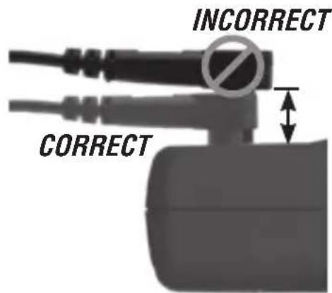
DO NOT test if leads are improperly seated. Results could cause intermittent display readings. To ensure proper connection, firmly press leads into the input jack completely.
text_image
INCORRECT CORRECTTESTING IN CAT III MEASUREMENT LOCATIONS
Ensure the test lead shield is pressed firmly in place. Failure to use the CATIII / CATIV shield increases arc-flash risk.
text_image
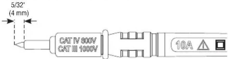
5/32" (4 mm) CAT IV 800V CAT III 1000V 10ATESTING IN CAT II MEASUREMENT LOCATIONS
CAT III / CAT IV shields may be removed for CAT II locations. This will allow testing on recessed conductors such as standard wall outlets. Take care not to lose the shields.

text_image
CAT IV 800V CAT III 1000V 0.7" (18 mm)AC/DC CURRENT (LESS THAN 400A)
Current is measured by pressing the clamp trigger 10 to open the clamp and placing it around a current-carrying wire. When measuring, care should be taken to ensure that the clamp is completely closed with trigger 10 fully released, and that the wire passes perpendicularly through the center of the clamp in line with the arrow markings 11.
NOTE: Current measurement can be made by clamping around single conductors, but not cables containing both live and neutral wires. In this case, a line splitter is required (Klein Tools Cat. No. 69409 recommended).
LIVE CABLE
NEUTRAL WIRE GROUND WIRE HOT WIRE
OPERATING INSTRUCTIONS
To measure current:
-
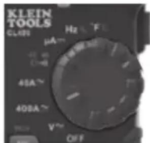
Rotate the Function Selector Switch ② to the 400A setting. NOTE: When measuring DC current, align the polarity markings ⑰ on the clamp with the polarity of the wire to avoid negative readings.
-
Place clamp around wire. The current measurement will be shown on the display.
text_image
KLEIN TOOLS CLAB Hz F µA 45A 408A V OFFNOTE: The meter defaults to AC measurement. Press the "SEL/NCV" Button 12 to toggle between AC and DC modes. The AC or DC icon on the display indicates which mode is selected.
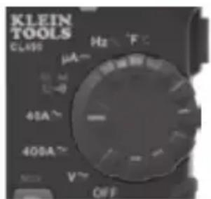
NOTE: If the measurement is less than 40A, rotate the Function Selector Switch ② to the 40A setting for improved resolution.
text_image
KLEIN TOOLS CL99 μA Hz F 45A 400A V OFFNOTE: If non-zero values are displayed prior to measuring in DC current mode, a DC zero offset correction is required. With meter in DC current mode, press the "REL/ZERO" Button 8 to activate the DC current ZERO function. ZERO icon will be present on the display. Subsequent DC current measurements automatically subtract the offset correction for improved accuracy. Press "REL/ZERO" Button 8 to return to normal measuring mode.
NOTE: DO NOT use DC current function if the Magnetic Hanger accessory is attached to the back of the meter. Interferences from the magnet can lead to inaccurate measurements.
⚠️ Disconnect test leads when measuring with the clamp.
OPERATING INSTRUCTIONS
AC/DC VOLTAGE (LESS THAN 600V)
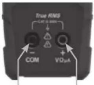
- Insert RED test lead into VΩμA jack ⑤, and BLACK test lead into COM jack ④, and rotate Function Selector Switch ② to the V setting for AC or DC measurements. The meter defaults to AC measurement. To measure DC, press the "SEL/NCV" button ⑫ to toggle between AC and DC modes. The AC or DC icon on the LCD indicates which mode is selected.
text_image
True RMS CAT 6.8 MHz COM VΩμA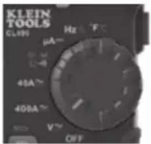
text_image
KLEIN TOOLS CL499 μA- 45A 400A V OFF Hz F°CRed leadBlack lead
- Apply test leads to the circuit to be tested to measure voltage. The meter will auto-range to display the measurement in the most appropriate range.
NOTE: If “-” appears on the LCD, this indicates negative polarity for DC voltage. Swap the positions of the leads to correct this.
NOTE: When in a voltage setting and the test leads are open, readings of order mV may appear on the display. This is noise and is normal. By touching the test leads together to close the circuit the meter will measure zero volts.
NOTE: To access mV range for AC V or DC V..., the "RANGE" Button ⑥ must be used.
Manual Mode Sequence
| First Press | Second Press | Third Press | Fourth Press | Fifth Press | |
| AC Range | 0-600V 0-4 | 400.0V 0-4 | 0.00V 0-4 | 000V 0-400.0 | mV |
| DC Range | 0-40.00V 0-4 | 400.0V 0-4 | 600V 0-4 | 0.0mV 0-4 | 000V |
NOTE: When voltages in excess of 25V AC or 60V DC are measured the hazardous voltage indicator will be present on the display.
OPERATING INSTRUCTIONS
CONTINUITY
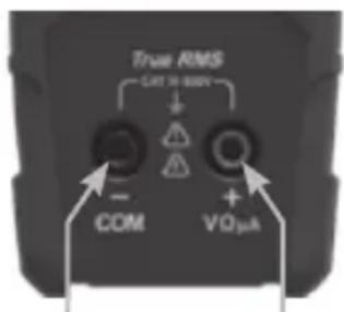
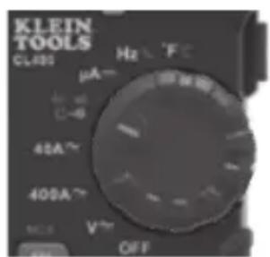
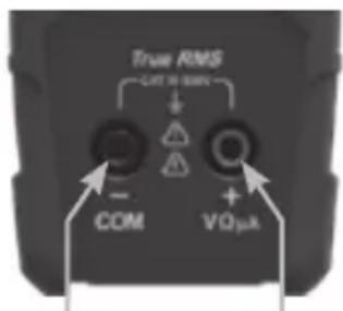
- Insert RED test lead into VΩμA jack 5, and BLACK test lead into COM jack 4, and rotate Function Selector Switch 2 to the Continuity/Resistance/Capacitance/Diode-Test setting.
NOTE: The meter defaults to Continuity testing in this mode. Ensure that the Continuity Testing icon is visible on the display. If not, press the "SEL/NCV" Button 12 repeatedly until the icon is shown. - Remove power from circuit.
- Test for continuity by connecting conductor or circuit with test leads. If resistance is measured less than 10 , an audible signal will sound and display will show a resistance value indicating continuity. If circuit is open, display will show "OL".
text_image
True RMS Cut to screen - COM VOμARed leadBlack lead
text_image
KLEIN TOOLS CLABS μA- C-0 45A~ 400A~ MOS V~ OFF
DO NOT attempt to measure continuity on a live circuit.
RESISTANCE MEASUREMENTS
- Insert RED test lead into VΩμA jack ⑤, and BLACK test lead into COM jack ④, and rotate Function Selector Switch ② to the Continuity/Resistance/Capacitance/Diode-Test setting.
NOTE: The meter defaults to Continuity testing in this mode. Press the "SEL/NCV" Button 12 until the resistance icon Ω appears on the display. - Remove power from circuit.
- Measure resistance by connecting test leads to circuit. The meter will auto-range to display the measurement in the most appropriate range.
text_image
True RMS OUT 30 MIN - COM VQμkRed leadBlack lead
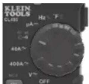
text_image
KLEIN TOOLS CLABS μA Hz F 40A 400A V OFFNOTE: When in a Resistance setting and the test leads are open (not connected across a resistor), or when a failed resistor is under test, the display will indicate "OL". This is normal.

DO NOT attempt to measure resistance on a live circuit.
OPERATING INSTRUCTIONS
CAPACITANCE
- Insert RED test lead into VΩμA jack 5, and BLACK test lead into COM jack 4, and rotate Function Selector Switch 2 to the Continuity/Resistance/Capacitance/Diode-Test setting.
NOTE: The meter defaults to Continuity testing in this mode. To measure capacitance, press the "SEL/NCV" Button 12 until nF appears on the display.
-
Remove power from circuit.
-
Measure capacitance by connecting test leads across the capacitor. The meter will auto-range to display the measurement in the most appropriate range.
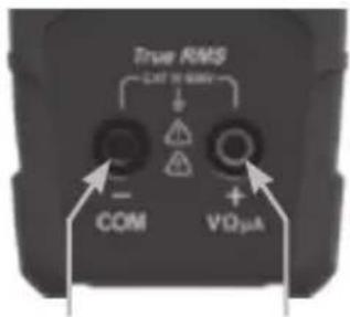
text_image
True RMS EXT 100V COM VIOμARed leadBlack lead
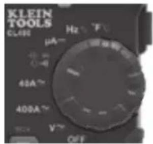
text_image
KLEIN TOOLS CLAB μA- 45A 400A Hz T OFFDIODE TEST
- Insert RED test lead into VΩμA jack 5, and BLACK test lead into COM jack 4, and rotate Function Selector Switch 2 to the Continuity/Resistance/Capacitance/Diode-Test # setting.
NOTE: The meter defaults to Continuity testing in this mode. Press the "SEL/NCV" Button 12 until the diode icon appears on the display. Touch test leads to diode. A reading of 200-800mV on display indicates forward bias, "OL" indicates reverse bias. An open device will show "OL" in both polarities. A shorted device will show approximately 0mV.
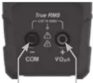
text_image
True RMS CAT W/NDY + COM VΩμARed leadBlack lead
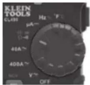
text_image
KLEIN TOOLS CLAB μA- 41A~ 400A~ Hz F OFFμA DC CURRENT (LESS THAN 200 μA)
-
Insert RED test lead into VΩμA jack 5, and BLACK test lead into COM jack 4, and rotate Function Selector Switch 2 to the DC μA setting. The "μA" and "DC" icons will appear on the display.
-
Remove power from circuit and open circuit at measurement point.
-
Connect test leads in series with the circuit.
-
Apply power to the circuit to take the measurement.
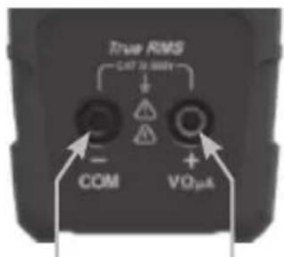
text_image
True RMS OUT 0 MHz COM VO2μA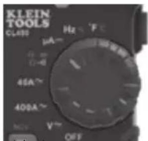
text_image
KLEIN TOOLS CLASS μA~ Ω-6 45A~ 400A~ MCV V~ OFF⚠ DO NOT attempt to measure more than 200μA.
Red leadBlack lead
FREQUENCY / DUTY-CYCLE
- Insert RED test lead into VΩμA jack ⑤ and BLACK test lead into COM jack ④, and rotate Function Selector Switch ② to the Frequency/Duty-Cycle Hsetting.
NOTE: The meter defaults to Frequency testing in this mode. To enter Duty-Cycle testing mode, press the "SEL/NCV" Button 12 once. Ensure that the appropriate icon (either Hz or %) appears on the display.
- Measure by connecting test leads across the circuit.
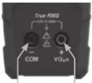
text_image
True RMS CAT 2 MIN - COM VO2mARed leadBlack lead
text_image
KLEIN TOOLS CLABS Hz F μA- 10 mA C-θ 40A~ 400A~ R/W V~ OFFTEMPERATURE
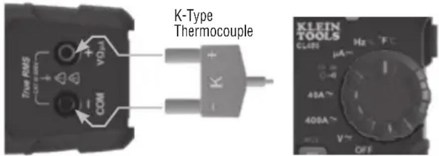
- Insert thermocouple into the VΩμA ⑤ and COM ④ jacks (observe polarity markings on thermocouple and meter), and rotate Function Selector Switch ② to the Temperature °F setting.
NOTE: The meter defaults to Fahrenheit scale in this mode. To enter Celsius scale, press the "SEL/NCV" Button 12 once. Ensure that the appropriate icon (either °F or °C) appears on the display.
- To measure temperature, make contact between the thermocouple tip and the object being measured. When thermocouple tip and object are in thermal equilibrium, the measurement on the display will stabilize.
text_image
K-Type Thermocouple True RMS COM VOL COM K KLEIN TOOLS CLAS μA Hz FC 41A 409A V~ OFF⚠️ Remove thermocouple before switching meter to other measurement functions.
The thermocouple included with the original purchase is suitable for temperatures below 482^ F/ 250^ C only. To measure higher temperatures, a K-type thermocouple with the appropriate measurement range should be used.
MAINTENANCE
BATTERY REPLACEMENT
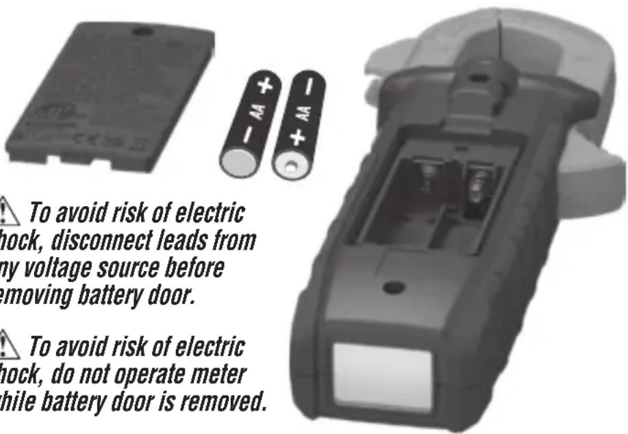
When indicator is displayed on LCD, batteries must be replaced.
- Loosen captive screw and remove battery cover.
- Replace 2 × AA batteries (note proper polarity).
- Replace battery cover and fasten screw securely.
text_image
To avoid risk of electric shock, disconnect leads from my voltage source before removing battery door. To avoid risk of electric shock, do not operate meter while battery door is removed.CLEANING
Be sure meter is turned off and wipe with a clean, dry lint-free cloth. Do not use abrasive cleaners or solvents.
STORAGE
Remove the batteries when meter is not in use for a prolonged period of time. Do not expose to high temperatures or humidity. After a period of storage in extreme conditions exceeding the limits mentioned in the General Specifications section, allow the meter to return to normal operating conditions before using.
FCC & IC COMPLIANCE
See this product's page at www.kleintools.com for FCC compliance information.
Canada ICES-003 (B) / NMB-003 (B)
WARRANTY
Do not place equipment and its accessories in the trash. Items must be properly disposed of in accordance with local regulations. Please see www.epa.gov/recycle for additional information.
CUSTOMER SERVICE
KLEIN TOOLS, INC.
450 Bond Street Lincolnshire, IL 60069 1-800-553-5346
customerservice@kleintools.com www.kleintools.com
ESPAÑOL
CL490
text_image
NCV =8.0.0.0 ACCEUKCA

Intertek
5001748
CAT III
600V
text_image
NCV mV μA =8.0.0.0CEUKCA

Intertek 5001748
CAT III 600V