HVNCVT-1 - Measuring equipment Klein Tools - Free user manual and instructions
Find the device manual for free HVNCVT-1 Klein Tools in PDF.


| Product Type | Dual-Range Non-Contact High Voltage Tester |
| Brand | Klein Tools |
| Model | HVNCVT-1 |
| Low Voltage Range | 50 V to 1.5 kV AC |
| High Voltage Range | 1.5 kV to 132 kV AC |
| Power Supply | One 9V battery |
| Power Consumption | Less than 5 µA (off), less than 40 mA (operating) |
| Operating Temperature | 0°C to 50°C |
| Storage Temperature | -10°C to 50°C |
| Dimensions (tester) | 330 x 80 x 67 mm |
| Dimensions (case) | 356 x 203 x 89 mm |
| Weight | 227 g (8 oz) |
| Main Functions | Non-contact AC voltage detection, cable fault identification, high voltage verification, live cable tracing, grounding equipment verification |
| Indicators | Blue LEDs (voltage present), Red LEDs (range selection) |
| Buttons | Power On/Off, TEST, Low Range, High Range |
| Safety | Use with insulating rod for high voltage; adhere to OSHA minimum approach distances; test on a known live circuit before each use |
| Maintenance and Cleaning | Wipe with a clean, lint-free cloth; do not use abrasive cleaners or solvents |
| Spare Parts and Repairability | User-replaceable 9V battery; no other spare parts available |
| Warranty | See website www.kleintools.com/warranty |
| General Information | Double insulation; compliant with safety standards; for use by qualified personnel only |
Frequently Asked Questions - HVNCVT-1 Klein Tools
User questions about HVNCVT-1 Klein Tools
0 question about this device. Answer the ones you know or ask your own.
Ask a new question about this device
Download the instructions for your Measuring equipment in PDF format for free! Find your manual HVNCVT-1 - Klein Tools and take your electronic device back in hand. On this page are published all the documents necessary for the use of your device. HVNCVT-1 by Klein Tools.
USER MANUAL HVNCVT-1 Klein Tools
Dual-Range High-Voltage Non-Contact Tester
Low Range: 50V to 1.5kV AC
High Range: 1.5kV to 132kV AC
Español pg. 13
Français pg. 25
KLEIN TOOLS®

For Professionals... Since 1857™
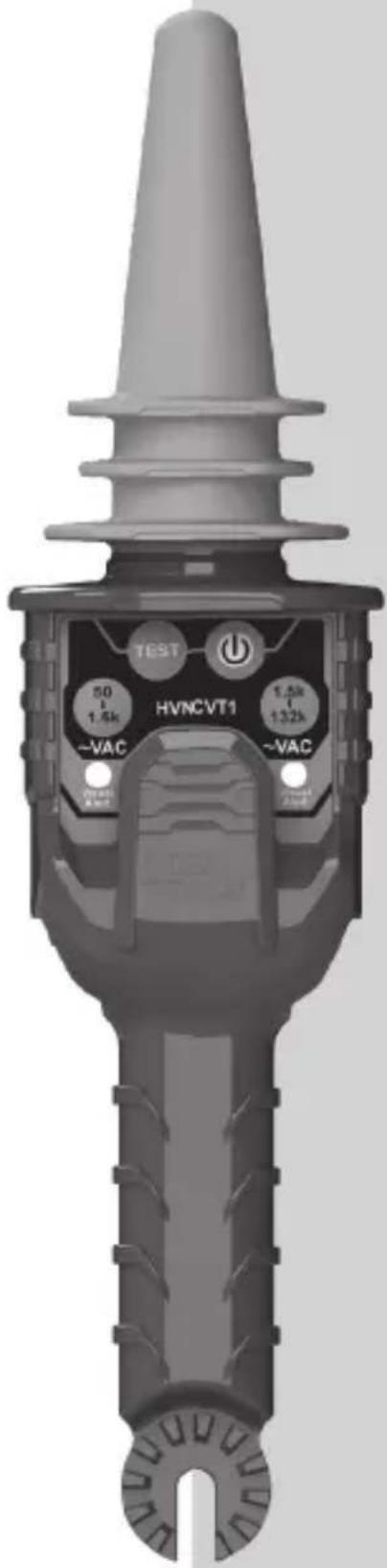
HVNCVT1
text_image
TEST 50 1.5k HVNCVT1 -VAC 1.5k 1.32k -VACGENERAL SPECIFICATIONS
The Dual-Range High-Voltage Non-Contact Tester (HVNCVT1) checks for the presence of AC voltage without making any disconnection in cables, wall sockets, fuses, circuit breakers, junction boxes, etc. No current flow is needed for correct operation. The tester warns against dangerous voltage from low to high voltage applications up to 132kV without contacting the energized conductor. The low-range setting should be used for detecting 50V AC to 1.5kV AC. It may be used as a hand-held device ONLY when checking for low voltage. The high-range setting should be used for detecting 1.5kV AC to 132kV AC. It should ONLY be used with a hot stick when checking for high voltage.
Always follow approved work safety practices and clearances per OSHA Sub-parts R & V and all company work rules. For Minimum Approach Distances (MAD), see OSHA Tables R-6 and R-7 (pages 8 & 9) in this manual.
- Operating Temperature: 32° to 122°F (0° to 50°C) @ 85% relative humidity
• Storage Temperature: 14° to 122°F (-10° to 50°C) @ 85% relative humidity - Dimensions: Tester: 13" x 3.15" x 2.64" (330 x 80 x 67mm)
Case: 14" x 8" x 3.5" (356 x 203 x 89 mm)
• Weight: 8 oz. (227 g)
• Power Source: One 9V battery
• Power Consumption: Off: Less than 5uA
Low range mode: (50V to 1.5kV AC) Less than 40mA
High range mode: (1.5kV to 132kV AC) Less than 40mA
Specifications subject to change.
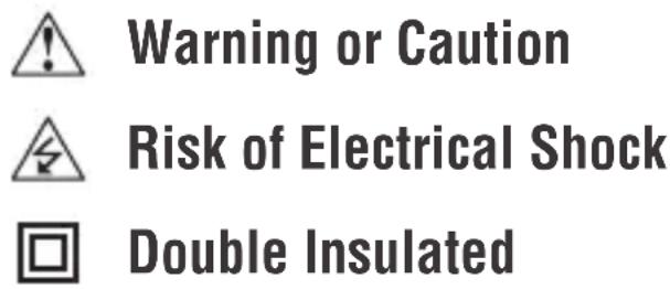
SYMBOLS
text_image
Warning or Caution Risk of Electrical Shock Double Insulated⚠️ WARNINGS
To ensure safe operation and service of the tester, follow these instructions.
Failure to observe these warnings can result in severe injury or death.
- Use extreme caution when testing live electrical circuits due to risk of injury from electrical shock.
- When testing for high voltage, always use hot sticks and rubber gloves meeting industry standards.
- Follow approved work safety practices and clearances per OSHA Sub-parts R & V and your company work rules.
- Always test on a known live circuit to verify tester functionality prior to use.
- Do not exceed the limits marked on the instrument itself. Never test voltage more than 132kV AC RMS.
- Never ground yourself when taking measurements. Do not touch exposed circuit elements.
- Observe the proper safety precautions when working with voltage above 30V AC RMS to avoid electrical shock hazard.
- Do not assume equipment or conductors are, or will remain, de-energized. Always install proper grounding devices before starting procedure.
- Do not operate tester in an explosive atmosphere.
- Do not expose tester to rain or moisture. This increases the risk of fire or electric shock.
- Do not rely on this tester for shielded wire or cable with concentric neutrals.
- Do not let the unit make contact with live line voltage. Do not touch any exposed wiring, connections or other energized parts of an electrical circuit.
- 3-phase feeder cables with conductors close to each other may self-cancel the electric field and not be detected by the device. Verify that the phase conductors are separated by at least 15" (381 mm) before testing for AC voltage.
fEatuRE DEtaILS
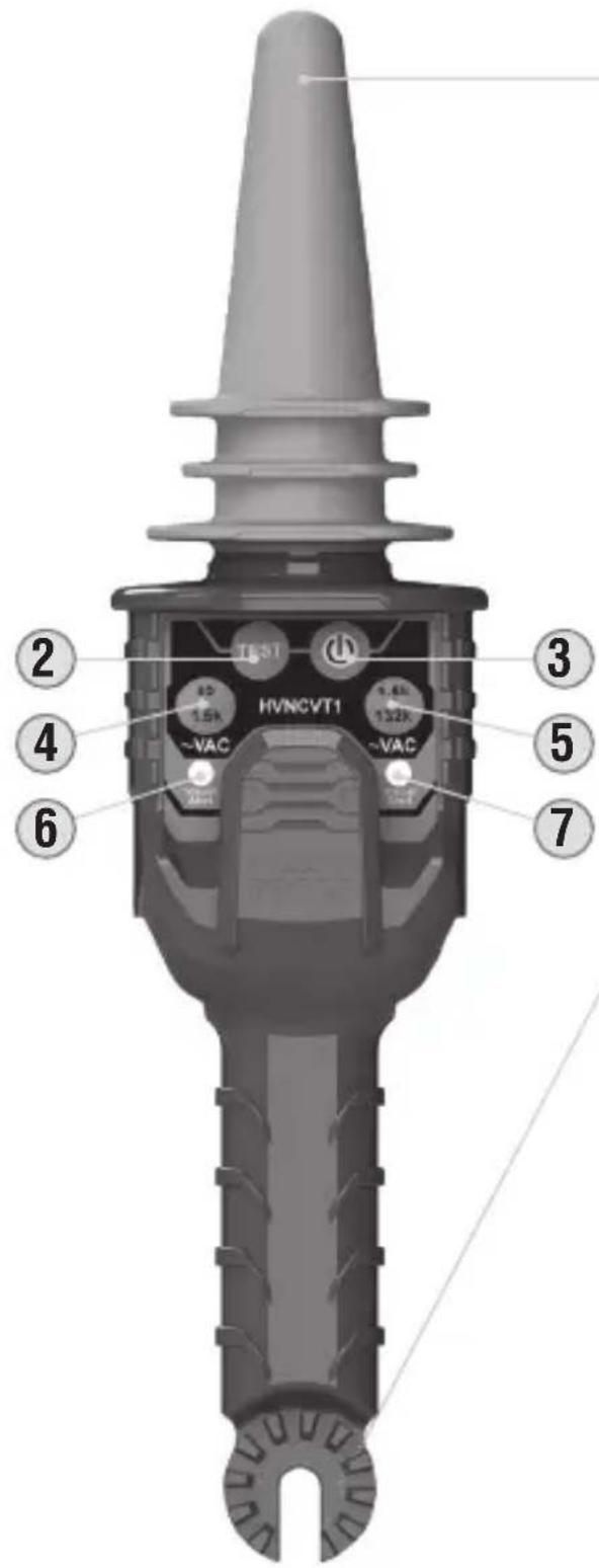
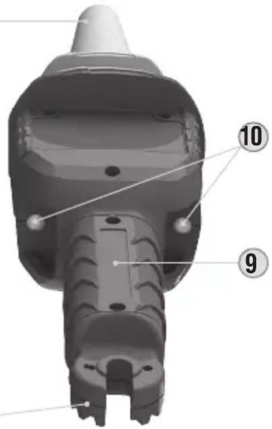
Back of TesterFront of Tester
text_image
HVNCVT1 TEST 15A VAC VAC 3 4 6 7 51
8
text_image
Technical diagram of a mechanical component with numbered parts labeled 9 and 10- Voltage sensor
- "TEST" button
- On/Off button
- Low-Range button
- High-Range button
- Red Low-Range LED
- Red High-Range LED
- Hot stick connection point
- Battery cover
- Blue LED voltage indicators
OPERATING INSTRUCTIONS
FOR USE BY TRAINED PERSONNEL ONLY
Anyone using this instrument should be knowledgeable and trained about the risks involved with measuring medium and high voltage. They must also understand the importance of taking safety precautions as well as testing the instrument before and after using it to ensure that it is in good working condition.
EXAMPLES OF APPLICATIONS:
• Non-contact detection of live AC voltage
• Finding faults in cables
- Checking and detecting live high voltage cables
- Tracing live wires
- Checking grounding equipment
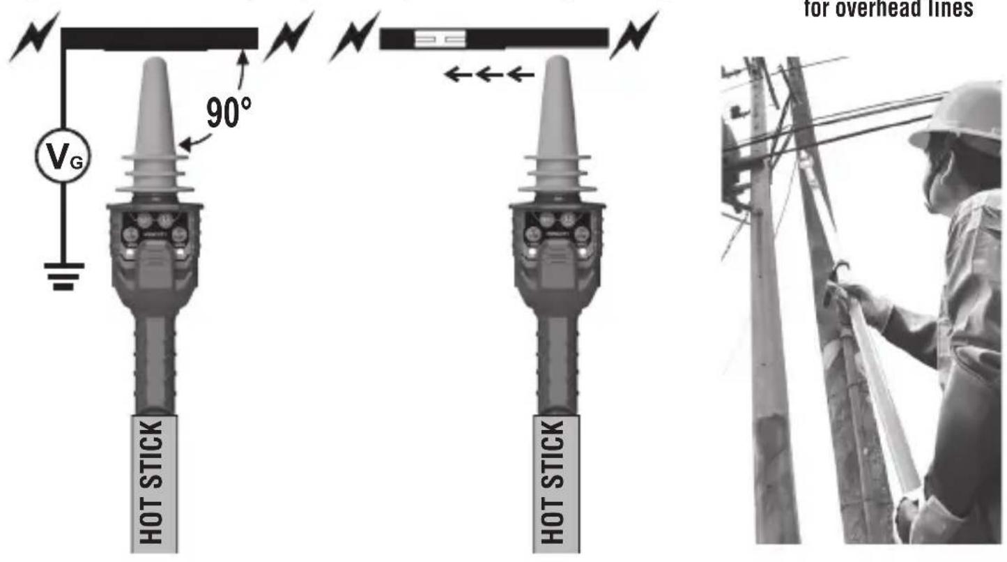
Fig. 1: Ideal detection angle Fig. 2: Finding a cable fault Fig. 3: Voltage detection
text_image
V_G 90° for overhead lines HOT STICK HOT STICKOPERATING INSTRUCTIONS
Prior to use, always inspect the tester for visible signs of damage. If there is any sign of damage, or if the tester does not operate correctly, discontinue use.
Always test on a known live circuit to verify tester functionality. The tester should be used as an indication only.
Tester should be kept clean and dry. If it is not, wipe with a clean, dry lint-free cloth.
MODES OF OPERATION
The HVNCVT1 can operate in two ranges. In low-range mode, the red LED 6 below the low-range button 4 will illuminate. In high-range mode, the red LED 7 below the high-range button 5 will illuminate. See FEATURE DETAILS for locations of red LEDs.
ON/OFF BUTTON
Press the on/off button 3 to turn the unit on or off. When the unit is turned on, the two blue LEDs 10 will flash and the unit will emit a high-pitched beep sound. See FEATURE DETAILS for locations of blue LEDs.
"TEST" BUTTON
Press and hold the TEST button 2 to perform a self-test on the unit. Look for a steady blue LED light 10 and listen for a steady beep sound. This self-test function ONLY confirms battery sufficiency, system integrity, and operation/active mode. Always test on known live circuit to verify tester functionality prior to use. If the two blue LEDs do not glow and the beep sound is not present, replace battery.
LOW-RANGE BUTTON
When the unit is turned on, press the low-range button 4 to switch the unit to the low-range setting. Look for a steady red LED 6 below the low-range button. Also look for the two blue LEDs 10 to blink and listen for a beep sound.
The Low range is 50V AC to 1.5kV AC.
Place the probe tip of the tester 1 near a low voltage source, but not touching it. Look for the blue LEDs 10 to blink quickly and listen for a quickened beep sound when voltage is present. As the probe tip gets closer to the voltage source, the blue LEDs and beep sound will be constant. See Fig. 1 on page 5 for ideal detection angle. Always
OpERatInG InStRuCtlOnS
maintain the minimum approach distances listed in OSHA Tables R-6 and R-7 on pages 8 & 9 in this manual.
HIGH-RanGE ButtOn
Before using the unit in High range, hot stick must be attached. Only use with hot sticks and rubber gloves meeting industry standards. Always follow approved work safety practices and clearances per OSHA Sub-parts R & V and all company work rules.
When the unit is turned on, press the high-range button 5 to switch the unit to the high-range setting. Look for a steady red LED 7 below the high-range button. Also look for the two blue LEDs 10 to blink and listen for a beep sound.
The High range is 1.5kV AC to 132kV AC.
Place the probe tip of the tester 1 near a high voltage source, but not touching it. Look for the blue LEDs 10 to blink quickly and listen for a quickened beep sound when voltage is present. As the probe tip gets closer to the voltage source, the blue LEDs and beep sound will be constant. See Fig. 1 on page 5 for ideal detection angle. Always maintain the minimum approach distances listed in OSHA Tables R-6 and R-7 on pages 8 & 9 in this manual.
fInDInG fauLtS In CaBLE
The tester may be used for finding faults in some flexible cables. Press the appropriate button for low-range 4 or high-range 5 according to the voltage of the energized cable being detected. Move the tester along (but not touching) the cable, listening for the rapid beeping or steady sound and looking for the rapid blinking or steady light from the blue LEDs 10. When the fault is reached, the unit will no longer beep or blink. See Fig. 2 on page 5. Always maintain the minimum approach distances listed in OSHA Tables R-6 and R-7 on pages 8 & 9 in this manual.
OPERATING INSTRUCTIONS
Always follow approved work safety practices and clearances per OSHA Sub-parts R & V and all company work rules. For Minimum Approach Distances (MAD), see OSHA Tables R-6 and R-7 below.
TABLE R-6 – ALTERNATIVE MINIMUM APPROACH DISTANCES FOR VOLTAGES OF 72.5 kV AND LESS ^1
| Nominal voltage (kV) phase-to-phase | Distance | |||
| Phase-to-ground exposure | Phase-to-phase exposure | |||
| ft. m ft. | m | |||
| 0.050 to 0.300^2 | Avoid Contact | Avoid Contact | Avoid Contact | Avoid Contact |
| 0.301 to 0.750^2 | 1.09 0.33 | 1.09 0.33 | ||
| 0.751 to 5.0 2.07 0.63 | 2.07 0.63 | |||
| 5.1 to 15.0 2.14 0.65 | 2.24 0.68 | |||
| 15.1 to 36.0 2.53 0.77 | 2.92 0.89 | |||
| 36.1 to 46.0 2.76 0.84 | 3.22 0.98 | |||
| 46.1 to 72.5 3.29 1.00 | 3.94 1.20 | |||
^1 Employers may use the minimum approach distances in this table provided the worksite is at an elevation of 3,000 feet (900 meters) or less. If employees will be working at elevations greater than 3,000 feet (900 meters) above mean sea level, the employer shall determine minimum approach distances by multiplying the distances in this table by the correction factor in OSHA's Table R-5 Altitude Correction Factor, corresponding to the altitude of the work.
^2 For single-phase systems, use voltage-to-ground.
OPERATING INSTRUCTIONS
TABLE R-7-ALTERNATIVE MINIMUM APPROACH DISTANCES FOR VOLTAGES OF MORE THAN 72.5 kV ^123
| Nominal voltage (kV) phase-to-phase | Distance | |||
| Phase-to-ground exposure ft. m ft. m | Phase-to-phase exposure | |||
| 72.6 to 121.0 3.71 1.13 4.66 1.42 | ||||
| 121.1 to 145.0 4.27 1.30 5.38 1.64 | ||||
| 145.1 to 169.0 4.79 1.46 6.36 1.94 | ||||
| 169.1 to 242.0 6.59 2.01 10.10 3.08 | ||||
| 242.1 to 362.0 11.19 3.41 18.11 5.52 | ||||
| 362.1 to 420.0 13.94 4.25 22.34 6.81 | ||||
| 420.1 to 550.0 16.63 5.07 27.03 8.24 | ||||
| 550.1 to 800.0 22.57 6.88 37.34 11.38 | ||||
^1 Employers may use the minimum approach distances in this table provided the worksite is at an elevation of 3,000 feet (900 meters) or less. If employees will be working at elevations greater than 3,000 feet (900 meters) above mean sea level, the employer shall determine minimum approach distances by multiplying the distances in this table by the correction factor in OSHA's Table R-5 Altitude Correction Factor, corresponding to the altitude of the work.
^2 Employers may use the phase-to-phase minimum approach distances in this table provided that no insulated tool spans the gap and no large conductive object is in the gap.
^3 The clear live-line tool distance shall equal or exceed the values for the indicated voltage ranges.
OPERATING INSTRUCTIONS
PROTECTIVE CLOTHING AND PERSONAL PROTECTIVE EQUIPMENT (PPE)
| TABLE 130.7 (C) (16) FROM NFPA 70E 2015Note below that this new PPE category table no longer references a category 0. | ||||
| PPE Category* | Clothing | Min. APTV Rating Cal/ cm^2 | Required Garments | Required Protective Equipment |
| 1 | Arc-rated clothing ^1 and PPE | 4 | Long-sleeve shirt and pants or coverall. Flash suit hood or face shield ^2 . Jacket, parka, rainwear or hard hat liner (AN). | Hard hat. Safety glasses or safety goggles (SR). Hearing protection (ear canal inserts). Heavy duty leather gloves ^3 . Leather footwear (AN). |
| 2 | Arc-rated clothing ^1 and PPE | 8 | Long-sleeve shirt and pants or coverall. Flash suit hood or face shield ^2 and balaclava. Jacket, parka, rainwear or hard hat liner (AN). | Hard hat. Safety glasses or safety goggles (SR). Hearing protection (ear canal inserts). Heavy duty leather gloves ^3 . Leather footwear (AN). |
| 3 | Arc-rated clothing system ^1 and PPE | 25 | Long sleeve shirt (AR). Pants (AR). Coverall (AR). Flash suit jacket (AR). Flash suit pants (AR). Flash suit hood. Gloves ^1 . Jacket, parka, rainwear or hard hat liner (AN). | Hard hat. Safety glasses or safety goggles (SR). Hearing protection (ear canal inserts). Leather footwear (AN). |
| 4 | Arc-rated clothing system ^3 and PPE | 40 | Long sleeve shirt (AR). Pants (AR). Coverall (AR). Flash suit jacket (AR). Flash suit pants (AR). Flash suit hood. Gloves ^1 . Jacket, parka, rainwear or hard hat liner (AN). | Hard hat. Safety glasses or safety goggles (SR). Hearing protection (ear canal inserts). Leather footwear (AN). |
AN = as needed (optional) AR = as required SR = selection required
*One of the 3 basic methods is used to determine an HRC for a job task.
^1 Arc rating is defined in article 100 NFPA 70E 2015 Edition.
^2 Face shields are to have wrap-around guarding to protect not only the face but also the forehead, ears and neck, or alternatively, an arc-rated flash suit hood is required to be worn.
^3 If rubber insulating gloves with leather protectors are used, additional leather or arc-rated gloves are not required. The combination of rubber insulating gloves with leather protectors satisfies the arc flash protection requirement.
MAINTENANCE
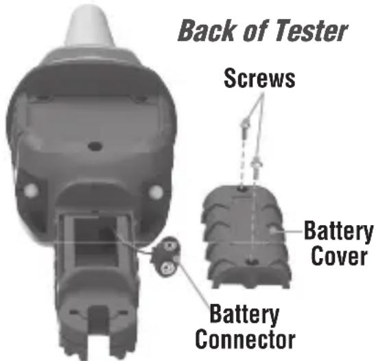
BATTERY REPLACEMENT
- Unscrew the battery cover on the rear and lift the battery cover off the tester.
- Remove old battery.
- Replace with a new battery (9V).
- Reinstall the battery cover and fasten the cover screws.
text_image
Back of Tester Screws Battery Cover Battery ConnectorCLEANING
Be sure tester is turned off and wipe with a clean, dry lint-free cloth. Do not use abrasive cleaners or solvents.
STORAGE
If the tester is not to be used for periods of longer than 60 days, remove the battery and store separately from the tester.
WARRANTY
Do not place equipment and its accessories in the trash. Items must be properly disposed of in accordance with local regulations.
Please see www.epa.gov or www.erecycle.org for additional information.
CUSTOMER SERVICE
KLEIN TOOLS, INC. 450 Bond Street Lincolnshire, IL 60069 USA
For Professionals... Since 1857™
KLEIN TOOLS, INC. 450 Bond Street Lincolnshire, IL 60069 USA hisupport@kleintools.com www.kleintools.com
natural_image
Worker in hard hat and safety gear inspecting utility pole equipment (no visible text or symbols)For Professionals... Since 1857™
KLEIN TOOLS, INC. 450 Bond Street Lincolnshire, IL 60069 USA
text_image
Technical diagram of a mechanical component with numbered parts labeled 1, 8, 9, and 10natural_image
Worker in hard hat and safety vest inspecting utility pole equipment (no visible text or symbols)INSTRUCTIONS D'UTILISATION
REPLACEMENT DES PILES
For Professionals... Since 1857 ^™
KLEIN TOOLS, INC. 450 Bond Street Lincolnshire, IL 60069 USA