CL220 - Measuring equipment Klein Tools - Free user manual and instructions
Find the device manual for free CL220 Klein Tools in PDF.
User questions about CL220 Klein Tools
0 question about this device. Answer the ones you know or ask your own.
Ask a new question about this device
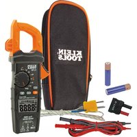
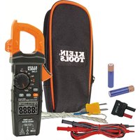
Download the instructions for your Measuring equipment in PDF format for free! Find your manual CL220 - Klein Tools and take your electronic device back in hand. On this page are published all the documents necessary for the use of your device. CL220 by Klein Tools.
USER MANUAL CL220 Klein Tools
- Operating Altitude: 6562 ft. (2000m)
- Relative Humidity: <95% non-condensing
- Accuracy: Values stated at 65° to 83°F (18° to 28°C)
- Temp Coefcient: 0.1 x (Quoted Accuracy) per °C above 28°C or below 18°C, corrections are required when ambient working temp is outside of Accuracy Temp range
- Dimensions: 8.46" x 3.54" x 1.50" (215 x 90 x 38 mm)
- Weight: 11.04 oz. (313 g) including batteries
- Calibration: Accurate for one year
- Auto Power-Off (APO): After approx. 10 minutes of inactivity
- Accuracy: ± (% of reading + # of least significant digits)
- Drop Protection: 6.6 ft. (2m)
- Safety Rating: CATIII 600V, Class 2, Double insulation
OTHER MEASUREMENT APPLICATIONS
- Sampling Frequency: 3 samples per second
- Overload: "OL" indicated on display
- Never use the meter on a circuit with voltages that exceed the category based rating of this meter.
- Do not use the meter during electrical storms or in wet weather.
- Do not use the meter or test leads if they appear to be damaged.
- Use only with CAT III or CAT IV rated test leads.
- Ensure test leads are fully seated into jacks, and keep fingers away from the metal probe contacts when making measurements.
- Use caution when working with voltages above 25V AC RMS or 60V DC. Such voltages pose a shock hazard.
- To avoid false readings that can lead to electrical shock, replace batteries when a low battery indicator appears.
- Do not attempt to measure resistance or continuity on a live circuit.
- Always adhere to local and national safety codes. Use personal protective equipment to prevent shock and arc blast injury where hazardous live conductors are exposed.
- To avoid risk of electric shock, disconnect leads from any voltage source before removing battery door.
- To avoid risk of electric shock, do not operate meter while battery door is removed
WARNINGS - NCV FUNCTION
- When NCV Function is initiated, a blinking or steady red glow and an audible beep indicate voltage present. If no indication, voltage could still be present.
- Before and after each use of the NCVT, verify operation by testing a known working circuit that is within the rating of this unit.
- Never assume neutral or ground wires are de-energized. Neutrals in multi-wire branch circuits may be energized when disconnected and must be retested before handling.
- The NCV tester WILL NOT detect voltage if:
- The wire is shielded.
- The operator is not grounded or is otherwise isolated from an effective earth ground.
- The NCV tester MAY NOT detect voltage if:
- The user is not holding the tester.
- The user is insulated from the tester with a glove or other materials.
- The wire is partially buried or in a grounded metal conduit.
- The tester is at a distance from the voltage source.
- The field created by the voltage source is blocked, dampened, or otherwise interfered with.
- The frequency of the voltage is not a perfect sine wave between 50 and 500Hz.
- The tester is outside of operation conditions (listed in Specifications section).
- Operation may be affected by differences in socket design and insulation thickness and type; tester may not be compatible with some types of standard or tamper resistant (TR) electrical outlets.
- Do not apply to uninsulated hazardous live conductors.
- Detection above 50V is specified under “normal” conditions as specified below. The tester may detect at a different threshold at different conditions, or may not detect at all unless:
- The tip of the tester is within 0.25" of an AC voltage source radiating unimpeded.
- The user is holding the body of the tester with his or her bare hand.
- The user is standing on or connected to earth ground.
- The air humidity is nominal (50% relative humidity).
AC (Alternating Current) DC (Direct Current) Resistance (in Ohms) Audible Continuity Double Insulated Class II Ground Warning or Caution Risk of Electrical Shock Suitable for uninsulated hazardous live conductors V Voltage (Volts) A Amperage (Amps) COM Common NCV Non-Contact Voltage Tester Backlight SEL Select
AC AC (Alternating Current) DC DC (Direct Current) Negative Reading
Data Hold Auto Ranging MAX Maximum Value Hold Low Battery Audible Continuity
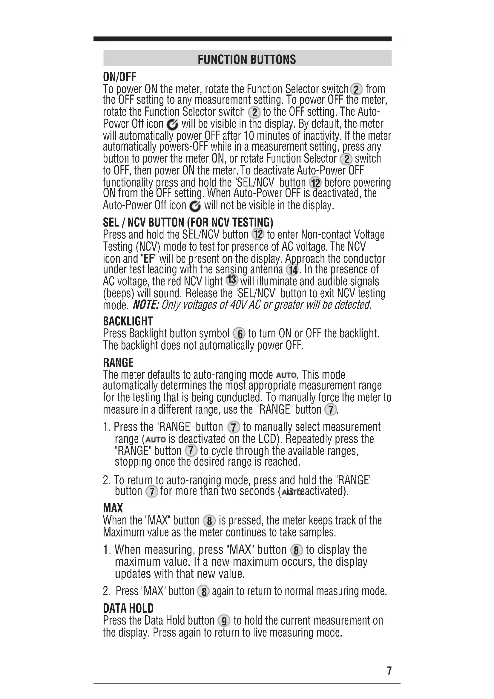
from the OFF setting to any measurement setting. To power OFF the meter, rotate the Function Selector switch
to the OFF setting. The Auto- Power Off icon will be visible in the display. By default, the meter will automatically power OFF after 10 minutes of inactivity. If the meter automatically powers-OFF while in a measurement setting, press any button to power the meter ON, or rotate Function Selector
switch to OFF, then power ON the meter. To deactivate Auto-Power OFF functionality press and hold the "SEL/NCV" button
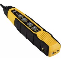
before powering ON from the OFF setting. When Auto-Power OFF is deactivated, the Auto-Power Off icon will not be visible in the display. SEL / NCV BUTTON (FOR NCV TESTING) Press and hold the SEL/NCV button
to enter Non-contact Voltage Testing (NCV) mode to test for presence of AC voltage. The NCV icon and "EF" will be present on the display. Approach the conductor under test leading with the sensing antenna
. In the presence of AC voltage, the red NCV light
will illuminate and audible signals (beeps) will sound. Release the "SEL/NCV" button to exit NCV testing mode. NOTE: Only voltages of 40V AC or greater will be detected. BACKLIGHT Press Backlight button symbol
to turn ON or OFF the backlight. The backlight does not automatically power OFF. RANGE The meter defaults to auto-ranging mode . This mode automatically determines the most appropriate measurement range for the testing that is being conducted. To manually force the meter to measure in a different range, use the "RANGE" button
to manually select measurement range ( is deactivated on the LCD). Repeatedly press the "RANGE" button
to cycle through the available ranges, stopping once the desired range is reached.
for more than two seconds ( is reactivated). MAX When the "MAX" button
is pressed, the meter keeps track of the Maximum value as the meter continues to take samples.
again to return to normal measuring mode. DATA HOLD Press the Data Hold button
Do not test if leads are improperly seated. Results could cause intermittent display readings. To ensure proper connection, firmly press leads into the input jack completely.
TESTING IN CAT III MEASUREMENT LOCATIONS
Ensure the test lead shield is pressed firmly in place. Failure to use the CATIII / CATIV shield increases arc-flash risk.
TESTING IN CAT II MEASUREMENT LOCATIONS
CAT III / CAT IV shields may be removed for CAT II locations. This will allow testing on recessed conductors such as standard wall outlets. Take care not to lose the shields. INCORRECT CORRECT 0.7" (18 mm) 5/32" (4 mm) CL220-1390364ART.indd 8CL220-1390364ART.indd 8 10/18/2021 12:29:16 PM10/18/2021 12:29:16 PM9 Dwg Name: CL220-1390364ART Dwg No: 1390364 ECO No: 42201 Rev: C Pkg Dwg Ref: 1290186 Finish Coat Requirements: N/A OPERATING INSTRUCTIONS AC CURRENT (LESS THAN 400A) AC Current is measured by pressing the clamp trigger
to open the clamp and placing it around a current-carrying wire. When measuring, care should be taken to ensure that the clamp is completely closed with trigger
fully released, and that the wire passes perpendicularly through the center of the clamp in line with the arrow markings
to the 200/400 A setting.
2. Place clamp around wire. The current measurement will be shown
in the display. NOTE: If the measurement is less than 20A, rotate the Function Selector switch
to the 2/20 A setting for improved resolution. Disconnect test leads when measuring with the clamp.
LIVE CABLE NEUTRAL WIRE CL220-1390364ART.indd 9CL220-1390364ART.indd 9 10/18/2021 12:29:19 PM10/18/2021 12:29:19 PM10 Dwg Name: CL220-1390364ART Dwg No: 1390364 ECO No: 42201 Rev: C Pkg Dwg Ref: 1290186 Finish Coat Requirements: N/A OPERATING INSTRUCTIONS AC/DC VOLTAGE (LESS THAN 600V)
1. Insert RED test lead into VΩ jack
, and BLACK test lead into COM jack
to the DC Voltage or AC Voltage setting. Note "
2. Apply test leads to the circuit to be tested to measure voltage.
The meter will auto-range to display the measurement in the most appropriate range. NOTE: If "–" appears on the LCD, the test leads are being applied to the circuit in reverse. Swap the position of the leads to correct this. NOTE: When in a voltage setting and the test leads are open, readings of order mV may appear on the display. This is noise and is normal. By touching the test leads together to close the circuit the meter will measure zero volts. NOTE: To access mV range for V AC the "RANGE" button
must be used. NOTE: When voltages in excess of 25V AC or 60V DC are measured, the Hazardous Voltage Indicator will appear on the display. ENGLISH
1. Insert RED test lead into V jack
, and BLACK test lead into COM jack
to the Resistance setting. The resistance symbol will appear on the display.
2. Remove power from circuit.
3. Measure resistance by connecting test leads to circuit. The
meter will auto-range to display the measurement in the most appropriate range. NOTE: When in a Resistance setting and the test leads are open (not connected across a resistor), or when a failed resistor is under test, the display will indicate O.L. This is normal. DO NOT attempt to measure resistance on a live circuit. CONTINUITY
1. Insert RED test lead into V jack
and BLACK test lead into COM jack
to the Continuity setting.
2. Remove power from circuit.
3. Test for continuity by connecting conductor or circuit with test
leads. If resistance is measured less than 10Ω, an audible signal will sound and display will show a resistance value indicating continuity. If circuit is open, display will show "OL". DO NOT attempt to measure continuity on a live circuit. Red leadBlack lead Red leadBlack lead CL220-1390364ART.indd 11CL220-1390364ART.indd 11 10/18/2021 12:29:24 PM10/18/2021 12:29:24 PM12 Dwg Name: CL220-1390364ART Dwg No: 1390364 ECO No: 42201 Rev: C Pkg Dwg Ref: 1290186 Finish Coat Requirements: N/A OPERATING INSTRUCTIONS TEMPERATURE
1. Insert K-type thermocouple into the VΩ
jacks (observe polarity markings on thermocouple and meter), and rotate function selector switch
once. Ensure that the appropriate icon (either
) appears on the display.
2. To measure temperature, make contact between the
thermocouple tip and the object being measured. When thermocouple tip and object are in thermal equilibrium, the measurement on the display will stabilize. Remove thermocouple before switching meter to other measurement functions. The thermocouple included with the original purchase is suitable for temperatures below 446°F / 230°C only. To measure higher temperatures, a K-type thermocouple with the appropriate measurement range should be used. ENGLISH K-Type Thermocouple CL220-1390364ART.indd 12CL220-1390364ART.indd 12 10/18/2021 12:29:25 PM10/18/2021 12:29:25 PM13 Dwg Name: CL220-1390364ART Dwg No: 1390364 ECO No: 42201 Rev: C Pkg Dwg Ref: 1290186 Finish Coat Requirements: N/A MAINTENANCE BATTERY REPLACEMENT When indicator is displayed on LCD, batteries must be replaced.
1. Loosen captive screw and remove battery cover.
2. Replace 3 x AAA batteries (note proper polarity).
3. Replace battery cover and fasten screw securely.
o avoid risk of electric shock, disconnect leads from any voltage source before removing battery door. To avoid risk of electric shock, do not operate meter while battery door is removed.
CL220-1390364ART.indd 13CL220-1390364ART.indd 13 10/18/2021 12:29:26 PM10/18/2021 12:29:26 PM14 Dwg Name: CL220-1390364ART Dwg No: 1390364 ECO No: 42201 Rev: C Pkg Dwg Ref: 1290186 Finish Coat Requirements: N/A ENGLISH CLEANING Be sure meter is turned off and wipe with a clean, dry lint-free cloth. Do not use abrasive cleaners or solvents. STORAGE Remove the batteries when meter is not in use for a prolonged period of time. Do not expose to high temperatures or humidity. After a period of storage in extreme conditions exceeding the limits mentioned in the General Specifications section, allow the meter to return to normal operating conditions before using. WARRANTY www.kleintools.com/warranty DISPOSAL / RECYCLE Do not place equipment and its accessories in the trash. Items must be properly disposed of in accordance with local regulations. Please see www.epa.gov/recycle for additional information. CUSTOMER SERVICE KLEIN TOOLS, INC. 450 Bond Street Lincolnshire, IL 60069 1-800-553-4676 customerservice@kleintools.com www.kleintools.com CL220-1390364ART.indd 14CL220-1390364ART.indd 14 10/18/2021 12:29:27 PM10/18/2021 12:29:27 PM15 Dwg Name: CL220-1390364ART Dwg No: 1390364 ECO No: 42201 Rev: C Pkg Dwg Ref: 1290186 Finish Coat Requirements: N/A
- Dimensions: 215x 90x 38mm (8,46x 3,54x 1,50po)