
C18DMR - Saw HiKOKI - Free user manual and instructions
Find the device manual for free C18DMR HiKOKI in PDF.
| Brand | HiKOKI |
| Model | C18DMR |
| Type | Cordless circular saw |
| No-load speed | 3400 min⁻¹ |
| Cutting capacity at 90° | 57 mm |
| Cutting capacity at 45° | 40 mm |
| Blade diameter | 165 mm |
| Blade bore | 16 mm / 20 mm / 30 mm (depending on washer) |
| Power supply | Rechargeable 18 V battery (Ni-Cd, Ni-MH or Li-ion) |
| Weight | 3.6 kg |
| Electric brake | Yes |
| Integrated light | 12 V, 5 W lamp |
| Bevel adjustment | Up to 50° |
| Depth adjustment | Yes |
| Parallel guide | Included |
| Lower guard | Auto-retracting |
| Sound power level | 106 dB(A) |
| Sound pressure level | 95 dB(A) |
| Vibration level (a_h) | 1.4 m/s² |
| Compatible batteries | EB1820L, EB1826HL, EB1830HL, EB1830X, EB1833X, EBM1830 |
| Included charger | UC24YFA, UC18YG or UC18YRL |
| Included accessories | Saw blade, wrench, guide, charger, battery, plastic case |
| Maintenance | Clean air vents, check carbon brushes, keep guard clean |
| Country of manufacture | France (HiKOKI Power Tools France) |
Frequently Asked Questions - C18DMR HiKOKI
User questions about C18DMR HiKOKI
0 question about this device. Answer the ones you know or ask your own.
Ask a new question about this device
Download the instructions for your Saw in PDF format for free! Find your manual C18DMR - HiKOKI and take your electronic device back in hand. On this page are published all the documents necessary for the use of your device. C18DMR by HiKOKI.
USER MANUAL C18DMR HiKOKI
natural_image
Line drawing of a mechanical device with cutouts and mounting brackets (no text or symbols)C18DL
Read through carefully and understand these instructions before use. Diese Anleitung vor Benutzung des Werkzeugs sorgfältig durchlesen und verstehen. Lire soigneusement et bien assimiler ces instructions avant usage. Prima dell'uso leggere attentamente e comprendere queste instruzioni. Deze gebruiksaanwijzing s.v.p. voor gebruik zorgvuldig doorlezen. Leer cuidadosamente y comprender estas instrucciones antes del uso. Antes de usar, leia com cuidado para assimilar estas instruções. Διαβάστε προσεκτικά και κατανοήςετε αυτές τις οδηγίες πριν τη χρήση.
Handling instructions Bedienungsanleitung Mode d'emploi Istruzioni per l'uso Gebruiksaanwijzing Instrucciones de manejo Instruções de uso Οδηγίες χειρισμού
natural_image
Line drawing of a mechanical device mounted on a flat base, labeled with number 1 (no text or symbols on the device itself)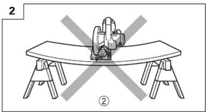
natural_image
Line drawing of a table with a sewing machine and two chairs, no text or symbols present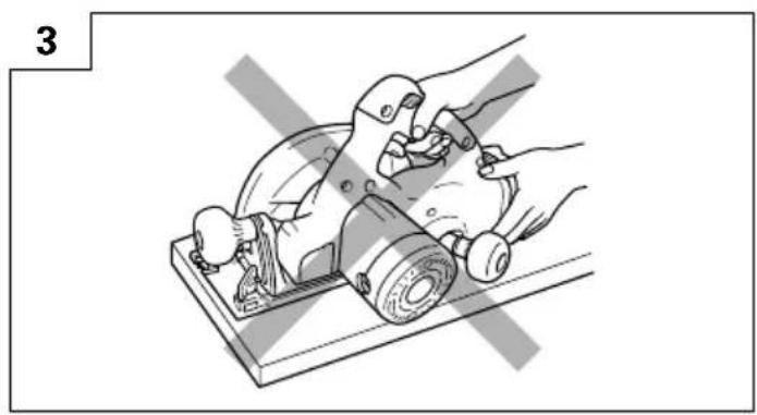
natural_image
Illustration of hands using a power tool on a cutting board (no text or symbols)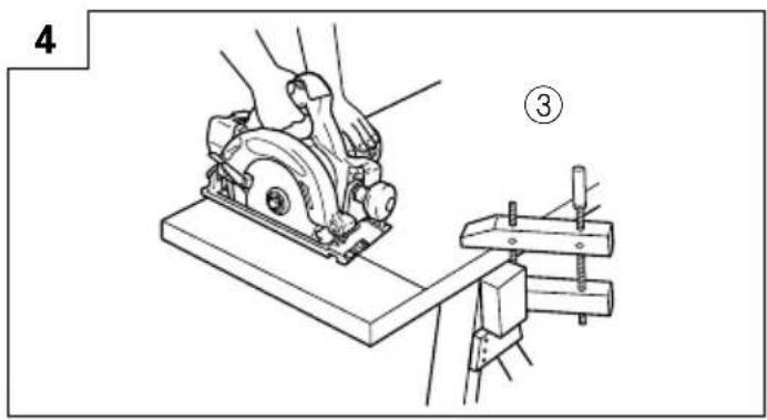
natural_image
Illustration of a hand operating a manual tool on a workbench (no text or symbols visible)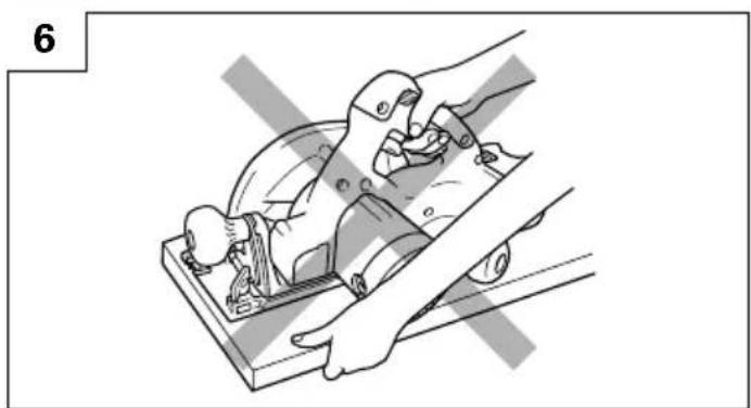
natural_image
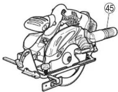
Illustration of a hand using a tool to cut a mechanical component, no text or symbols present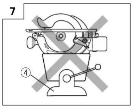
13 14
15
16
17 18
19(A)
19(B)
20 21
22 23
24
25
26 27
natural_image
Technical line drawing of a mechanical assembly with no visible text or symbols| English Deutsch Français | |||
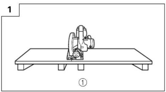
| 1 | To avoid kickback, do support board or panel near the cut. | Unterstützen Sie das Brett bzw. die Tafel in der Röhe des Schnittes, um Rückschlag zu verhüten. | Pour éviter tout retour de lame, soutenir la planche ou le panneau près de la ligne de coupe. |
| 2 | Don't support board or panel away from the cut. | Unterstützen Sie das Brett bzw. die Tafel nicht entfernt von der Schnittstelle. | Ne pas soutenir la planche ou le panneau loin de la ligne de coupe. |
| 3 | A TYPICAL ILLUSTRATION OF TYPISCHE PROPER HAND SUPPORT HANDUNTERSTUTZUNG | EXEMPLE TYPE DE SOUTIEN MANUEL DE LA SCIE, DE SOUTIEN LA PIECE ET D'ACHEMINEMENT DU CORDON | |
| 4 | Vise Schraubstock Etau | ||
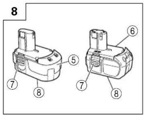
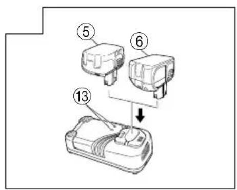
| 5 | 18V Ni-cd or Ni-MH 18V Ni-cd oder Rechargeable battery Wiederaufladbare Batterie Ni-Cd ou Ni-MH, 18V | ||
| 6 | 18V Li-ion Rechargeable battery | 18V Li-ion Wiederaufladbare Batterie | Batterie rechargeable Li-ion, 18V |
| 7 | Latch Schnapper Loquet | ||
| 8 | Nameplate Bezeichnungsschild | Plaque signalétique | |
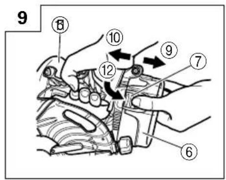
| 9 | Pull out | Herausziehen Tirer | |
| 10 | Insert | Einsatz | Insérer |
| 11 | Handle | Griff | Poignée |
| 12 | Push | Drücken | Pousser |
| 13 | Pilot lamp | Kontrollampe | Lampe pilote |
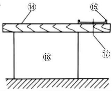
| 14 | Lumber | Schnittholz | Bois |
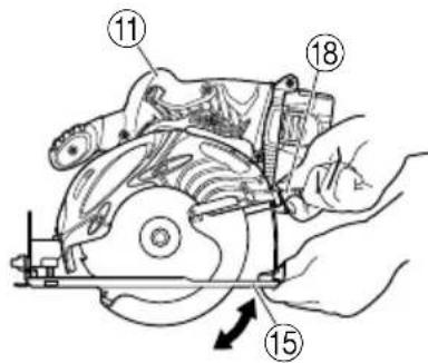
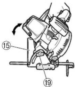
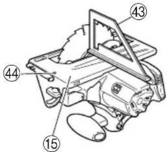
| 15 | Base | Grundplatte | Base |
| 16 | Workbench | Werkbank | Etabli |
| 17 | Saw blade | Sägeblatt | Lame de la scie |
| 18 | Wing nut | Flügelschraube | Ecrou à ailettes |
| 19 | Wing bolt | Flügelschraube | Boulon-papillon |
| 20 | Premarked line | Versetzt-Markierung Ligne de repère | |
| 21 | Front scale when not inclined | Frontskala wenn nicht geneigt | Echelle avant quand non incliné |
| 22 | Front scale at 45° incline | Frontskala bei 45° -Neigung | Echelle avant quand incliné à 45° |
| 23 | Knob bolt | Rändelschraube | Tête de boulon |
| 24 | Guide | Führung | Guide |
| 25 | Switch lock | Schalterverriegelung | Verrou d'interrupteur |
| 26 | Switch trigger | Abzugschalter | Gâchette |
| 27 | Left-hand bolt | Linke Schraube | Boulon gauche |
| 28 | Lock lever | Sperrhebel | Levier de blocage |
| 29 | Box wrench Steckschlüssel | Clef à béquille | |
| 30 | Lower guard lever | Unterer Schutzabdeckungshebel | Levier du protecteur inférieur |
| 31 | Saw cover | Sägeabdeckung | Couvercle de la scie |
| 32 | Washer (B) | Unterlegscheibe (B) | Rondelle (B) |
| 33 | Washer (A) | Unterlegscheibe (A) | Rondelle (A) |
| 34 | Spindle | Achse Arbre | |
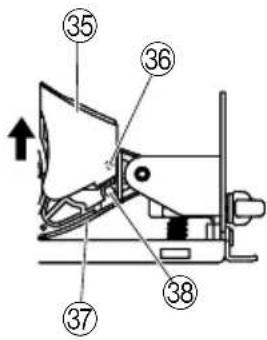
| 35 | Light cover | Lampenabdeckung | Couvercle d'éclairage |
| 36 | Convex | Konvex | Convexe |
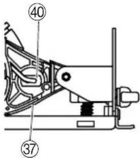
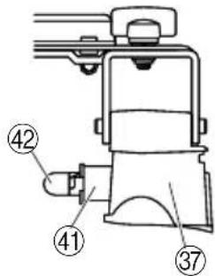
| 37 | Housing | Gehäuse | Boîtier |
| 38 | Concave | Konkav Concave | |
| 39 | Arrow-marked | Pfeilmarkierung | Marqué d'une flèche |
| 40 | Back of the socket | Rückseite des Sockels Dos de la douille | |
| 41 | Socket | Sockel | Douille |
| 42 | Light bulb | Birne | Ampoule |
| 43 | Square Winkel | Equerre | |
| 44 | Slotted set screw | Schaftschraube | Vis sans fin |
| 45 | Dust collector | Staubsauger | Collecteur à poussière |
| Italiano Nederlands Español | |||
| 1 | Per evitare rinculo, appoggiare l'asse o il pannello vicino al taglio. | Om terugslag te voorkomen, dient u plank of paneel in de buurt van de zaagsnede te ondersteunen. | Para evitar el contragolpe, apoye la tabla o el panel cerca del lugar de corte. |
| 2 | Non appoggiare la tavola o il pannello löntano dal taglio. | Ondersteuning op te grote afstand van de zaagsnede is onvoldoende. | No apoye la tabla o el panel lejos del lugar de corte. |
| 3 | ILLUSTRAZIONE TIPO DI UN SUPPORTO MANO CORRETTO | TYPISCH VOORBEELD HOE DE MACHINE VASTGEHOUDEN DIENT TE WORDEN. | UNA ILLUSTRACION TÍPICA DE LA SUJECCIÓN DE LA SIERRA, APOYO DE LA PIEZA DE TRABAJO Y COLOCACIÓN DEL CABLE DE ALIMENTACIÓN |
| 4 | Morsa Bankschroef Tornillo de banco | ||
| 5 | Batteria ricaricabile Ni-cd o 18V Ni-cd of Ni-MH Oplaadbare Batería recargable de Ni-cd o Ni-MH 18V batterij Ni-MH de 18V | ||
| 6 | Batteria ricaricabile Li-ion 18V 18V | Li-ion Oplaadbare batterij | Batería recargable de Li-ion de 18V |
| 7 | Fermo Vergrendeling Enganche | ||
| 8 | Piastrina Naamplaatje Placa de características | ||
| 9 | Estrarre Uittrekken Sacar | ||
| 10 | Inserire Insteken Insertar | ||
| 11 | Impugnatura | Handgreep | Mango |
| 12 | Spingere | Drukken Presionar | |
| 13 | Spia | Kontrolelampje | Lámpara piloto |
| 14 | Legno | Zaaghout | Madera útil |
| 15 | Base | Basisplaat Base | |
| 16 | Banco di lavoro | Werkbank | Banco de trabajo |
| 17 | Lame della sega | Zaagblad | Cuchilla de sierra |
| 18 | Manopola | Knop Perilla | |
| 19 | Bullone a farfalla | Vleugelmoer | Perno de mariposa |
| 20 | Traccia del taglio | Markeerlijn | Línea de trazado |
| 21 | Scala frontale non inclinata | Voorste schaal bij niet hellend zaagblad | Escala frontal sin inclinación |
| 22 | Scala frontale inclinata a 45° | Voorste schaal bij hellend zaagblad (45°) | Escala frontal con 45° de inclinación |
| 23 | Manopola bullone | Knopbout Perno de bola | |
| 24 | Guida | Aanslagplaat | Guía |
| 25 | Blocco interruttore | Vergrendeling Bloqueo del interruptor | |
| 26 | Interruttore a grilletto | Trekkerschakelaar | Interruptor de gatillo |
| 27 | Bullone sinistro | Linker bout | Perno de apriete a la izquierda |
| 28 | Leva di bloccaggio | Palhefboom | Palanca de cierre |
| 29 | Chiave fissa a collare | Steeksleutel | Llave anular |
| 30 | Leva griglia inferiore | Hendel van onderste afscherming | Palanca de protección inferior |
| 31 | Carter della sega | Zaagdek | Cubierta de la sierra |
| 32 | Rondella (B) | Onderlegschijf (B) | Arandela (B) |
| 33 | Rondella (A) | Onderlegschijf (A) | Arandela (A) |
| 34 | Asse | As | Husilio |
| 35 | Coprilampada | Lichtkap Cubierta de la luz | |
| 36 | Convesso | Bol | Parte convexa |
| 37 | Carcassa | Behuizing Alojamiento | |
| 38 | Concavo Hol | Parte cóncava | |
| 39 | Freccia | Pijlmarkering | Marca de flecha |
| 40 | Retro dello zoccolo | Achterkant fitting | Parte trasera del portalámparas |
| 41 | Zoccolo Fitting | Portalámparas | |
| 42 | Lampadina | Lampje | Bombilla de luz |
| 43 | Squadra | Windelhaak | Escuadra |
| 44 | Vite senza fine | Koploze schroef | Vástago |
| 45 | Raccoglipolvere | Stof-verzamelaar | Colector de polvo |
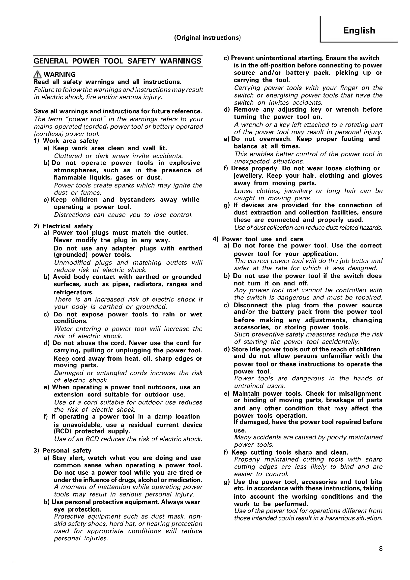
Read all safety warnings and all instructions.
Failure to follow the warnings and instructions may result in electric shock, fire and/or serious injury.
Save all warnings and instructions for future reference.
The term "power tool" in the warnings refers to your mains-operated (corded) power tool or battery-operated (cordless) power tool.
1) Work area safety
a) Keep work area clean and well lit.
Cluttered or dark areas invite accidents.
b) Do not operate power tools in explosive atmospheres, such as in the presence of flammable liquids, gases or dust.
Power tools create sparks which may ignite the dust or fumes.
c) Keep children and bystanders away while operating a power tool.
Distractions can cause you to lose control.
2) Electrical safety
a) Power tool plugs must match the outlet.
Never modify the plug in any way.
Do not use any adapter plugs with earthed (grounded) power tools.
Unmodified plugs and matching outlets will reduce risk of electric shock.
b) Avoid body contact with earthed or grounded surfaces, such as pipes, radiators, ranges and refrigerators.
There is an increased risk of electric shock if your body is earthed or grounded.
c) Do not expose power tools to rain or wet conditions.
Water entering a power tool will increase the risk of electric shock.
d) Do not abuse the cord. Never use the cord for carrying, pulling or unplugging the power tool. Keep cord away from heat, oil, sharp edges or moving parts.
Damaged or entangled cords increase the risk of electric shock.
e) When operating a power tool outdoors, use an extension cord suitable for outdoor use.
Use of a cord suitable for outdoor use reduces the risk of electric shock.
f) If operating a power tool in a damp location is unavoidable, use a residual current device (RCD) protected supply.
Use of an RCD reduces the risk of electric shock.
3) Personal safety
a) Stay alert, watch what you are doing and use common sense when operating a power tool. Do not use a power tool while you are tired or under the influence of drugs, alcohol or medication. A moment of inattention while operating power tools may result in serious personal injury.
b) Use personal protective equipment. Always wear eye protection.
Protective equipment such as dust mask, non-skid safety shoes, hard hat, or hearing protection used for appropriate conditions will reduce personal injuries.
c) Prevent unintentional starting. Ensure the switch is in the off-position before connecting to power source and/or battery pack, picking up or carrying the tool.
Carrying power tools with your finger on the switch or energising power tools that have the switch on invites accidents.
d) Remove any adjusting key or wrench before turning the power tool on.
A wrench or a key left attached to a rotating part of the power tool may result in personal injury.
e) Do not overreach. Keep proper footing and balance at all times.
This enables better control of the power tool in unexpected situations.
f) Dress properly. Do not wear loose clothing or jewellery. Keep your hair, clothing and gloves away from moving parts.
Loose clothes, jewellery or long hair can be caught in moving parts.
g) If devices are provided for the connection of dust extraction and collection facilities, ensure these are connected and properly used.
Use of dust collection can reduce dust related hazards.
4) Power tool use and care
a) Do not force the power tool. Use the correct power tool for your application.
The correct power tool will do the job better and safer at the rate for which it was designed.
b) Do not use the power tool if the switch does not turn it on and off.
Any power tool that cannot be controlled with the switch is dangerous and must be repaired.
c) Disconnect the plug from the power source and/or the battery pack from the power tool before making any adjustments, changing accessories, or storing power tools.
Such preventive safety measures reduce the risk of starting the power tool accidentally.
d) Store idle power tools out of the reach of children and do not allow persons unfamiliar with the power tool or these instructions to operate the power tool.
Power tools are dangerous in the hands of untrained users.
e) Maintain power tools. Check for misalignment or binding of moving parts, breakage of parts and any other condition that may affect the power tools operation.
If damaged, have the power tool repaired before use.
Many accidents are caused by poorly maintained power tools.
f) Keep cutting tools sharp and clean.
Properly maintained cutting tools with sharp cutting edges are less likely to bind and are easier to control.
g) Use the power tool, accessories and tool bits etc. in accordance with these instructions, taking into account the working conditions and the work to be performed.
Use of the power tool for operations different from those intended could result in a hazardous situation.
5) Battery tool use and care
a) Recharge only with the charger specified by the manufacturer.
A charger that is suitable for one type of battery pack may create a risk of fire when used with another battery pack.
b) Use power tools only with specifically designated battery packs.
Use of any other battery packs may create a risk of injury and fire.
c) When battery pack is not in use, keep it away from other metal objects like paper clips, coins, keys, nails, screws, or other small metal objects that can make a connection from one terminal to another. Shorting the battery terminals together may cause burns or a fire.
d) Under abusive conditions, liquid may be ejected from the battery; avoid contact. If contact accidentally occurs, flush with water. If liquid contacts eyes, additionally seek medical help. Liquid ejected from the battery may cause irritation or burns.
6) Service
a) Have your power tool serviced by a qualified repair person using only identical replacement parts.
This will ensure that the safety of the power tool is maintained.
PRECAUTION
Keep children and infirm persons away.
When not in use, tools should be stored out of reach of children and infirm persons.
CIRCULAR SAW SAFETY WARNINGS
Cutting procedures
a) ⚠️ DANGER: Keep hands away from cutting area and the blade. Keep your second hand on auxiliary handle, or motor housing.
If both hands are holding the saw, they cannot be cut by the blade.
b) Do not reach underneath the workpiece.
The guard cannot protect you from the blade below the workpiece.
c) Adjust the cutting depth to the thickness of the workpiece.
Less than a full tooth of the blade teeth should be visible below the workpiece.
d) Never hold piece being cut in your hands or across your leg. Secure the workpiece to a stable platform. It is important to support the work properly to minimize body exposure, blade binding, or loss of control.
e) Hold the power tool by insulated gripping surfaces only, when performing an operation where the cutting tool may contact hidden wiring or its own cord.
Contact with a "live" wire will also make exposed metal parts of the power tool "live" and could give the operator an electric shock.
f) When ripping always use a rip fence or straight edge guide.
This improves the accuracy of cut and reduces the chance of blade binding.
g) Always use blades with correct size and shape (diamond versus round) of arbour holes.
Blades that do not match the mounting hardware of the saw will run eccentrically, causing loss of control.
h) Never use damaged or incorrect blade washers or bolt.
The blade washers and bolt were specially designed for your saw, for optimum performance and safety of operation.
Kickback causes and related warnings
- kickback is a sudden reaction to a pinched, bound or misaligned saw blade, causing an uncontrolled saw to lift up and out of the workpiece toward the operator;
- when the blade is pinched or bound tightly by the kerf closing down, the blade stalls and the motor reaction drives the unit rapidly back toward the operator;
- if the blade becomes twisted or misaligned in the cut, the teeth at the back edge of the blade can dig into the top surface of the wood causing the blade to climb out of the kerf and jump back toward the operator.
Kickback is the result of saw misuse and/or incorrect operating procedures or conditions and can be avoided by taking proper precautions as given below.
a) Maintain a firm grip with both hands on the saw and position your arms to resist kickback forces. Position your body to either side of the blade, but not in line with the blade.
Kickback could cause the saw to jump backwards, but kickback forces can be controlled by the operator, if proper precautions are taken.
b) When blade is binding, or when interrupting a cut for any reason, release the trigger and hold the saw motionless in the material until the blade comes to a complete stop.
Never attempt to remove the saw from the work or pull the saw backward while the blade is in motion or kickback may occur.
Investigate and take corrective actions to eliminate the cause of blade binding.
c) When restarting a saw in the workpiece, centre the saw blade in the kerf and check that saw teeth are not engaged into the material.
If saw blade is binding, it may walk up or kickback from the workpiece as the saw is restarted.
d) Support large panels to minimise the risk of blade pinching and kickback.
Large panels tend to sag under their own weight. Supports must be placed under the panel on both sides, near the line of cut and near the edge of the panel.
e) Do not use dull or damaged blades.
Unsharpened or improperly set blades produce narrow kerf causing excessive friction, blade binding and kickback.
f) Blade depth and bevel adjusting locking levers must be tight and secure before making cut.
If blade adjustment shifts while cutting, it may cause binding and kickback.
g) Use extra caution when sawing into existing walls or other blind areas.
The protruding blade may cut objects that can cause kickback.
Lower guard function
a) Check lower guard for proper closing before each use. Do not operate the saw if lower guard does not move freely and close instantly. Never clamp or tie the lower guard into the open position.
If saw is accidentally dropped, lower guard may be bent.
Raise the lower guard with the retracting handle and make sure it moves freely and does not touch the blade or any other part, in all angles and depths of cut.
b) Check the operation of the lower guard spring. If the guard and the spring are not operating properly, they must be serviced before use.
Lower guard may operate sluggishly due to damaged parts, gummy deposits, or a build-up of debris.
c) Lower guard may be retracted manually only for special cuts such as "plunge cuts" and "compound cuts".
Raise lower guard by retracting handle and as soon as blade enters the material, the lower guard must be released.
For all other sawing, the lower guard should operate automatically.
d) Always observe that the lower guard is covering the blade before placing saw down on bench or floor.
An unprotected, coasting blade will cause the saw to walk backwards, cutting whatever is in its path. Be aware of the time it takes for the blade to stop after switch is released.
PRECAUTIONS ON USING CORDLESS CIRCULAR SAW
- Always charge the battery at a temperature of 10 – 40°C. A temperature of less than 10°C will result in over charging which is dangerous. The battery cannot be charged at a temperature higher than 40°C.
The most suitable temperature for charging is that of 20 - 25°C.
- When one charging is completed, leave the charger for about 15 minutes before the next charging of battery.
Do not charge more than two batteries consecutively.
-
Do not allow foreign matter to enter the hole for connecting the rechargeable battery.
-
Never disassemble the rechargeable battery and charger.
-
Never short-circuit the rechargeable battery. Short-circuiting the battery will cause a great electric current and overheat. It results in burn or damage to the battery.
-
Do not dispose of the battery in fire. If the battery is burnt, it may explode.
-
When using this unit continuously, the unit may overheat, leading to damage in the motor and switch. Please leave it without using it for approximately 15 minutes.
-
Do not insert object into the air ventilation slots of the charger.
Inserting metal objects or inflammables into the charger air ventilation slots will result in electrical shock hazard or damaged charger.
-
Using an exhausted battery will damage the charger.
-
Bring the battery to the shop from which it was purchased as soon as the post-charging battery life becomes too short for practical use. Do not dispose of the exhausted battery.
-
Wear earplugs to protect your ears during operation.
-
Always hold the handle of the power tool firmly. Otherwise the counterforce produced may result in inaccurate and even dangerous operation.
-
Do not use saw blades which are deformed or cracked.
-
Do not use saw blades made of high speed steel.
-
Do not use saw blades which do not comply with the characteristics specified in these instructions.
-
Do not stop the saw blades by lateral pressure on the disc.
-
Always keep the saw blades sharp.
-
Ensure that the lower guard moves smoothly and freely.
-
Never use the circular saw with its lower guard fixed in the open position.
-
Ensure that the retraction mechanism of the guard system operates correctly.
-
The saw blades body must be thinner than the riving knife and the width of cut, or kerf (with teeth set) must be greater than the thickness of the riving knife.
-
Never operate the circular saw with the saw blade turned upward or the side.
-
Ensure that the material is free of foreign matters such as nails.
-
The riving knife should always be used except when plunging in the middle of the workpiece.
-
The saw blades range should be from 165 mm to 150 mm.
-
Be careful of brake kickback.
This circular saw features an electric brake that functions when the switch is released. As there is some kickback when the brake functions, be sure to hold the main body securely.
- Avoid cutting in the state where the base has floated up from the material.
When blade is binding, or when interrupting a cut for any reason, release the trigger and hold the saw motionless in the material until the blade comes to a complete stop. Never attempt to remove the saw from the work or pull the saw backward while the blade is in motion or KICKBACK may occur. Investigate and take corrective actions to eliminate the cause of blade binding.
- Support large panels to minimize the risk of blade pinching and KICKBACK. Large panels tend to sag under their own weight. Supports must be placed under the panel on both sides, near the line of cut and near the edge of the panel as shown in Fig. 1.
To minimize the risk of blade pinching and kickback. When cutting operation requires the resting of the saw on the work piece, the saw shall be rested on the larger portion and the smaller piece cut off.
- Use extra caution when making a "Pocket Cut" into existing walls or other blind areas. The protruding blade may cut objects that can cause KICKBACK.
NEVER place your hand or fingers behind the saw (Fig. 3). If kickback occurs, the saw could easily jump backwards over your hand, possibly causing severe injury.
-
WARNING: It is important to support the work piece properly and to hold the saw firmly to prevent loss of control which could cause personal injury. Fig. 4 illustrates typical hand support of the saw.
-
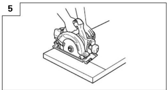
Place the wider portion of the saw base on that part of the work piece which is solidly supported, not on the section that will fall off when the cut is made. As examples, Fig. 5 illustrates the RIGHT way to cut off the end of board, and Fig. 6 the WRONG way. If the work piece is short or small, clamp is down.
DON'T TRY TO HOLD SHORT PLACES BY HAND!
-
Never attempt to saw with the circular saw held upside down in a vise. This is extremely dangerous and can lead to serious accidents (Fig. 7).
-
When the brake becomes ineffective, replace the carbon brushes with new ones.
CAUTION ON LITHIUM-ION BATTERY
To extend the lifetime, the lithium-ion battery equips with the protection function to stop the output.
In the cases of 1 and 2 described below, when using this product, even if you are pulling the switch, the motor may stop. This is not the trouble but the result of protection function.
- When the battery power remaining runs out (The battery voltage drops to about 12V (C18DL)), the motor stops.
In such case, charge it up immediately. 2. If the tool is overloaded, the motor may stop. In this case, release the switch of tool and eliminate causes of overloading. After that, you can use it again.
SPECIFICATIONS
Power Tool
| Model C18DMR C18DL | ||||
| No-load speed 3400 min | -1 | |||
| Capacity Cutting depth 90° | 57 mm | |||
| 45° | 40 mm | |||
| Rechargeable battery | 18 V 2.0 Ah | EB1820L: Ni-Cd (15 cells) | x | |
| 18 V 2.6 Ah | EB1826HL: Ni-MH (15 cells) | x | ||
| 18 V 3.0 Ah | EB1830HL: Ni-MH (15 cells) | EBM1830: Li-ion (10 cells) | ||
| 18 V 3.0 Ah | EB1830X: Ni-MH (15 cells) | x | ||
| 18 V 3.3 Ah | EB1833X: Ni-MH (15 cells) | x | ||
| Light bulb | 12 V, 5 W | |||
| Weight | 3.6 kg | 3.2 kg | ||
Charger
| Model UC24YFA UC18YG UC18YRL | ||||
| Charging voltage 7.2 – 24 V 7.2 – 18 V 7.2 – 18 V | ||||
| Charging time 2.0 Ah : Ni-Cd 50 min. 50 min. 30 min. | ||||
| 2.6 Ah : Ni-MH 65 min. x 40 min. | ||||
| 3.0 Ah : Ni-MH 70 min. x 45 min. | ||||
| 3.3 Ah : Ni-MH 75 min. x 50 min. | ||||
| 3.0 Ah : Li-ion x x 45 min. | ||||
| Weight 0.6 Kg 0.3 Kg 0.6 Kg | ||||
Charge time is approximate. Actual charge time may vary.
“x” Indicates that the battery pack is not compatible with that specific charger.
STANDARD ACCESSORIES
| C18DMRC18DL | 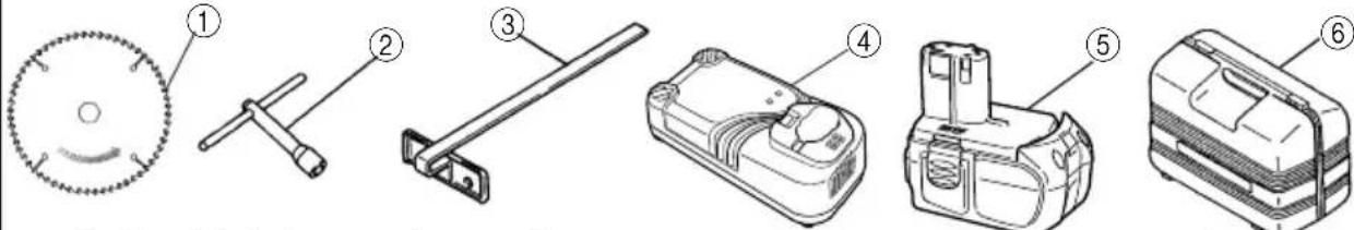 |
| 1 Saw Blade (mounted on tool) .... 12 Box Wrench .... 13 Guide .... 14 Charger (UC24YFA or UC18YG or UC18YRL) .... 15 Battery C18DMR (2BLFK) (2HLFK), C18DL (2MRK) .... 2C18DMR (BLFK) (HLFK), C18DL (MRK) .... 16 Plastic case .... 1 | |
| C18DMR(NN)(For kit) |  |
| 1 Saw Blade (mounted on tool) .... 12 Box Wrench .... 13 Guide .... 1 |
Standard accessories are subject to change without notice.
OPTIONAL ACCESSORIES (sold separately)
- Battery (EB1820L, EB1826HL, EB1830HL, EB1830X, EB1833X, EBM1830)
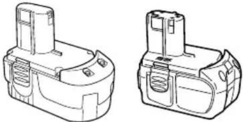
natural_image
Technical line drawings of two battery modules (no text or symbols)- Saw Blade
Use.....Cutting various types of wood.
| External Diam | Hole Diam. No. of | Teeth |
| 165 mm 16 | mm 24 pieces | |
| 165 mm 20 | mm 24 pieces | |
| 165 mm 30 | mm 24 pieces |
-
Washer (A) .... for 16 mm (Hole dia. of saw blade) .... for 20 mm (Hole dia. of saw blade) .... for 30 mm (Hole dia. of saw blade)
-
Dust Collector Set
Connect the suction hose to collect saw dust with the vacuum cleaner (see Fig. 27).
Optional accessories are subject to charge without notice.
APPLICATION
Cutting various types of wood.
BATTERY REMOVAL/INSTALLATION
- Battery removal
Hold the handle tightly and push the battery latches to remove the battery (see Fig. 8, 9).
CAUTION
Never short-circuit the battery.
- Battery installation
Insert the battery while observing its polarities (see Fig. 9).
CHARGING
Before using the power tool, charge the battery as follows.
-
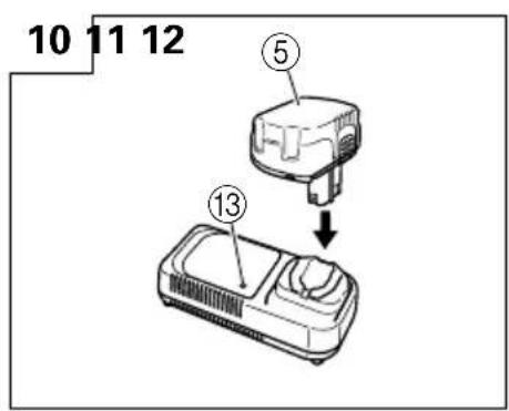
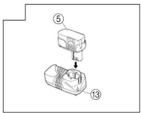
Connect the charger's power cord to a receptacle When the power cord is connected, the charger's pilot lamp will blink in red (At 1-second intervals).
-
Insert the battery into the charger
Insert the battery firmly, until it contacts the bottom of the charger compartment.
CAUTION
○If the battery is inserted in the reverse direction, not only recharging will become impossible, but it may also cause problems in the charger such as deformed recharging terminal.
- Charging
When inserting a battery in the charger, charging will commence and the pilot lamp will light up continuously in red.
When the battery becomes fully recharged, the pilot lamp will blink in red (At 1-second intervals) (See Table 1).
(1) Pilot lamp indication
The indications of the pilot lamp will be as shown in Table 1, according to the condition of the charger or the rechargeable battery.
Table 1
| Indications of the lamps | |||
| Before charging | Blinks (RED) | Lights for 0.5 seconds. Does not light for 0.5 seconds. (off for 0.5 seconds) | |
| While charging | Lights (RED) | Lights continuously | |
| Charging complete | Blinks (RED) | Lights for 0.5 seconds. Does not light for 0.5 seconds. (off for 0.5 seconds) | |
| Charging impossible | Flikers (RED) | Lights for 0.1 seconds. Does not light for 0.1 seconds. (off for 0.1 seconds) | Malfunction in the battery or the charger. |
| Overheat standby | Lights (GREEN) | Lights continuously | Battery overheated. Unable to charge (Charging will commence when battery cools). |
NOTE: When standby for cooling battery, UC18YRL cools the overheated battery by cooling fan.
(2) Regarding the temperatures of the rechargeable battery
The temperatures for rechargeable batteries are as shown in the table below, and batteries that have become hot should be cooled for a while before being recharged.
Table 2 Recharging ranges of batteries
| ChargerRechargeable batteries | UC24YFA UC18YRL | |
| Ni-Cd batteries -5°C - | 55°C | |
| Ni-MH batteries 0°C - | 45°C -5°C -50°C | |
| Li-ion batteries x 0°C + | 50°C | |
4. Disconnect the charger's power cord from the receptacle
5. Hold the charger firmly and pull out the battery NOTE
Be sure to pull out the battery from the charger after use, and then keep it.
CAUTION
○If the battery is charged while it is heated because it has been left for a long time in a location subject to direct sunlight or because the battery has just been used, the pilot lamp of the charger lights up green. In such a case, first let the battery cool, then start charging.
When the pilot lamp flikers in red quickly (at 0.2-second intervals), check for and take out any foreign objects in the charger's battery installation hole. If there are no foreign objects, it is probable that the battery or charger is malfunctioning. Take it to your Authorized Service Center.
○Since the built-in micro computer takes about 3 seconds to confirm that the battery being charged with UC24YFA and UC18YRL are taken out, wait for
a minimum of 3 seconds before reinserting it to continue charging. If the battery is reinserted within 3 seconds, the battery may not be properly charged. (UC18YG)
Before using the power tool, charge the battery as follows.
- Connect the charger power cord to the receptacle Connecting the power cord will turn on the charger.
2. Insert the battery into the charger
Insert the battery firmly while observing its direction, until it contacts the bottom of the charger (the pilot lamp lights up).
CAUTION
If the pilot lamp does not light up, pull out the power cord from the receptacle and check the battery mounting condition.
About 50 minutes is required to fully charge the battery at a temperature of about 20^ C. The pilot lamp goes off to indicate that the battery is fully charged.
The battery charging time becomes longer when a temperature is low or the voltage of the power source is too low.
When the pilot lamp does not go off even if more than 120 minutes have elapsed after starting of the charging, stop the charging and contact your HiKOKI AUTHORIZED SERVICE CENTER.
CAUTION
If the battery is heated due to direct sunlight, etc., just after operation, the charger pilot lamp may not light up. At that time, cool the battery first, then start charging.
3. Disconnect the charger power cord from the receptacle
4. Hold the charger tight and pull out the battery
Regarding electric discharge in case of new batteries, etc.
As the internal chemical substance of new batteries and batteries that have not been used for an extended period is not activated, the electric discharge might be low when using them the first and second time. This is a temporary phenomenon, and normal time required for recharging will be restored by recharging the batteries 2 – 3 times.
How to make the batteries perform longer
(1) Recharge the batteries before they become completely exhausted.
When you feel that the power of the tool becomes weaker, stop using the tool and recharge its battery. If you continue to use the tool and exhaust the electric current, the battery may be damaged and its life will become shorter.
(2) Avoid recharging at high temperatures.
A rechargeable battery will be hot immediately after use. If such a battery is recharged immediately after use, its internal chemical substance will deteriorate, and the battery life will be shortened. Leave the battery and recharge it after it has cooled for a while.
PRIOR TO OPERATION
- Setting up and checking the work environment
Check if the work environment is suitable by following the precautions.
- Prepare a wooden workbench (Fig. 13)
Since the saw blade will extend beyond the lower surface of the lumber, place the lumber on a workbench when cutting. If a square block is utilized as a workbench, select level ground to ensure it is properly stabilized. An unstable workbench will result in hazardous operation.
CAUTION
To avoid possible accident, always ensure that the portion of lumber remaining after cutting is securely anchored or held in position.
ADJUSTING THE SAW PRIOR TO USE
CAUTION
Pull out battery before doing any adjusting.
- Adjusting the cutting depth
As shown in Fig. 14, hold the handle with one hand while loosening the wing nut with the other.
The cutting depth can be adjusted by moving the base to the desired position. In such manner adjust the cutting depth and then securely retighten the wing nut.
- Adjusting the angle of inclination
As shown in Fig. 15 by loosening the wing bolt on the incline gauge, the saw blade may be inclined to a maximum angle of 50^ in relation to the base. After having completed the adjustment, reconfirm that the wing bolt are firmly tightened.
NOTE
Values of the inclined gauge provided on the base merely serve as a rough guideline. For cutting operation at an inclined posture, use the circular saw after adjusting the angle between the base and the saw blade with a protractor, etc.
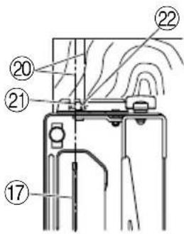
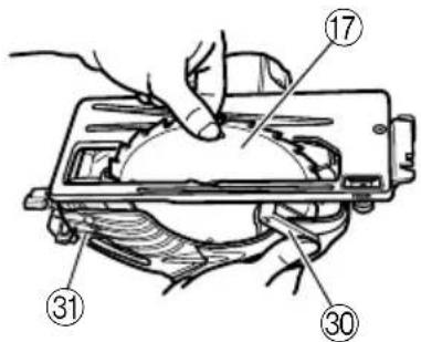
- Regulating the guide (Fig. 17)
The cutting position can be regulated by moving the guide to the left or right after loosening its knob bolt. The guide may be mounted on either the right or left side of the tool.
HOW TO USE
- Operation of switch (Fig. 18) (switch trigger and light switch)
(1) For safe operation of the machine, a "switch lock" is provided on the side of a handle.
If the "switch trigger" is pulled in a state where "switch lock" is pressed in the direction of the arrow mark, the main switch can be turned ON. And the "switch lock" is used as the "light switch". If the "switch lock (light switch)" is pressed in a state, the light is turned ON.
(2) After the switch is turned ON, even when you release your hand from the switch lock, the body continues running and the light continues being turned ON as long as you keep on pulling the switch trigger.
(3) If you release the switch trigger, you can turn OFF the switch and the "switch lock" returns to the original position automatically and the light turns OFF too.
CAUTION
○Do not fix and secure the switch lock. Besides, keep your finger off the switch trigger when the circular saw is being carried around. Otherwise, the main body switch can be inadvertently turned ON, resulting in unexpected accidents.
Keep the light ON during cutting operation only. If it is lit ON in other cases, the main body switch can be inadvertently turned ON, resulting in unexpected accidents.
○If the main body is left as it is with the battery inserted, there can be a case where the [switch lock] touches the floor and/or wall surface and lights up continuously, depending on the direction of the body. Be careful, since continuous lighting can easily make a full-charged battery go dead in about 3 hours.
- Cutting procedures
CAUTION
○Recheck that the saw blade is securely clamped.
○Confirm that the wing nut for adjusting the slot depth, the wing bolt for adjusting the angle of inclination are securely clamped.
(1) Place the base on the material, then align the premarked line and the sawblade with the notch at the front of the base (Fig. 16).
When the base is not slanted, use the large cutout as the guide (Fig. 16, Fig. 19(A)).
If the base is slanted (45 degrees), use the small front scale as the guide (Fig. 16, Fig. 19(B)).
(2) Ensure that the switch is turned to the ON position before the saw blade comes in contact with the lumber. The switch is turned ON when the trigger is squeezed; and OFF when the trigger is released. Moving the saw straight at a constant speed will produce optimum cutting.
CAUTIONS
Before starting to saw, ensure that the saw blade has reached full speed revolution.
○Should the saw blade be stopped or made an abnormal noise during operation, turn off the switch immediately.
When finished with a job, pull out the battery from the main body.
○Twisting and forcibly pressing the saw during cutting can result in unreasonable pressure on the motor, so try to go straight quietly.
○In the situation where the circular saw is continuously operated while replacing the battery with stocked spare batteries one after another, the motor tends to overheat. Therefore, whenever the housing becomes hot, give the saw a break for a while.
○Avoid cutting operation in a state where the base bottom is afloat from the material being cut. Otherwise, the motor can get locked.
MOUNTING AND DISMOUNTING THE SAW BLADE
CAUTION
To avoid serious accident, ensure the switch is in the OFF position, and pull out the battery.
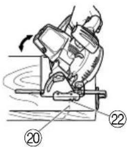
1. Dismounting the saw blade
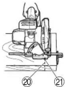
(1) Set the cutting volume at maximum, and place the Circular Saw as shown in Fig. 20.
(2) Depress the lock lever, lock the spindle, and remove the left-hand bolt and washer (B) with the box wrench.
(3) While holding the lower guard lever to keep the lower guard fully retracted into the saw cover, remove the saw blade (Fig. 21).
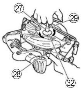
2. Mounting the Saw Blade
CAUTION
If the left-hand bolt is worked using other tools than the provided box wrench, excessive tightening and insufficient tightening may take place resulting in injury.
(1) Thoroughly remove any sawdust which has accumulated on the spindle, bolt and washers.
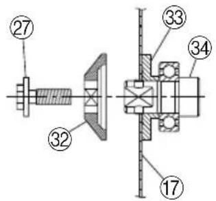
(2) As shown in Fig. 22, the side of Washer (A) with a projected center the same diameter as the inner diameter of the saw blade and the concave side of Washer (B) must be fitted to the saw blade sides.
* Washer (A) is supplied for 2 types of saw blades with the hole diameters of 16 mm and 30 mm. (When buying the Circular Saw, one type of washer (A) is applied.) In case the hole diameter of your saw blade does not correspond to that of washer (A), please contact the shop where you purchased the Circular Saw.
(3) To assure proper rotation direction of the saw blade, the arrow direction on the saw blade must coincide with the arrow direction on the saw cover.
(4) Using the fingers, tighten the left-hand bolt retaining the saw blade as much as possible. Then depress the lock lever, lock the spindle, and thoroughly tighten the left-hand bolt.
CAUTION
After having attached the saw blade, reconfirm that the lock lever is firmly secured in the prescribed position.
REPLACING LIGHT BULB
CAUTION
○Make absolutely sure that the battery is removed from the main body before replacing the light bulb.
○Immediately after the light is turned OFF, the bulb retains high temperature. Make sure to cool down the light bulb thoroughly before replacing it so as to prevent burns.
When replacing the light bulb, check the shape of base as well as the rating (12 V, 5 W), and then carry out perfect mounting. Otherwise, the light bulb can come off and/or cause overheat.
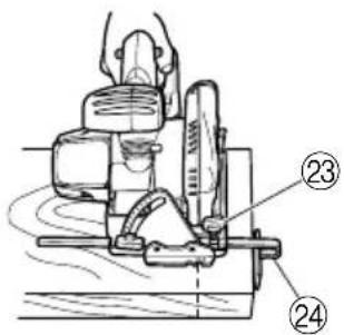
1. Detaching light bulb
(1) Remove the convex part of the light cover from the concave part of the handle cover, and then pull out the light cover in the arrow-marked direction as shown in Fig. 23.
(2) Push the back of the socket, and remove the socket and the light bulb together from the handle cover (Fig. 24).
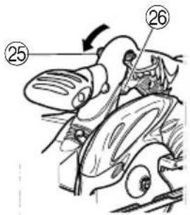
(3) Remove the light bulb from the socket (Fig. 25).
2. Attaching light bulb
Take procedures here that are contrary to the detaching procedures.
NOTE
○When attaching the light bulb to the socket, insert the light bulb until it lightly bumps against the socket.
When attaching the socket to the handle cover, align the socket with the hole of housing while watching the back of the socket shown in Fig. 25, and insert the socket until it lightly bumps against the handle cover.
MAINTENANCE AND INSPECTION
CAUTION
Pull out battery before doing any inspection or maintenance.
1. Inspecting the saw blade
Since use of a dull saw blade will degrade efficiency and cause possible motor malfunction, sharpen or replace the saw blade as soon as abrasion is noted.
CAUTION
If a dull saw blade is used, reactive force is increased during cutting operation. Avoid the use of the dull saw blade without repair.
2. Inspecting the mounting screws
Regularly inspect all mounting screws and ensure that they are properly tightened. Should any of the screws be loose, retighten them immediately. Failure to do so could result in serious hazard.
3. Maintenance of the motor
The motor unit winding is the very "heart" of the power tool.
Exercise due care to ensure the winding does not become damaged and/or wet with oil or water.
4. Performance checkup and maintenance of lower guard
Keep the lower guard in good shape for smooth performance at all times. Be sure to make prompt repair in case of any malfunction.
For safe and proper working, always keep the machine and ventilation slots clean. The lower guard must always be able to more freely and retract
automatically. Therefore, always keep the area around the lower guard clean. Remove dust and chips by blowing out with compressed air or with a brush.
5. Adjusting the base and saw blade to maintain perpendicularity
The angle between the base and the saw blade has been adjusted to 90^ , however should this perpendicularity be lost for some reason, adjust in the following manner:
(1) Turn the base face up (Fig. 26) and loosen the wing-bolt.
(2) Apply a square to the base and the saw blade and turning the slotted set screw with a slotted-head screwdriver, shift the position of the base to produce the desired right angle.
6. Check for dust
Dust may be removed with a clean rag or a cloth dampened with soapy water.
Do not use bleach, chlorine, gasoline or thinner, for they may damage the plastics.
7. Storage
Storing in a place below 40^ C and out of the reach of children.
NOTE
Make sure that the battery is fully charged when stored for a long period (3 months or more). The battery with smaller capacity may not be able to be charged when used, if stored for a long period.
NOTE
Storing lithium-ion batteries
Make sure the lithium-ion batteries have been fully charged before storing them.
Prolonged storage of batteries with a low charge may result in performance deterioration, significantly reducing battery usage time or rendering the batteries incapable of holding a charge.
However, significantly reduced battery usage time may be recovered by repeatedly charging and using the batteries two to five times.
If the battery usage time is extremely short despite repeated charging and use, consider the batteries dead and purchase new batteries.
8. Service and repairs
All quality power tools will eventually require servicing or replacement of parts because of wear from normal use. To assure that only genuine replacement parts must be used, all service and repairs must be performed by a HiKOKI AUTHORIZED SERVICE CENTER, ONLY.
9. Service parts list
CAUTION
Repair, modification and inspection of HiKOKI Power Tools must be carried out by a HiKOKI Authorized Service Center.
This Parts List will be helpful if presented with the tool to the HiKOKI Authorized Service Center when requesting repair or other maintenance.
In the operation and maintenance of power tools, the safety regulations and standards prescribed in each country must be observed.
MODIFICATIONS
HiKOKI Power Tools are constantly being improved and modified to incorporate the latest technological advancements.
Accordingly, some parts may be changed without prior notice.
GUARANTEE
We guarantee HiKOKI Power Tools in accordance with statutory/country specific regulation. This guarantee does not cover defects or damage due to misuse, abuse, or normal wear and tear. In case of complaint, please send the Power Tool, undismantled, with the GUARANTEE CERTIFICATE found at the end of this Handling instruction, to a HiKOKI Authorized Service Center.
NOTE
Due to HiKOKI's continuing program of research and development, the specifications herein are subject to change without prior notice.
IMPORTANT
Correct connection of the plug
The wires of the main lead are coloured in accordance with the following code:
Blue: - Neutral
Brown: - Live
As the colours of the wires in the main lead of this tool may not correspond with the coloured markings identifying the terminals in your plug proceed as follows: The wire coloured blue must be connected to the terminal marked with the letter N or coloured black.
The wire coloured brown must be connected to the terminal marked with the letter L or coloured red.
Neither core must be connected to the earth terminal.
NOTE
This requirement is provided according to BRITISH STANDARD 2769: 1984.
Therefore, the letter code and colour code may not be applicable to other markets except The United Kingdom.
Information concerning airborne noise and vibration The measured values were determined according to EN60745 and declared in accordance with ISO 4871.
Measured A-weighted sound power level: 106 dB (A). Measured A-weighted sound pressure level: 95 dB (A). Uncertainty KpA: 3 dB (A).
Wear ear protection.
Vibration total values (triax vector sum) determined according to EN60745.
Vibration emission value a_h = 1.4 m/s^2
Uncertainty K = 1.5 m/s ^4
The declared vibration total value has been measured in accordance with a standard test method and may be used for comparing one tool with another.
It may also be used in a preliminary assessment of exposure.
WARNING
○The vibration emission during actual use of the power tool can differ from the declared total value depending on the ways in which the tool is used.
○Identify safety measures to protect the operator that are based on an estimation of exposure in the actual conditions of use (taking account of all parts of the operating cycle such as the times when the tool is switched off and when it is running idle in addition to the trigger time). 16
natural_image
Technical line drawings of two battery modules (no text or symbols)- Sägeblatt
natural_image
Technical line drawings of two battery modules (no text or symbols)natural_image
Technical line drawings of two battery modules (no text or symbols)VEILIGHEIDSWAARSCHUWINGEN VOOR DE CIRKELZAAGMACHINE
Zaagprocedures
natural_image
Technical line drawings of two battery modules (no text or symbols)- Zaagblad
natural_image
Technical line drawings of two battery modules (no text or symbols)natural_image
Technical line drawings of two battery modules (no text or symbols)natural_image
Technical line drawings of two battery modules (no text or symbols)- Πριονωτή λεπίδα
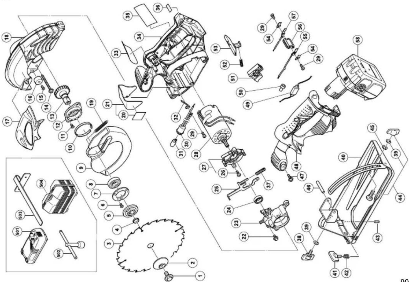
C18DL
| Item No. | Part Name |
| 49 | RESISTOR (A) |
| 50 | CONNECTOR |
| 51 | SWITCH |
| 52 | SPRING (F) |
| 53 | KNOB |
| 54 | HOLDER SPRING |
| 55 | TERMINAL |
| 56 | TERMINAL PIECE |
| 57 | TERMINAL |
| 58 | BATTERY (EBM1830) |
| 501 | CHARGER (UC18YRL) |
| 502 | BOX WRENCH |
| 503 | GUIDE |
| 504 | CASE |
| Item No. | Part Name |
| 1 BOLT (W/WASHER) M7×17.5 | |
| 2 WASHER (B2) | |
| 3 TCT SAW BLADE 165MM-15.9 | |
| 4 RING D15.9/I. D14.5 | |
| 5 WASHER (A1) | |
| 6 SEAR LOCK FLAT HD. SCREW M3×12 | |
| 7 BEARING COVER | |
| 8 BALL BEARING 6002VVCMPS2L | |
| 9 LOWER GUARD | |
| 10 BUSHING | |
| 11 SEAL LOCK FLAT HD. SCREW M5×12 | |
| 12 BEARING HOLDER | |
| 13 GEAR | |
| 14 TAPPING SCREW (W/FLANGE) D5×50 | |
| 15 FLAT HD. SCREW M5×20 | |
| 16 CUSHION | |
| 17 BRAND PLATE | |
| 18 SAW COVER | |
| 19 RETURN SPRING | |
| 20 LABEL (LC) | |
| 21 LIGHT COVER ASS'Y | |
| 22 NYLOCK BOLT (W/FLANGE) M4×12 | |
| 23 INNER COVER (B) | |
| 24 BALL BEARING 609VVC2PS2L | |
| 25 LOCK LEVER | |
| 26 SPECIAL BOLT M5 | |
| 27 INNER COVER (A) ASS'Y | |
| 28 MOTOR (B) | |
| 29 TAPPING SCREW D4×10 | |
| 30 SOCKET | |
| 31 LIGHT | |
| 32 TERMINAL (D) | |
| 33 NAMEPLATE | |
| 34 HOUSING | |
| 35 CAUTION PLATE | |
| 36 CAUTION PLATE | |
| 37 SPRING | |
| 38 WING BOLT (A) | |
| 39 SUPER LOCK WASHER M6 | |
| 40 BASE ASS'Y | |
| 41 KNOB BOLT | |
| 42 LOCK SPRING | |
| 43 SLOTTED HD. SET SCREW (SEAL LOCK) M6×6 | |
| 44 BOLT ASS'Y (SQUARE) M2×22 | |
| 45 WASHER M6 | |
| 46 ROLL PIN D6×50 | |
| 47 TAPPING SCREW (W/FLANGE) D4×16 | |
| 48 HANDLE COVER | |
natural_image
Line drawing of a quill pen with inkwell (no text or symbols)| English | Nederlands | ||
| GUARANTEE CERTIFICATE1Model No.2Serial No.3Date of Purchase4Customer Name and Address5Dealer Name and Address(Please stamp dealer name and address) | GARANTIEBEWIJS1Modelnummer2Serienummer3Datum van aankoop4Naam en adres van de gebruiker5Naam en adres van de handelaar(Stempel a.u.b. naam en adres vande de handelaar) | ||
| Deutsch | GARANTIESCHEIN1Modell-Nr.2Serien-Nr.3Kaufdaturn4Name und Anschrift des Kunden5Name und Anschrift des Händlers(Bitte mit Namen und Anschrift des Handlers abstempeln) | Español | |
| CERTIFICADO DE GARANTIA1Número de modelo2Número de serie3Fecha de adquisición4Nombre y dirección del cliente5Nombre y dirección del distribudor(Se ruega poner el sellú del distribudor con su nombre y dirección) | |||
| Français Português | |||
| CERTIFICAT DE GARANTIE1No. de modèle2No. de série3Date d'achat4Nom et adresse du client5Nom et adresse du revendeur(Cachet portant le nom et l'adresse du revendeur) | CERTIFICADO DE GARANTIA1Número do modelo2Número do série3Data de compra4Nome e morada do cliente5Nome e morada do distribuidor(Por favor, carímbe o nome e morada do distribuidor) | ||
| Italiano Ελληνικά | |||
| CERTIFICATO DI GARANZIA1Modello2N° di serie3Data di acquisto4Nome e indirizzo dell'acquirente5Nome e indirizzo del rivenditore(Si prega di apporre il timbro con questi dati) | ΠΙΣΤΟΠΟΙΗΤΙΚΟ ΕΓΓΥΗΣΗΣ1Αρ. Μοντέλου2Αύξων Αρ.3Ημερομηνία αγοράς4Όνομα και διεύθυνση πελάτη5Όνομα και διεύθυνση μεταπωλητή(Παρακαλούμε να χρησιμοποιηθεί σφραγίδα) | ||
HiKOKI
| 1 | |
| 2 | |
| 3 | |
| 4 | |
| 5 |
Siemensring 34, 47877 willich, Germany
Tel: +49 2154 49930
Fax: +49 2154 499350
URL: http://www.hikoki-powertools.de
Hikoki Power Tools Netherlands B.V.
Brabanthaven 11, 3433 PJ Nieuwegein, The Netherlands
Tel: +31 30 6084040
Fax: +31 30 6067266
URL: http://www.hikoki-powertools.nl
Hikoki Power Tools (U.K.) Ltd.
Precedent Drive, Rooksley, Milton Keynes, MK 13, 8PJ,
United Kingdom
Tel: +44 1908 660663
Fax: +44 1908 606642
URL: http://www.hikoki-powertools.uk
Hikoki Power Tools France S.A.S.
Hikoki Power Tools Belgium N.V./S.A.
Koningin Astridlaan 51, B-1780 Wemmel, Belgium
Tel: +32 2 460 1720
Fax: +32 2 460 2542
URL http://www.hikoki-powertools.be
Hikoki Power Tools Italia S.p.A
Via Piave 35, 36077, Altavilla Vicentina (VI), Italy
Tel: +39 0444 548111
Fax: +39 0444 548110
URL: http://www.hikoki-powertools.it
Hikoki Power Tools Ibérica, S.A.
C/ Puigbarral, 26-28, Pol. Ind. Can Petit, 08227 Terrassa
(Barcelona), Spain
Tel: +34 93 735 6722
Fax: +34 93 735 7442
URL: http://www.hikoki-powertools.es
- Save all warnings and instructions for future reference.
- 1) Work area safety
- 2) Electrical safety
- 3) Personal safety
- 4) Power tool use and care
- PRECAUTION
- CIRCULAR SAW SAFETY WARNINGS
- Cutting procedures
- Kickback causes and related warnings
- Lower guard function
- PRECAUTIONS ON USING CORDLESS CIRCULAR SAW
- CAUTION ON LITHIUM-ION BATTERY
- SPECIFICATIONS
- STANDARD ACCESSORIES
- OPTIONAL ACCESSORIES (sold separately)
- APPLICATION
- BATTERY REMOVAL/INSTALLATION
- CHARGING
- Pilot lamp indication
- Regarding the temperatures of the rechargeable battery
- Disconnect the charger's power cord from the receptacle
- Hold the charger firmly and pull out the battery NOTE
- CAUTION
- Insert the battery into the charger
- Disconnect the charger power cord from the receptacle
- Hold the charger tight and pull out the battery
- How to make the batteries perform longer
- PRIOR TO OPERATION
- ADJUSTING THE SAW PRIOR TO USE
- HOW TO USE
- CAUTIONS
- MOUNTING AND DISMOUNTING THE SAW BLADE
- Dismounting the saw blade
- Mounting the Saw Blade
- REPLACING LIGHT BULB
- Detaching light bulb
- Attaching light bulb
- NOTE
- MAINTENANCE AND INSPECTION
- Inspecting the saw blade
- Inspecting the mounting screws
- Maintenance of the motor
- Performance checkup and maintenance of lower guard
- Adjusting the base and saw blade to maintain perpendicularity
- Check for dust
- Storage
- Service and repairs
- Service parts list
- MODIFICATIONS
- GUARANTEE
- IMPORTANT
- WARNING
- VEILIGHEIDSWAARSCHUWINGEN VOOR DE CIRKELZAAGMACHINE
- Zaagprocedures
- HiKOKI
- Hikoki Power Tools Netherlands B.V.
- Hikoki Power Tools (U.K.) Ltd.
- Hikoki Power Tools France S.A.S.
- Hikoki Power Tools Belgium N.V./S.A.
- Hikoki Power Tools Italia S.p.A
- Hikoki Power Tools Ibérica, S.A.
Brand : HiKOKI
Model : C18DMR
Category : Saw