
C3606DB - Saw HiKOKI - Free user manual and instructions
Find the device manual for free C3606DB HiKOKI in PDF.
| Brand | HiKOKI |
| Model | C3606DB |
| Product type | Cordless circular saw |
| Power source | 36 V lithium-ion battery (multi-volt type) |
| Weight | 3.4 kg (with BSL36A18) / 3.7 kg (with BSL36B18) |
| No-load speed | 5600 min⁻¹ (high mode), 4300 min⁻¹ (medium mode), 2000 min⁻¹ (silent mode) |
| Max. cutting depth | 66 mm at 90°, 45 mm at 45°, 57 mm at -5° |
| Blade diameter | 165 mm to 162 mm |
| Main functions | Straight cut, bevel cut (0-45°), plunge cut, electric brake, mode change (high/medium/silent), LED light, battery charge indicator |
| Safety | Spring-loaded lower guard, switch lock, overload and overheat protection, electric brake |
| Maintenance and cleaning | Regular cleaning of the blade, lower guard, and ventilation slots; inspection of screws and terminals |
| Spare parts and repairability | Saw blade, guide, battery, charger, hex wrench; repair by HiKOKI authorized service center |
| Warranty | Complies with statutory/national regulations; does not cover normal wear or misuse |
Frequently Asked Questions - C3606DB HiKOKI
User questions about C3606DB HiKOKI
0 question about this device. Answer the ones you know or ask your own.
Ask a new question about this device
Download the instructions for your Saw in PDF format for free! Find your manual C3606DB - HiKOKI and take your electronic device back in hand. On this page are published all the documents necessary for the use of your device. C3606DB by HiKOKI.
USER MANUAL C3606DB HiKOKI
natural_image
Technical line drawing of a mechanical assembly with no visible text or symbols
en Handling instructions
de Bedienungsanleitung
fr Mode d'emploi
it Istruzioni per l'uso
nl Gebruiksaanwijzing
es Instrucciones de manejo
pt Instruções de uso
sv Bruksanvisning
da Brugsanvisning
no Bruksanvisning
fi Käyttöohjeet
el Οδηγίες χειρισμού
pl Instrukcja obsługi
hu Kezelési utasítás
cs Návod k obsluze
tr Kullanım talimatları
ro Instructiuni de utilizare
sl Navodila za rokovanje
sk Pokyny na manipuláciu
bg Инструкция за експлоатация
sr Uputstvo za rukovanje
hr Upute za rukovanje
1
2
natural_image
Line drawing of a hand operating a machine on a workbench (no text or symbols)3
4
natural_image
Technical line drawing of a mechanical assembly with hands operating a workpiece (no text or symbols visible)5
natural_image
Illustration of hands assembling electronic components on a workbench with a clamp (no text or symbols)6
natural_image
Line drawing of hands assembling a mechanical component on a base (no text or symbols)7
natural_image
Illustration of a hand holding a device with a circular symbol and diagonal line, no text or symbols present8
natural_image
Technical line drawing of a mechanical device with no visible text or symbols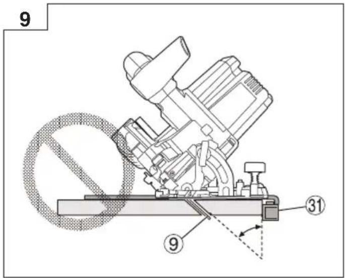
flowchart
graph TD
    A["1: Fan"] --> B["2: Rotation"]
    B --> C["3: Rotation"]
    C --> D["4: Rotation"]
    D --> E["5: Rotation"]
    E --> F["6: Rotation"]
    F --> G["7: Rotation"]
    G --> H["8: Rotation"]
    H --> I["9: Rotation"]
    I --> J["10: Rotation"]
    style A fill:#f9f,stroke:#333
    style B fill:#ccf,stroke:#333
    style C fill:#cfc,stroke:#333
    style D fill:#fcc,stroke:#333
    style E fill:#cff,stroke:#333
    style F fill:#ffc,stroke:#333
    style G fill:#cfc,stroke:#333
    style H fill:#fcc,stroke:#333
    style I fill:#cfc,stroke:#333
    style J fill:#fcc,stroke:#333
flowchart
graph TD
    A["Component 1"] --> B["Component 2"]
    B --> C["Component 3"]
    C --> D["Component 4"]
    D --> E["Component 5"]
    E --> F["Component 6"]
    F --> G["Component 7"]
    G --> H["Component 8"]
    H --> I["Component 9"]
    I --> J["Component 10"]
    J --> K["Component 11"]
    K --> L["Component 12"]
    L --> M["Component 13"]
    M --> N["Component 14"]
    N --> O["Component 15"]
    O --> P["Component 16"]
    P --> Q["Component 17"]
    Q --> R["Component 18"]
    R --> S["Component 19"]
    S --> T["Component 20"]
    T --> U["Component 21"]
    U --> V["Component 22"]
    V --> W["Component 23"]
    W --> X["Component 24"]
14 15

16 17
1 + 2 = I
18
flowchart
graph TD
    A["High mode"] --> B["Medium mode"]
    B --> C["Silent mode"]
    D["MODE 2"] --> E["High"]
    F["Silent"] --> G["High"]
    H["27"] --> I["26"]
19
flowchart
graph TD
    A["Start"] --> B{D}
    B --> C{D}
    C --> D["MODE"]
    D --> E["Medium"]
    D --> F["High"]
    D --> G["Silent"]
    style A fill:#f9f,stroke:#333
    style C fill:#f9f,stroke:#333
    style D fill:#ccf,stroke:#333
    style E fill:#dfd,stroke:#333
    style F fill:#dfd,stroke:#333
    style G fill:#dfd,stroke:#333
25
26
27


28
29
30 31
natural_image
Diagram of a medical device with a plug inserted into a device, connected to a wall-mounted device (no text or symbols visible)a
b
32 33
GENERAL POWER TOOL SAFETY WARNINGS

WARNING
Read all safety warnings, instructions, illustrations and specifications provided with this power tool.
Failure to follow all instructions listed below may result in electric shock, fi re and/or serious injury.
Save all warnings and instructions for future reference.
The term “power tool” in the warnings refers to your mains-operated (corded) power tool or battery-operated (cordless) power tool.
1) Work area safety
a) Keep work area clean and well lit. Cluttered or dark areas invite accidents
b) Do not operate power tools in explosive atmospheres, such as in the presence of fl ammable liquids, gases or dust.
Power tools create sparks which may ignite the dust or fumes.
c) Keep children and bystanders away while operating a power tool.
Distractions can cause you to lose control.
2) Electrical safety
a) Power tool plugs must match the outlet. Never modify the plug in any way. Do not use any adapter plugs with earthed (grounded) power tools.
Unmodified plugs and matching outlets will reduce risk of electric shock.
b) Avoid body contact with earthed or grounded surfaces, such as pipes, radiators, ranges and refrigerators.
There is an increased risk of electric shock if your body is earthed or grounded.
c) Do not expose power tools to rain or wet conditions.
Water entering a power tool will increase the risk of electric shock.
d) Do not abuse the cord. Never use the cord for carrying, pulling or unplugging the power tool.
Keep cord away from heat, oil, sharp edges or moving parts.
Damaged or entangled cords increase the risk of electric shock.
e) When operating a power tool outdoors, use an extension cord suitable for outdoor use.
Use of a cord suitable for outdoor use reduces the risk of electric shock.
f) If operating a power tool in a damp location is unavoidable, use a residual current device (RCD) protected supply.
Use of an RCD reduces the risk of electric shock.
3) Personal safety
a) Stay alert, watch what you are doing and use common sense when operating a power tool. Do not use a power tool while you are tired or under the influence of drugs, alcohol or medication.
A moment of inattention while operating power tools may result in serious personal injury.
b) Use personal protective equipment. Always wear eye protection.
Protective equipment such as a dust mask, non-skid safety shoes, hard hat or hearing protection used for appropriate conditions will reduce personal injuries.
c) Prevent unintentional starting. Ensure the switch is in the off -position before connecting to power source and/or battery pack, picking up or carrying the tool.
Carrying power tools with your fi nger on the switch or energising power tools that have the switch on invites accidents.
d) Remove any adjusting key or wrench before turning the power tool on.
A wrench or a key left attached to a rotating part of the power tool may result in personal injury.
e) Do not overreach. Keep proper footing and balance at all times.
This enables better control of the power tool in unexpected situations.
f) Dress properly. Do not wear loose clothing or jewellery. Keep your hair and clothing away from moving parts.
Loose clothes, jewellery or long hair can be caught in moving parts.
g) If devices are provided for the connection of dust extraction and collection facilities, ensure these are connected and properly used.
Use of dust collection can reduce dust-related hazards.
h) Do not let familiarity gained from frequent use of tools allow you to become complacent and ignore tool safety principles.
A careless action can cause severe injury within a fraction of a second.
4) Power tool use and care
a) Do not force the power tool. Use the correct power tool for your application.
The correct power tool will do the job better and safer at the rate for which it was designed.
b) Do not use the power tool if the switch does not turn it on and off. Any power tool that cannot be controlled with the switch is dangerous and must be repaired.
c) Disconnect the plug from the power source and/or remove the battery pack, if detachable, from the power tool before making any adjustments, changing accessories, or storing power tools.
Such preventive safety measures reduce the risk of starting the power tool accidentally.
d) Store idle power tools out of the reach of children and do not allow persons unfamiliar with the power tool or these instructions to operate the power tool.
Power tools are dangerous in the hands of untrained users.
e) Maintain power tools and accessories. Check for misalignment or binding of moving parts, breakage of parts and any other condition that may affect the power tool's operation. If damaged, have the power tool repaired before use.
Many accidents are caused by poorly maintained power tools.
f) Keep cutting tools sharp and clean.
Properly maintained cutting tools with sharp cutting edges are less likely to bind and are easier to control.
g) Use the power tool, accessories and tool bits etc. in accordance with these instructions, taking into account the working conditions and the work to be performed.
Use of the power tool for operations different from those intended could result in a hazardous situation.
h) Keep handles and grasping surfaces dry, clean and free from oil and grease.
Slippery handles and grasping surfaces do not allow for safe handling and control of the tool in unexpected situations.
5) Battery tool use and care
a) Recharge only with the charger specified by the manufacturer.
A charger that is suitable for one type of battery pack may create a risk of fi re when used with another battery pack.
b) Use power tools only with specifically designated battery packs.
Use of any other battery packs may create a risk of injury and fire.
c) When battery pack is not in use, keep it away from other metal objects, like paper clips, coins, keys, nails, screws or other small metal objects, that can make a connection from one terminal to another.
Shorting the battery terminals together may cause burns or a fire.
d) Under abusive conditions, liquid may be ejected from the battery; avoid contact. If contact accidentally occurs, fl ush with water. If liquid contacts eyes, additionally seek medical help.
Liquid ejected from the battery may cause irritation or burns.
e) Do not use a battery pack or tool that is damaged or modified.
Damaged or modified batteries may exhibit unpredictable behaviour resulting in fire, explosion or risk of injury.
f) Do not expose a battery pack or tool to fire or excessive temperature.
Exposure to fire or temperature above 130^ C may cause explosion.
g) Follow all charging instructions and do not charge the battery pack or tool outside the temperature range specified in the instructions.
Charging improperly or at temperatures outside the specific range may damage the battery and increase the risk of fire.
6) Service
a) Have your power tool serviced by a qualified repair person using only identical replacement parts.
This will ensure that the safety of the power tool is maintained.
b) Never service damaged battery packs. Service of battery packs should only be performed by the manufacturer or authorized service providers.
PRECAUTION
Keep children and infi rm persons away. When not in use, tools should be stored out of reach of children and infi rm persons.
CORDLESS CIRCULAR SAW SAFETY WARNINGS
Cutting procedures
a) ⚠️ DANGER: Keep hands away from cutting area and the blade. Keep your second hand on auxiliary handle, or motor housing.
If both hands are holding the saw, they cannot be cut by the blade.
b) Do not reach underneath the workpiece.
The guard cannot protect you from the blade below the workpiece.
c) Adjust the cutting depth to the thickness of the workpiece.
Less than a full tooth of the blade teeth should be visible below the workpiece.
d) Never hold the workpiece in your hands or across your leg while cutting. Secure the workpiece to a stable platform.
It is important to support the work properly to minimize body exposure, blade binding, or loss of control.
e) Hold the power tool by insulated gripping surfaces, when performing an operation where the cutting tool may contact hidden wiring or its own cord.
Contact with a “live” wire will also make exposed metal parts of the power tool “live” and could give the operator an electric shock.
f) When ripping, always use a rip fence or straight edge guide.
This improves the accuracy of cut and reduces the chance of blade binding.
g) Always use blades with correct size and shape (diamond versus round) of arbour holes.
Blades that do not match the mounting hardware of the saw will run off -centre, causing loss of control.
h) Never use damaged or incorrect blade washers or bolt.
The blade washers and bolt were specially designed for your saw, for optimum performance and safety of operation.
Kickback causes and related warnings
it^- kickback is a sudden reaction to a pinched, jammed or misaligned saw blade, causing an uncontrolled saw to lift up and out of the workpiece toward the operator;
- when the blade is pinched or jammed tightly by the kerf closing down, the blade stalls and the motor reaction drives the unit rapidly back toward the operator;
may if the blade becomes twisted or misaligned in the cut, the teeth at the back edge of the blade can dig into the top surface of the wood causing the blade to climb out of the kerf and jump back toward the operator.
Kickback is the result of saw misuse and/or incorrect operating procedures or conditions and can be avoided by taking proper precautions as given below.
a) Maintain a fi rm grip with both hands on the saw and position your arms to resist kickback forces. Position your body to either side of the blade, but not in line with the blade.
Kickback could cause the saw to jump backwards, but kickback forces can be controlled by the operator, if proper precautions are taken.
b) When blade is binding, or when interrupting a cut for any reason, release the trigger and hold the saw motionless in the material until the blade comes to a complete stop.
Never attempt to remove the saw from the work or pull the saw backward while the blade is in motion or kickback may occur.
Investigate and take corrective actions to eliminate the cause of blade binding.
c) When restarting a saw in the workpiece, centre the saw blade in the kerf so that the saw teeth are not engaged into the material.
If a saw blade binds, it may walk up or kickback from the workpiece as the saw is restarted.
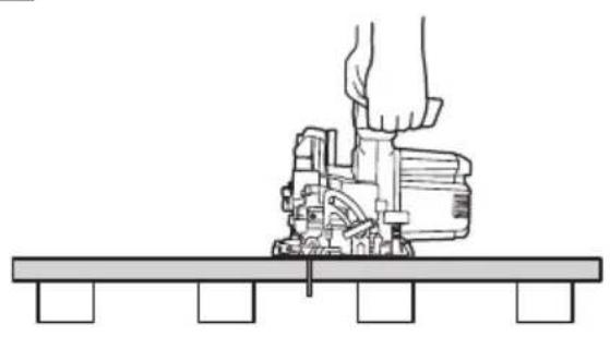
d) Support large panels to minimise the risk of blade pinching and kickback.
Large panels tend to sag under their own weight. Supports must be placed under the panel on both sides, near the line of cut and near the edge of the panel.
English
e) Do not use dull or damaged blades.
Unsharpened or improperly set blades produce narrow kerf causing excessive friction, blade binding and kickback.
f) Blade depth and bevel adjusting locking levers must be tight and secure before making the cut.
If blade adjustment shifts while cutting, it may cause binding and kickback.
g) Use extra caution when sawing into existing walls or other blind areas.
The protruding blade may cut objects that can cause kickback.
Lower guard function
a) Check the lower guard for proper closing before each use. Do not operate the saw if the lower guard does not move freely and close instantly. Never clamp or tie the lower guard into the open position.
If the saw is accidentally dropped, the lower guard may be bent. Raise the lower guard with the retracting handle and make sure it moves freely and does not touch the blade or any other part, in all angles and depths of cut.
b) Check the operation of the lower guard spring. If the guard and the spring are not operating properly, they must be serviced before use.
Lower guard may operate sluggishly due to damaged parts, gummy deposits, or a build-up of debris.
c) The lower guard may be retracted manually only for special cuts such as "plunge cuts" and "compound cuts". Raise the lower guard by the retracting handle and as soon as the blade enters the material, the lower guard must be released.
For all other sawing, the lower guard should operate automatically.
d) Always observe that the lower guard is covering the blade before placing the saw down on bench or floor.
An unprotected, coasting blade will cause the saw to walk backwards, cutting whatever is in its path. Be aware of the time it takes for the blade to stop after switch is released.
ADDITIONAL SAFETY WARNINGS
-
Wear earplugs to protect your ears during operation.
-
Use only blade diameter specified on the machine.
-
Do not use any abrasive wheel.
-
Do not use saw blades which are deformed or cracked.
-
Do not use saw blades made of high speed steel.
-
Do not use saw blades which do not comply with the characteristics specified in these instructions.
-
Do not stop the saw blades by lateral pressure on the disc.
-
Always keep the saw blades sharp.
-
Ensure that the lower guard moves smoothly and freely.
-
Never use the circular saw with its lower guard fixed in the open position.
-
Ensure that the retraction mechanism of the guard system operates correctly.
-
Never operate the circular saw with the saw blade turned upward or to the side.
-
Ensure that the material is free of foreign matters such as nails.
-
The saw blades range should be from 165 mm to 162 mm.
-
Pull out battery before carrying out any adjustment, servicing or maintenance.
-
Be careful of brake kickback.
This circular saw features an electric brake that functions when the switch is released. As there is some kickback when the brake functions, be sure to hold the main body securely.
-
Ensure that the switch is in the OFF position. If the battery installed to power tool while the switch is in the ON position, the power tool will start operating immediately, which could cause a serious accident.
-
Avoid cutting in the state where the base has floated up from the material.
When blade is binding, or when interrupting a cut for any reason, release the trigger and hold the saw motionless in the material until the blade comes to a complete stop. Never attempt to remove the saw from the work or pull the saw backward while the blade is in motion or KICKBACK may occur. Investigate and take corrective actions to eliminate the cause of blade binding.
- Support large panels to minimize the risk of blade pinching and KICKBACK. Large panels tend to sag under their own weight (Fig. 3). Supports must be placed under the panel on both sides, near the line of cut and near the edge of the panel as shown in Fig. 2.
To minimize the risk of blade pinching and kickback. When cutting operation requires the resting of the saw on the work piece, the saw shall be rested on the larger portion and the smaller piece cut off.
- Use extra caution when making a "Pocket Cut" into existing walls or other blind areas. The protruding blade may cut objects that can cause KICKBACK.
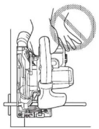
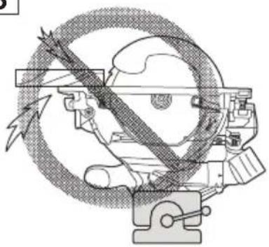
NEVER place your hand or fingers behind the saw (Fig. 4). If kickback occurs, the saw could easily jump backwards over your hand, possibly causing severe injury.
-
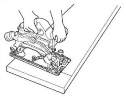
WARNING: It is important to support the work piece properly and to hold the saw fi rmly to prevent loss of control which could cause personal injury. Fig. 5 illustrates typical hand support of the saw.
-
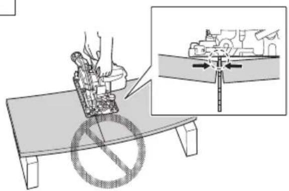
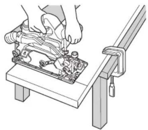
Place the wider portion of the saw base on that part of the work piece which is solidly supported, not on the section that will fall off when the cut is made. As examples, Fig. 6 illustrates the RIGHT way to cut off the end of board, and Fig. 7 the WRONG way. If the work piece is short or small, clamp is down.
ON'T TRY TO HOLD SHORT PLACES BY HAND!
-
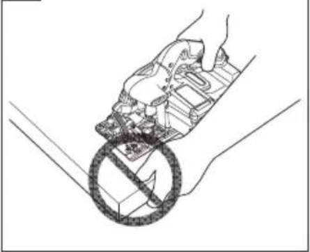
Never attempt to saw with the circular saw held upside down in a vise. This is extremely dangerous and can lead to serious accidents (Fig. 8).
-
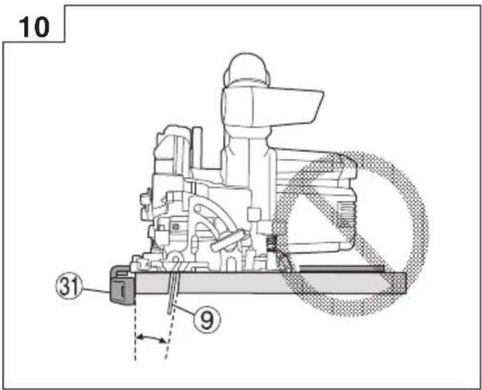
When using the guide, do not attempt an inclined cut which would allow the cut material to slip between the saw blade and guide. Doing so could result in injury. (Fig. 9, 10)
-
Should lever remain loosened, it will create a very hazardous situation. Always thoroughly clamp it. (Fig. 15)
-
It is very hazardous to allow the incline wing bolt and incline wing nut to remain loosened. Always thoroughly clamp it. (Fig. 26)
-
Prior to cutting operation, make sure the material you are going to cut. If the material to be cut is expected to generate harmful / toxic dusts, make sure the dust bag or appropriate dust extraction system is connected with dust outlet tightly.
Wear the dust mask additionally, if available.
Before starting to saw, confirm that the saw blade has attained full-speed revolution.
- Should the saw blade stop or make an abnormal noise while operating, promptly turn OFF the switch.
○ Using the circular saw with the saw blade facing upwards or sideways is very hazardous. Such uncommon applications should be avoided.
○ When cutting materials, always wear protective glasses.
○ When finished with a job, pull out the battery.
-
After having attached the saw blade, reconfirm that the lock lever is firmly secured in the prescribed position.
-
Use a saw blade that is for cutting wood.
-
Use a saw blade with a displayed speed that is equal to or higher than the rotation speed displayed on the tool.
-
Use a saw blade that complies with EN847-1.
-
Do not expose directly your eye to the light by looking into the light.
If your eye is continuously exposed to the light, your eye will be hurt.
Wipe off any dirt or grime attached to the lens of the LED light with a soft cloth, being careful not to scratch the lens.
Scratches on the lens of the LED light can result in decreased brightness.
-
Do not give a strong shock to the switch panel or break it. It may lead to a trouble.
-
Always charge the battery at a temperature of 0^ C– 40^ C. A temperature of less than 0^ C will result in over charging which is dangerous. The battery cannot be charged at a temperature higher than 40^ C.
The most suitable temperature for charging is that of 20^ C– 25^ C.
- Do not use the charger continuously.
When one charging is completed, leave the charger for about 15 minutes before the next charging of battery.
-
Do not allow foreign matter to enter the hole for connecting the rechargeable battery.
-
Never disassemble the rechargeable battery and charger.
-
Never short-circuit the rechargeable battery. Shortcircuiting the battery will cause a great electric current and overheat. It results in burn or damage to the battery.
-
Do not dispose of the battery in fire. If the battery is burnt, it may explode.
-
Bring the battery to the shop from which it was purchased as soon as the post-charging battery life becomes too short for practical use. Do not dispose of the exhausted battery.
-
Do not insert object into the air ventilation slots of the charger. Inserting metal objects or inflammables into the charger air ventilation slots will result in electrical shock hazard or damaged charger.
-
When using this unit continuously, the unit may overheat, leading to damage in the motor and switch. Therefore, whenever the housing becomes hot, give the tool a break for a while.
-
Make sure that the battery is installed firmly. If it is at all loose it could come off and cause an accident.
-
Do not use the product if the tool or the battery terminals (battery mount) are deformed.
Installing the battery could cause a short circuit that could result in smoke emission or ignition.
- Keep the tool's terminals (battery mount) free of swarf and dust.
- Prior to use, make sure that swarf and dust have not collected in the area of the terminals.
During use, try to avoid swarf or dust on the tool from falling on the battery.
When suspending operation or after use, do not leave the tool in an area where it may be exposed to falling swarf or dust.
Doing so could cause a short circuit that could result in smoke emission or ignition.
- Always use the tool and battery at temperatures between -5^ and 40^ .
CAUTION ON LITHIUM-ION BATTERY
To extend the lifetime, the lithium-ion battery equips with the protection function to stop the output.
In the cases of 1 to 3 described below, when using this product, even if you are pulling the switch, the motor may stop. This is not the trouble but the result of protection function.
- When the battery power remaining runs out, the motor stops.
In such a case, charge it up immediately.
-
If the tool is overloaded, the motor may stop. In this case, release the switch of tool and eliminate causes of overloading. After that, you can use it again.
-
If the battery is overheated under overload work, the D battery power may stop.
In this case, stop using the battery and let the battery cool. After that, you can use it again.
Furthermore, please heed the following warning and caution.
WARNING
In order to prevent any battery leakage, heat generation, smoke emission, explosion and ignition beforehand, please be sure to heed the following precautions.
- Make sure that swarf and dust do not collect on the battery.
During work make sure that swarf and dust do not fall on the battery.
○ Make sure that any swarf and dust falling on the power tool during work do not collect on the battery.
○ Do not store an unused battery in a location exposed to swarf and dust.
Before storing a battery, remove any swarf and dust that may adhere to it and do not store it together with metal parts (screws, nails, etc.).
-
Do not pierce battery with a sharp object such as a nail, strike with a hammer, step on, throw or subject the battery to severe physical shock.
-
Do not use an apparently damaged or deformed battery.
-
Do not use the battery for a purpose other than those specified.
-
If the battery charging fails to complete even when a specified recharging time has elapsed, immediately stop further recharging.
-
Do not put or subject the battery to high temperatures or high pressure such as into a microwave oven, dryer, or high pressure container.
-
Keep away from fi re immediately when leakage or foul odor are detected.
-
Do not use in a location where strong static electricity generates.
-
If there is battery leakage, foul odor, heat generated, discolored or deformed, or in any way appears abnormal during use, recharging or storage, immediately remove it from the equipment or battery charger, and stop use.
-
Do not immerse the battery or allow any fluids to flow inside. Conductive liquid ingress, such as water, can cause damage resulting in fi re or explosion. Store your battery in a cool, dry place, away from combustible and fl ammable items. Corrosive gas atmospheres must be avoided.
CAUTION
- If liquid leaking from the battery gets into your eyes, do not rub your eyes and wash them well with fresh clean water such as tap water and contact a doctor immediately.
If left untreated, the liquid may cause eye-problems.
- If liquid leaks onto your skin or clothes, wash well with clean water such as tap water immediately.
There is a possibility that this can cause skin irritation.
- If you find rust, foul odor, overheating, discolor, deformation, and/or other irregularities when using the battery for the first time, do not use and return it to your supplier or vendor.
WARNING
If a conductive foreign matter enters in the terminal of lithium ion battery, the battery may be shorted, causing fire. When storing the lithium ion battery, obey surely the rules of following contents.
○ Do not place conductive debris, nail and wires such as iron wire and copper wire in the storage case.
English
To prevent shorting from occurring, load the battery in the tool or insert securely the battery cover for storing until the ventilator is not seen.
REGARDING LITHIUM-ION BATTERY TRANSPORTATION
When transporting a lithium-ion battery, please observe the following precautions.
WARNING
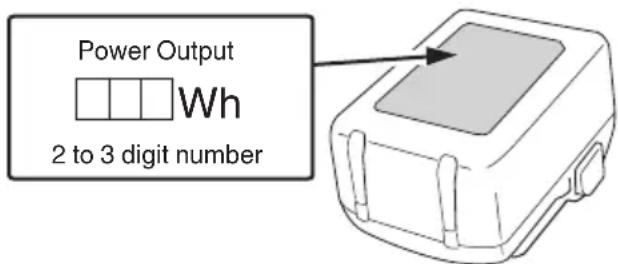
Notify the transporting company that a package contains a lithium-ion battery, inform the company of its power output and follow the instructions of the transportation company when arranging transport.
☐ Lithium-ion batteries that exceed a power output of 100 Wh are considered to be in the freight classification of Dangerous Goods and will require special application procedures.
☐ For transportation abroad, you must comply with international law and the rules and regulations of the destination country.
☐ If the BSL36B18 (sold separately) is installed in the power tool, the power output will exceed 100 Wh and the unit will be classified as Dangerous Goods for freight classification.
USB DEVICE CONNECTION PRECAUTIONS (UC18YSL3)
When an unexpected problem occurs, the data in a USB device connected to this product may be corrupted or lost. Always make sure to back up any data contained in the USB device prior to use with this product.
Please be aware that our company accepts absolutely no responsibility for any data stored in a USB device that is corrupted or lost, nor for any damage that may occur to a connected device.
WARNING
- Prior to use, check the connecting USB cable for any defect or damage.
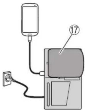
Using a defective or damaged USB cable can cause smoke emission or ignition. - When the product is not being used, cover the USB port with the rubber cover.
Buildup of dust etc. in the USB port can cause smoke emission or ignition.
NOTE
- There may be an occasional pause during USB recharging.
- When a USB device is not being charged, remove the USB device from the charger.
Failure to do so may not only reduce the battery life of a USB device, but may also result in unexpected accidents. - It may not be possible to charge some USB devices, depending on the type of device.
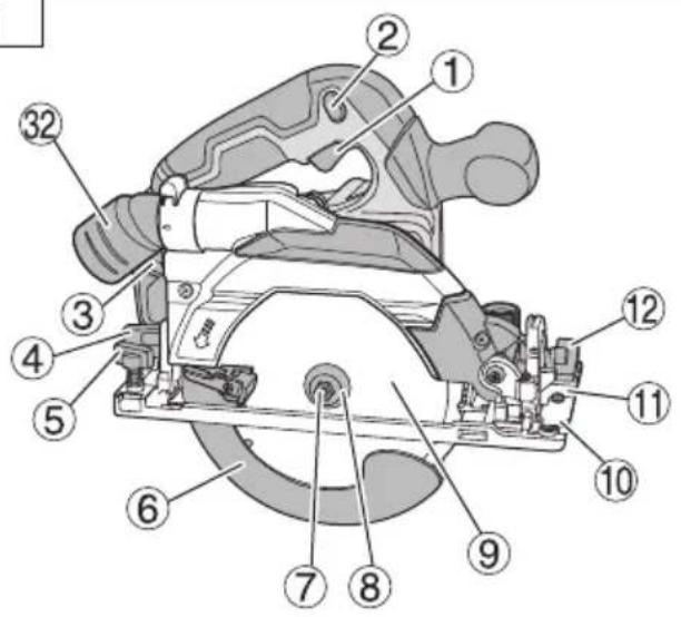
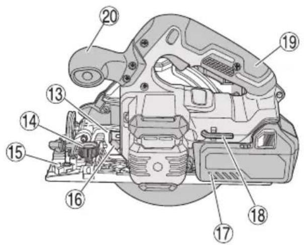
NAMES OF PARTS (Fig. 1–Fig. 33)
| 1 | Switch |
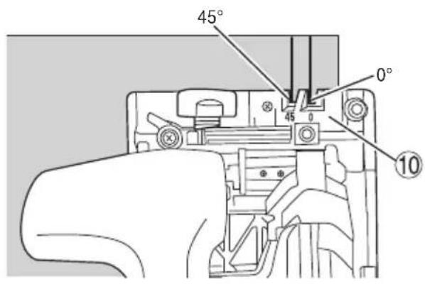
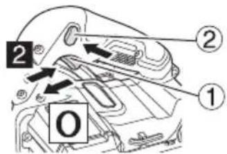
| 2 | Switch lock |
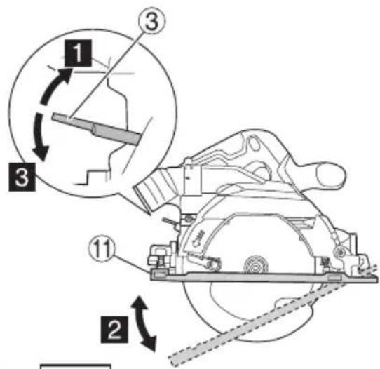
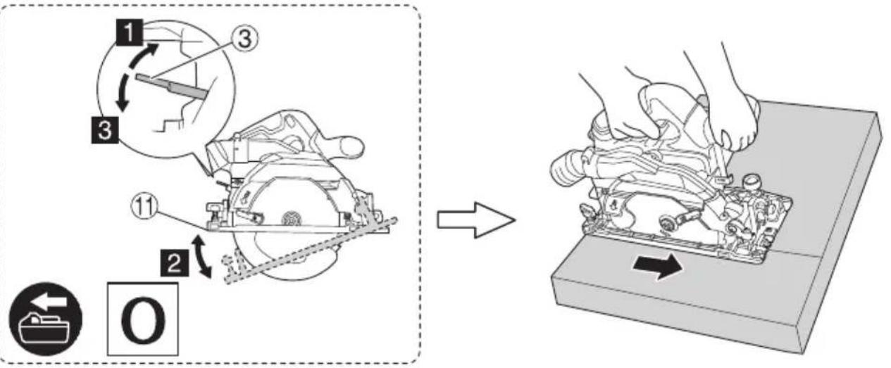
| 3 | Cutting depth lever |
| 4 | Incline wing nut |
| 5 | Guide fastener wing bolt |
| 6 | Lower guard |
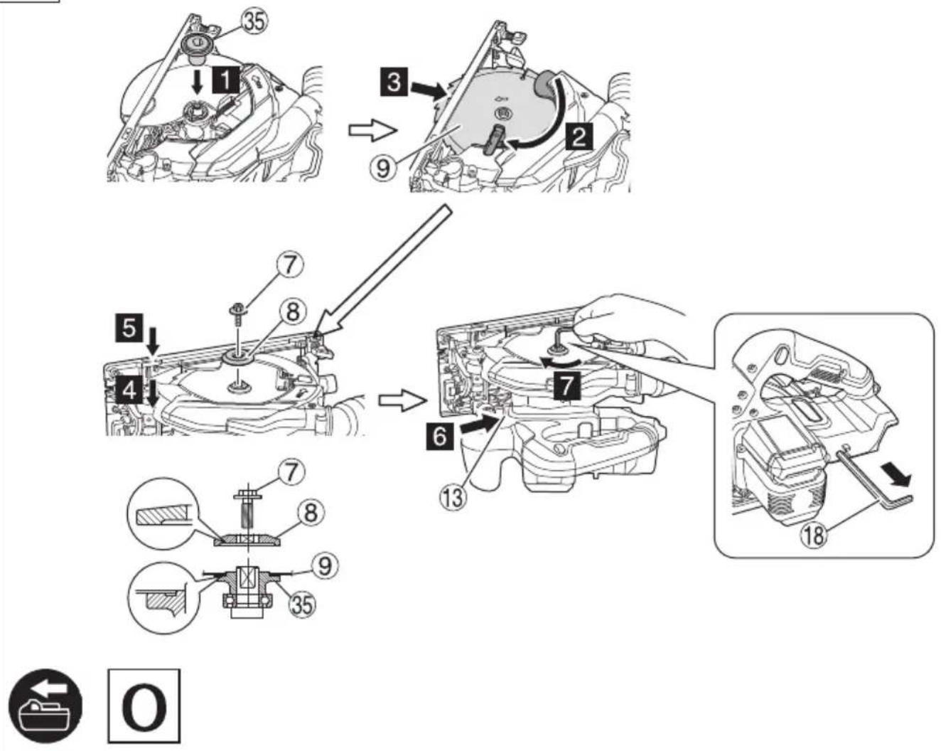
| 7 | Bolt |
| 8 | Washer (B) |
| 9 | Saw blade |
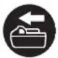
| 10 | Guide piece |
| 11 | Base |
| 12 | Incline wing bolt |
| 13 | Lock lever |
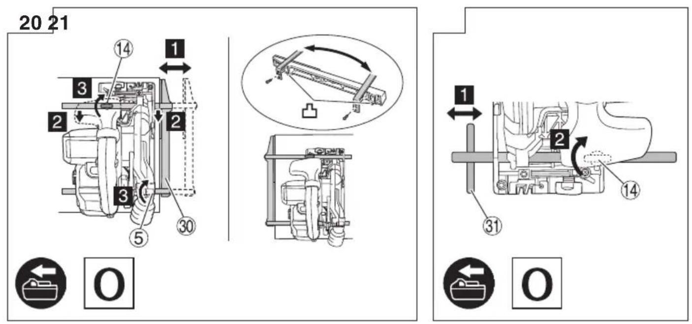
| 14 | Guide fastener knob bolt |
| 15 | Stopper lever |
| 16 | LED light |
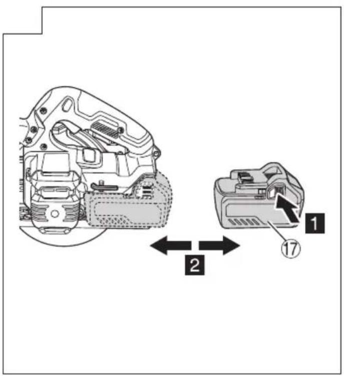
| 17 | Battery |
| 18 | Hex. bar wrench |
| 19 | Handle |
| 20 | Sub handle |
| 21 | M6 fastening screw ( × 2 ) |
| 22 | Parallelism adjustment M6 fastening screw |
| 23 | Bevel piece |
| 24 | Angle adjustment screw |
| 25 | Angle adjustment screw (for 45^ ) |
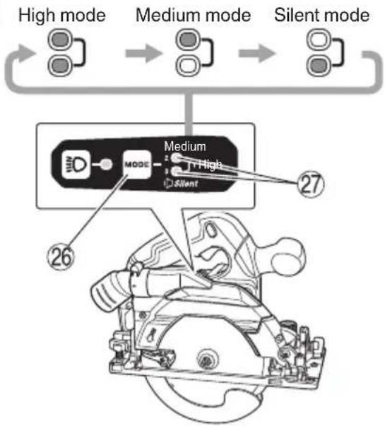
| 26 | Mode selector switch |
| 27 | Silent mode indicator lamp |
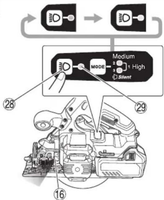
| 28 | Lighting mode switch |
| 29 | Lighting mode indicator lamp |
| 30 | Long guide |
| 31 | Guide |
| 32 | Dust collection nozzle |
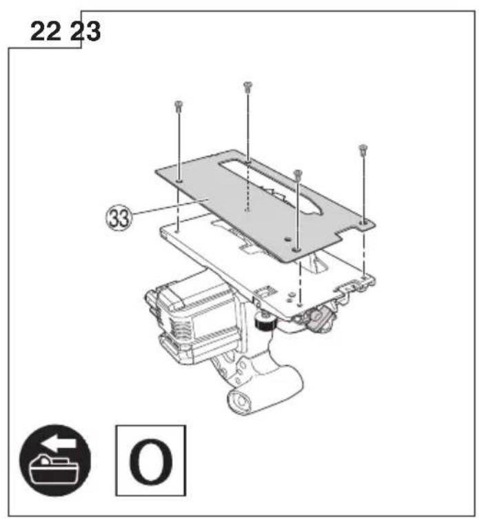
| 33 | Fluorine plate |
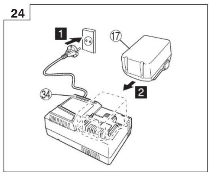
| 34 | Charge indicator lamp |
| 35 | Washer (A) |
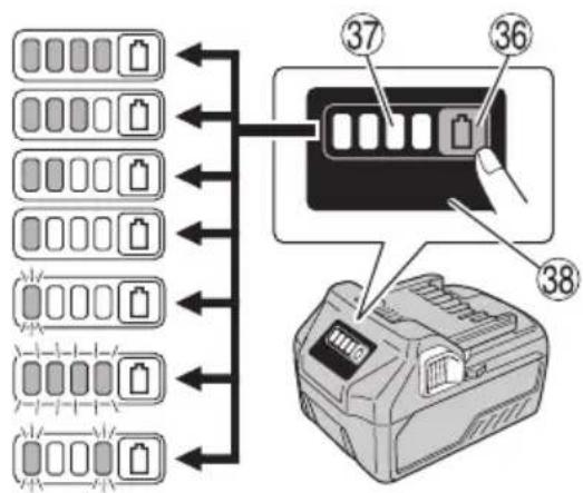
| 36 | Battery level indicator switch |
| 37 | Battery level indicator lamp |
| 38 | Display panel |
SYMBOLS
WARNING
The following show symbols used for the machine. Be sure that you understand their meaning before use.
 | C3606DB: Cordless Circular Saw |
 | To reduce the risk of injury, user must read instruction manual. |
 | Always wear eye protection. |
 | Always wear hearing protection. |
 | Only for EU countriesDo not dispose of electric tools together with household waste material!In observance of European Directive 2012/19/EU on waste electrical and electronic equipment and its implementation in accordance with national law, electric tools that have reached the end of their life must be collected separately and returned to an environmentally compatible recycling facility. |
| V | Rated voltage |
| n_0 | No-load speed |
 | Switching ON |
 | Switching OFF |
 | Disconnect the battery |
 | Warning |
| Prohibited action | |
 | Mode selector switch |
 | Lighting mode switch |
| Always ON (turn off after 60 seconds) | |
 | Always OFF |
 | Remaining battery indicator switch |
Battery
 | Lights;The battery remaining power is over 75% |
 | Lights;The battery remaining power is 50%-75%. |
 | Lights;The battery remaining power is 25%-50%. |
 | Lights;The battery remaining power is less than 25% |
 | Blinks;The battery remaining power is nearly empty.Recharge the battery soonest possible. |
 | Blinks;Output suspended due to high temperature.Remove the battery from the tool and allow it to fully cool down. |
 | Blinks;Output suspended due to failure or malfunction.The problem may be the battery so please contact your dealer. |
NOTE
To prevent the battery power consumption caused by forgetting to turn off the LED light, the light goes off automatically in about 3 seconds.
STANDARD ACCESSORIES
In addition to the main unit (1 unit), the package contains the accessories listed on page 265.
Standard accessories are subject to change without notice.
APPLICATIONS
Cutting various types of wood.
SPECIFICATIONS
- Power tool
| Model C3606DB | |||
| Voltage 36 V | |||
| No-Load Speed | 5600 min-1 (High mode)4300 min-1 (Medium mode)2000 min-1 (Silent mode) | ||
| Capacity | Cutting depth | 90° 66 mm | |
| 45° 45 mm | |||
| -5° 57 mm | |||
| Battery available for this tool* Multi volt battery | |||
| Weight** | 3.4 kg (BSL36A18)3.7 kg (BSL36B18) | ||
* Existing batteries (BSL3660/3620/3626, BSL18 series, etc.) cannot be used with this tool.
** According to EPTA-Procedure 01/2014
NOTE
Due to HiKOKI's continuing program of research and development, the specifications herein are subject to change without prior notice.
English
Electronic control
○ Soft-start
○ Overload protection
This protection feature cuts off the power to the motor in the event of overloading of motor or a conspicuous reduction in rotational speed during operation.
When the overload protection feature has been activated, the motor may stop.
In this case, release the tool switch and eliminate causes of overloading.
After that you can use it again.
○ Overheat protection
This protection feature cuts off the power to the motor and stops the power tool in the event of overheating of motor during operation.
When the overheat protection feature has been activated, the motor may stop.
In this case, release the tool switch and cool it down in a few minutes.
After that you can use it again.
○ Rotation speed changeover function (High mode / Medium mode / Silent mode) (See Fig. 18)
2. Battery
| Model BSL36A18 | |
| Voltage 36 V / 18 V | (Automatic Switching*) |
| Battery capacity | 2.5 Ah / 5.0 Ah(Automatic Switching*) |
| Available cordless products** | Multi volt series, 18 V product |
| Available charger | Sliding charger for lithium ion batteries |
* The tool itself will automatically switch over.
** Please see our general catalogue for details.
CHARGING
Before using the power tool, charge the battery as follows.
1. Connect the charger's power cord to the receptacle.
When connecting the plug of the charger to a receptacle, the charge indicator lamp will blink in red (At 1-second intervals).
- Insert the battery into the charger.
Firmly insert the battery into the charger as shown in Fig. 24 (on page 6).
- Charging
When inserting a battery in the charger, the charge indicator lamp will blink in blue.
When the battery becomes fully recharged, the charge indicator lamp will light up in green. (See Table 1)
(1) Charge indicator lamp indication
The indications of the charge indicator lamp will be as shown in Table 1, according to the condition of the charger or the rechargeable battery.
Table 1
| Charger status | Status of indicator lamp | Indication meaning |
| Before charging | ON/OFF at 0.5 sec. intervals (RED) | Plugged into power source *1 |
| While charging | Lights for 0.5 sec. at intervals of 1 sec. (BLUE) | Charged at less than 50% |
| Lights for 1 sec. at intervals of 0.5 sec. (BLUE) | Charged at less than 80% | |
| Lights continuously (BLUE) | Charged at more than 80% | |
| Charging complete | Lights continuously (GREEN)(Continuous buzzer sound: about 6 sec.) | |
| Overheat standby | ON/OFF at 0.3 sec. intervals (RED) | Battery overheated. Unable to charge. *2 |
| Charging impossible | ON/OFF at 0.1 sec. intervals (PURPLE)(Intermittent buzzer sound: about 2 sec.) | Malfunction in the battery or the charger *3 |
*1 If the red lamp continues to blink even after the charger has been attached, check to confirm that the battery has been fully inserted.
*2 Although charging will start once the battery has cooled down even when left in situ, the best practice is to remove the battery and allow it to cool down in a shaded, well-ventilated location before charging.
*3
○ Fully insert the battery.
○ Check to confirm that no foreign matter is stuck to the battery mount or terminals.
○ Charging will take longer at extremely low ambient temperatures. Charge the battery in a warm location (such as indoors).
- Do not block the air vent. Otherwise the interior will overheat, reducing the charger's performance.
○ If the cooling fan is not operating, contact a HiKOKI Authorized Service Center for repairs.
(2) Regarding the temperatures and charging time of the rechargeable battery
The temperatures and charging time will become as shown in Table 2.
Table 2
| Model UC18YSL3 | ||
| Type of battery Li-ion | ||
| Charging voltage 14.4-18 V | ||
| Temperatures at which the battery can be recharged | 0°C-50°C | |
| Charging time, for battery capacity, approx. (At 20°C) | 1.5 Ah 15 min | |
| 2.0 Ah 20 min | ||
| 2.5 Ah 25 min | ||
| 3.0 Ah | 20 min(BSL1430C, BSL1830C: 30 min) | |
| 4.0 Ah | 26 min(BSL1840M: 40 min) | |
| 5.0 Ah 32 min | ||
| 6.0 Ah 38 min | ||
| 8.0 Ah 52 min | ||
| Multi volt battery | 1.5 Ah(×2 unit) | 20 min |
| 2.5 Ah(×2 unit) | 32 min | |
| 4.0 Ah(×2 unit) | 52 min | |
| Number of battery cells 4-10 | ||
| Charging voltage for USB 5 V | ||
| Charging current for USB 2 A | ||
| Weight 0.6 kg | ||
NOTE
The recharging time may vary according to the ambient temperature and power source voltage.
-
Disconnect the charger's power cord from the receptacle.
-
Hold the charger firmly and pull out the battery. NOTE
Be sure to pull out the battery from the charger after use, and then keep it.
Regarding electric discharge in case of new batteries, etc.
As the internal chemical substance of new batteries and batteries that have not been used for an extended period is not activated, the electric discharge might be low when using them the first and second time. This is a temporary phenomenon, and normal time required for recharging will be restored by recharging the batteries 2–3 times.
How to make the batteries perform longer.
(1) Recharge the batteries before they become completely exhausted.
When you feel that the power of the tool becomes weaker, stop using the tool and recharge its battery. If you continue to use the tool and exhaust the electric current, the battery may be damaged and its life will become shorter.
(2) Avoid recharging at high temperatures.
A rechargeable battery will be hot immediately after use. If such a battery is recharged immediately after use, its internal chemical substance will deteriorate, and the battery life will be shortened. Leave the battery and recharge it after it has cooled for a while.
CAUTION
○ If the battery is charged while it is heated because it has been left for a long time in a location subject to direct sunlight or because the battery has just been used, the charge indicator lamp of the charger lights for 0.3 seconds, does not light for 0.3 seconds (off for 0.3 seconds). In such a case, first let the battery cool, then start charging.
When the charge indicator lamp flickers (at 0.2-second intervals), check for and take out any foreign objects in the charger's battery connector. If there are no foreign objects, it is probable that the battery or charger is malfunctioning. Take it to your authorized Service Center.
MOUNTING AND OPERATION
| Action | Figure | Page |
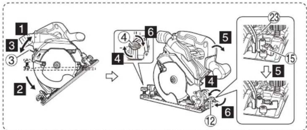
| Inclined cutting using the guide (+45° direction) | 9 | 3 |
| Inclined cutting using the guide (-5° direction) | 10 | 3 |
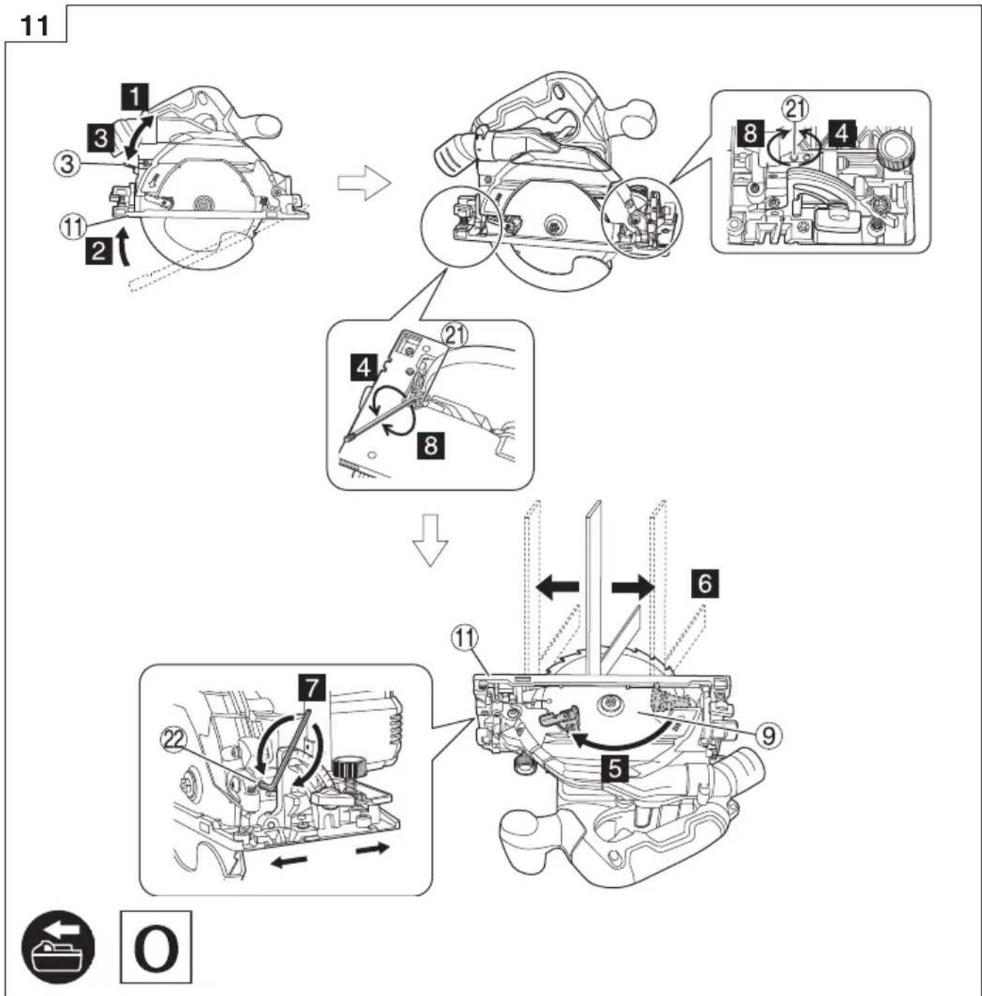
| Fine tuning of parallelism of base sides and saw blade | 11 | 3 |
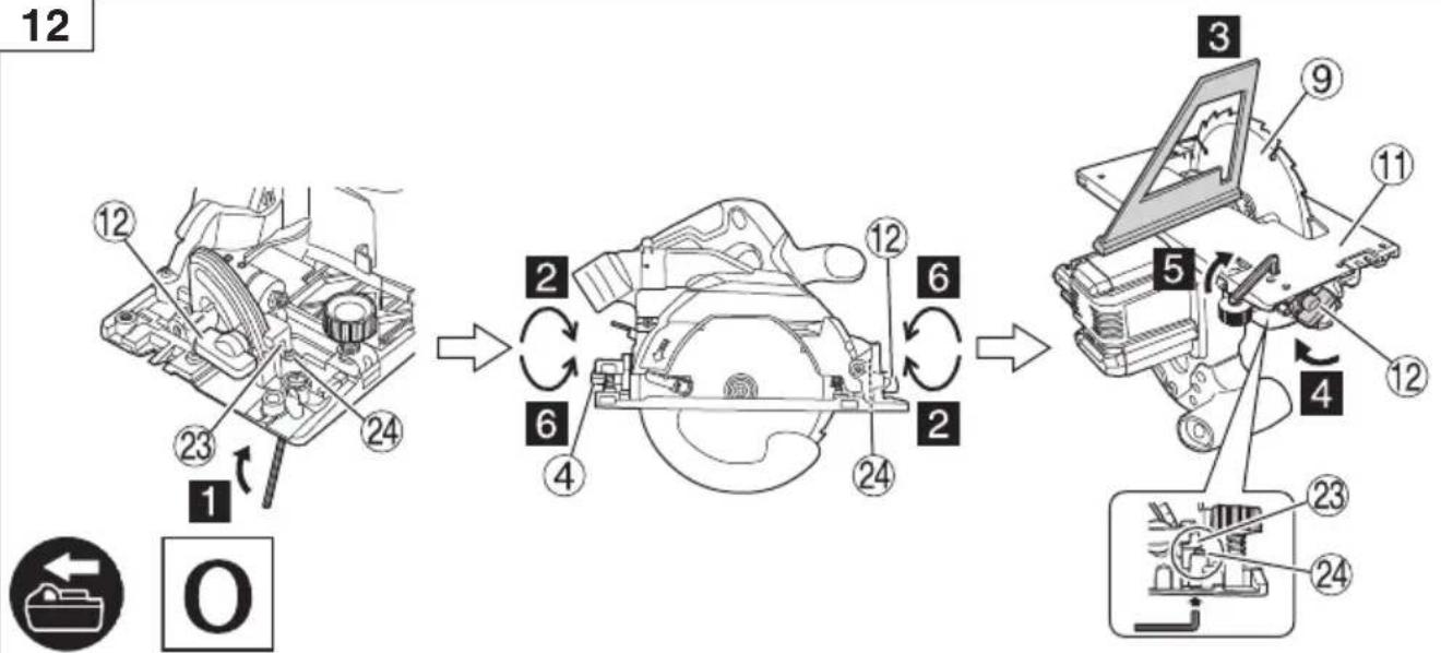
| Fine tuning of inclination angle (When 90°) | 12 | 4 |
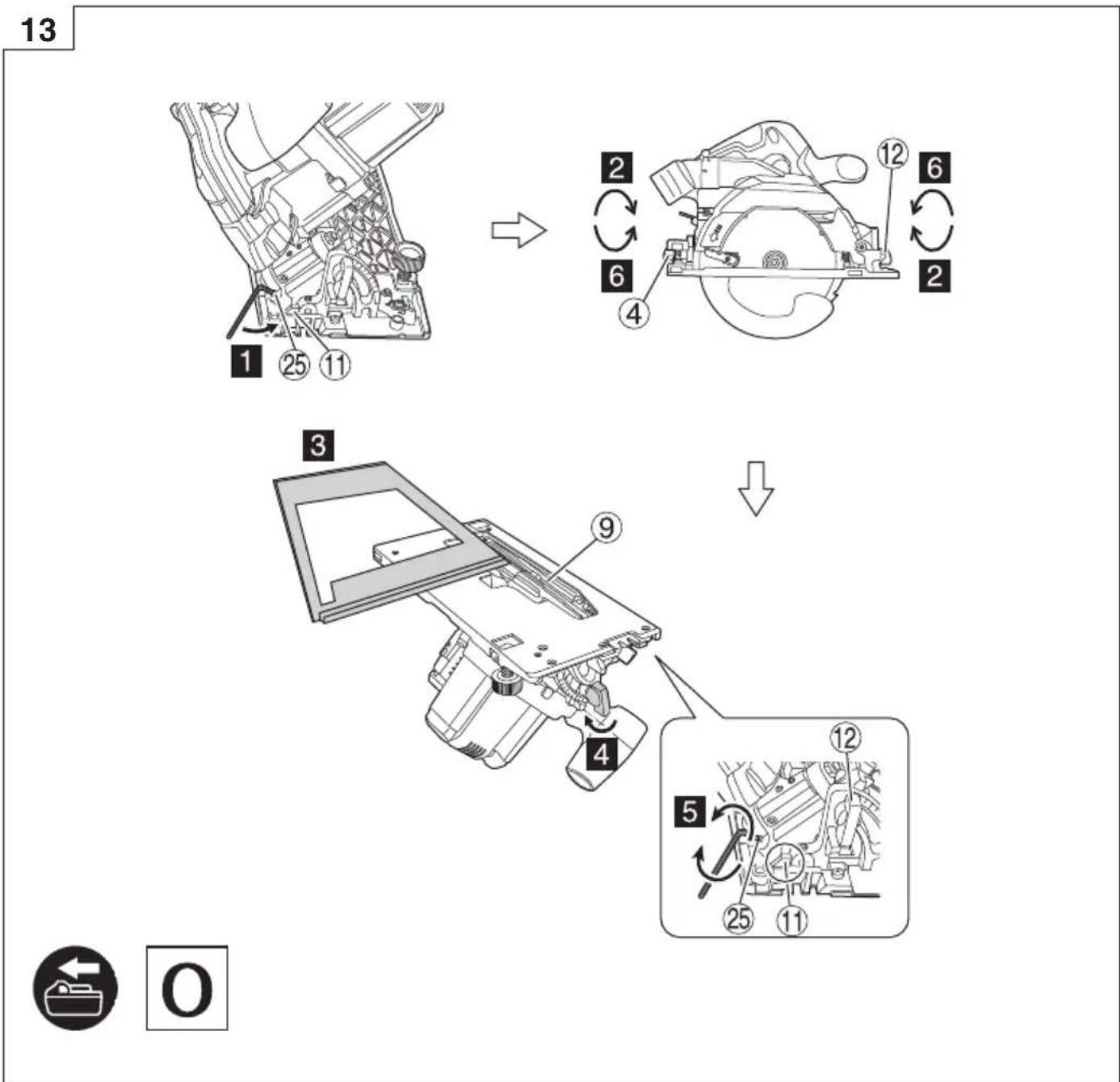
| Fine tuning of inclination angle (When 45°) | 13 | 4 |
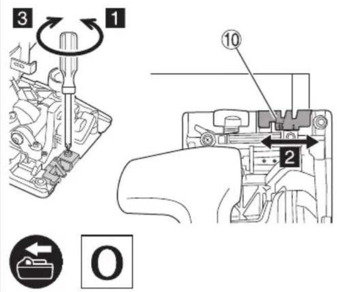
| Fine tuning of guide piece position | 14 | 5 |
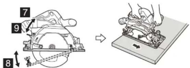
| Adjusting the cutting depth | 15 | 5 |
| Cutting line | 16 | 5 |
| Switch operation | 17 | 5 |
| About the mode select function (*1) | 18 | 5 |
| Using the LED light | 19 | 5 |
| Attaching the long guide (sold separately) | 20 | 6 |
| Attaching the guide | 21 | 6 |
| Attaching the fl uorine plate (sold separately) | 22 | 6 |
| Removing and inserting the battery | 23 | 6 |
| Charging | 24 | 6 |
| Cutting at right angles 25 7 | ||
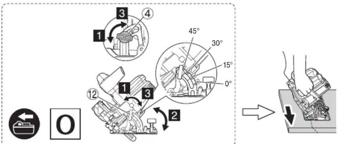
| Inclined cutting (+45° direction) | 26 | 7 |
| Inclined cutting (-5° direction) | 27 | 7 |
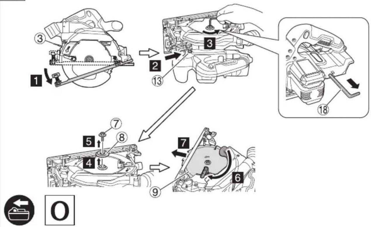
| Dismounting the saw blade | 28 | 8 |
| Mounting the saw blade | 29 | 8 |
| Remaining battery indicator | 30 | 9 |
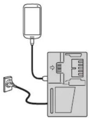
| Charging a USB device from a electrical outlet | 31-a | 9 |
| Charging a USB device and battery from a electrical outlet | 31-b | 9 |
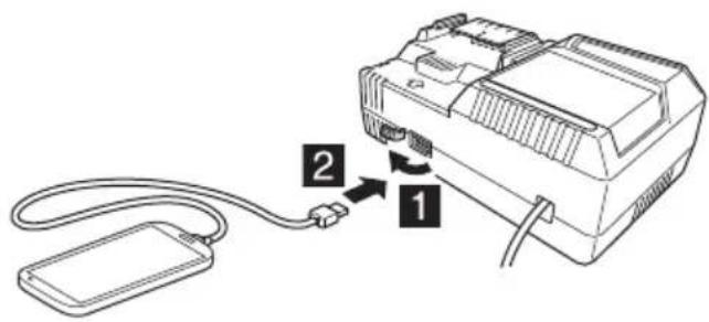
| How to recharge USB device | 32 | 9 |
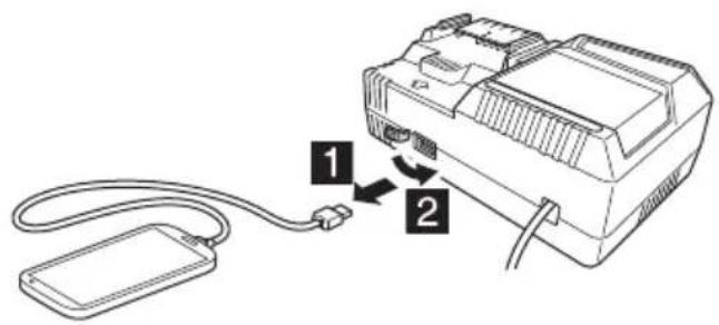
| When charging of USB device is completed | 33 | 9 |
| Selecting accessories | — | 266 |
English
(*1) About the mode select function
Each time the mode selector switch is pushed, the operation mode changes.
Silent mode reduces maximum motor RPM enabling efficient work with less noise.
| Mode No-load speed | |
| High 5600 min | -1 |
| Medium 4300 min | -1 |
| Silent 2000 min | -1 |
NOTE
○ The mode will only change after a battery is installed and the switch lock is pressed once.
☐ The current mode will be maintained even if the switch is on/off, or the battery is removed/reinserted.
LED LIGHT WARNING SIGNALS
This product features functions that are designed to protect the tool itself as well as the battery. While the switch is pulled, if any of the safeguard functions are triggered during operation, the LED light will blink as described in Table 3. When any of the safeguard functions are triggered, immediately remove your finger from the switch and follow the instructions described under corrective action.
Table 3
| Safeguard Function | LED Light Display | Corrective Action |
| Overburden Protection | On 0.1 second/off 0.1 second | Remove the cause of the overloading. |
| Temperature Protection | On 0.5 second/off 0.5 second | Allow the tool and battery to thoroughly cool. |
MAINTENANCE AND INSPECTION
WARNING
Be sure to turned off the switch and remove the battery before maintenance and inspection.
1. Inspecting the saw blade
Since use of as dull saw blade will degrade efficiency and cause possible motor malfunction, sharpen or replace the saw blade as soon as abrasion is noted.
2. Inspecting the mounting screws
Regularly inspect all mounting screws and ensure that they are properly tightened. Should any of the screws be loose, retighten them immediately. Failure to do so could result in serious hazard.
3. Motor unit maintenance
The motor winding is an important part of this tool. Avoid damaging and be careful to avoid contact with cleaning oil or water.
After 50 hours of use, clean the motor by blowing into the ventilation holes of the motor housing with dry air from an air gun or other tool (Fig. 34).
Dust or particle accumulation in the motor can result in damage.
4. Inspecting and maintaining the lower guard
Always make sure that the lower guard moves smoothly. In the event of any malfunction, immediately repair the lower guard.
For cleaning and maintenance, use an air gun or other tool to blow clean the space between the lower guard and gear cover as well as the rotation part of the lower guard with dry air (Fig. 34).
Doing so is effective for the emission of chips or other particles.
Accumulation of chips or other particles around the lower guard may result in malfunction or damage.
WARNING
To prevent dust inhalation or eye irritation, wear protective safety goggles and a dust mask when using an air gun or other tool to clean the lower guard, ventilation holes or other parts of the product.
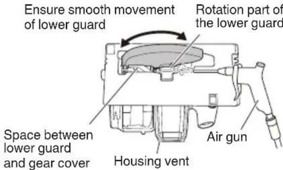
Fig. 34
5. Cleaning the inside of the saw cover
Regularly check and clean to make sure that sawdust and other residue do not collect inside of the saw cover. Always remove the saw blade when checking and cleaning. (Fig. 35)
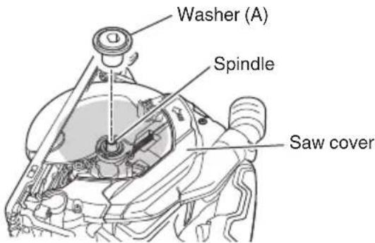
Fig. 35
6. Inspection of terminals (tool and battery)
Check to make sure that swarf and dust have not collected on the terminals.
On occasion check prior, during and after operation.
CAUTION
Remove any swarf or dust which may have collected on the terminals.
Failure to do so may result in malfunction.
7. Cleaning on the outside
When the power tool is stained, wipe with a soft dry cloth or a cloth moistened with soapy water. Do not use chloric solvents, gasoline or paint thinner, for they melt plastics.
8. Storage
Store the power tool and battery in a place in which the temperature is less than 40^ C and out of reach of children.
NOTE
Storing lithium-ion batteries.
Make sure the lithium-ion batteries have been fully charged before storing them.
Prolonged storage (3 months or more) of batteries with a low charge may result in performance deterioration, signifi cantly reducing battery usage time or rendering the batteries incapable of holding a charge.
However, signifi cantly reduced battery usage time m be recovered by repeatedly charging and using the batteries two to five times.
If the battery usage time is extremely short despite repeated charging and use, consider the batteries dead and purchase new batteries.
CAUTION
In the operation and maintenance of power tools, the safety regulations and standards prescribed in each country must be observed.
Important notice on the batteries for the HiKOKI cordless power tools
Please always use one of our designated genuine batteries. We cannot guarantee the safety and performance of our cordless power tool when used with batteries other than these designated by us, or when the battery is disassembled and modified (such as disassembly and replacement of cells or other internal parts).
GUARANTEE
We guarantee HiKOKI Power Tools in accordance with statutory/country specific regulation. This guarantee does not cover defects or damage due to misuse, abuse, or normal wear and tear. In case of complaint, please send the Power Tool, undismantled, with the GUARANTEE CERTIFICATE found at the end of this Handling instruction, to a HiKOKI Authorized Service Center.
Information concerning airborne noise and vibration
The measured values were determined according to EN62841 and declared in accordance with ISO 4871.
Measured A-weighted sound power level: 100 dB (A)
Measured A-weighted sound pressure level: 89 dB (A)
Uncertainty K: 3 dB (A).
Wear hearing protection.
Vibration total values (triax vector sum) determined according to EN62841.
Cutting chipboard:
Vibration emission value a_h = 2.0m / s^2
Uncertainty K = 1.5 m/s²
The declared vibration total value and the declared noise emission value have been measured in accordance with a standard test method and may be used for comparing one tool with another.
They may also be used in a preliminary assessment of exposure.
WARNING
☐ The vibration and noise emission during actual use of the power tool can differ from the declared total value depending on the ways in which the tool is used especially what kind of workpiece is processed; and
- Identify safety measures to protect the operator that are based on an estimation of exposure in the actual conditions of use (taking account of all parts of the operating cycle such as the times when the tool is switched off and when it is running idle in addition to the trigger time).
NOTE
Due to HiKOKI's continuing program of research and development, the specifications herein are subject to change without prior notice.
TROUBLESHOOTING
Use the inspections in the table below if the tool does not operate normally. If this does not remedy the problem, consult your dealer or the HiKOKI Authorized Service Center.
| Symptom Possible | cause Remedy | |
| Tool doesn’t run No remaining battery power Charge the battery. | ||
| Batteries isn’t fully installed. Push the battery in until you hear a click. | ||
| Tool suddenly stopped Tool | was overburdened Get rid of the problem causing the overload protection is in operation. | overburden. |
| The battery is overheated. Let the battery cool down. | ||
| Cannot be inclined The incline wing bolt and incline wing nut are not loosened. | Try inclining after loosening the incline wing bolt and incline wing nut. Tighten the loosened parts after making the necessary adjustments. | |
| Cannot reverse incline The cutting depth is set at maximum. Reverse incline after adjusting the cutting depth to a lesser setting. | ||
| The incline wing bolt and incline wing nut are not loosened. | ||
| Parallelism cannot be fine tuned | The M6 fastening screws (×2) are not loosened. (See Fig. 11) | Loosen each of the M6 fastening screws (×2). |
| Doesn’t cut well The saw blade is worn or missing teeth. Replace with a new saw blade. | ||
| The bolt is loose. Firmly tighten the bolt. | ||
| The saw blade is installed backwards. Install the saw blade in the proper direction. | ||
| Switch can’t be pulled | The switch lock is not pushed in enough. | Push the switch lock in all the way. |
| Sawdust discharge is poor | Sawdust has accumulated in the saw cover. | Remove the sawdust inside the saw cover. |
| Battery cannot be installed | Attempting to install a battery other than that specified for the tool. | Please install a multi volt type battery. |
ALLGEMEINE
natural_image
Line drawing of a rectangular electronic device with a gray top and black arrow pointing to it (no text or symbols)PRÉCAUTIONS LORS DE LA CONNEXION DU DISPOSITIF USB (UC18YSL3)
VEILIGHEIDSWAARSCHUWINGEN
WAARSCHUWINGSSIGNALEN LED-LAMPJE
SIKKERHETSFORHOLDSREGLER FOR ELEKTROVERKT∅Y
ADVARSEL
○ Overopphetingsvern
VEDLIKEHOLD OG INSPEKSJON
ADVARSEL
natural_image
Line drawing of a rectangular electronic device with a central screen and two side connectors (no text or symbols)ПРЕДПАЗНИ МЕРКИ ЗА СВЪРЗВАНЕ НА USB УСТРОЙСТВО (UC18YSL3)
natural_image
Line drawing of a rectangular electronic device with a central screen and two side handles (no text or symbols)MERE PREDOSTROŽNOSTI USB UREĐAJA (UC18YSL3)
Kada se neočekivani problem pojavi, podaci na USB uređaju koji je povezan sa ovim proizvodom mogu da se oštete ili izgube. Uvek se postarajte da sačuvate bilo koje podatke koje USB uređaj sadrži pre nego što počnete da ga koristite sa ovim proizvodom.
Molimo vas da budete svesni da naša kompanija ne prihvata nikakvu odgovornost za bilo koje sačuvane podatke na USB uređaju koji je oštećen ili izgubljen, niti za bilo kakvo oštećenje koje može da se pojavi sa povezanim uređajem.
UPOZORENJE
○ Pre upotrebe, proverite da li spojni USB kabl ima nedostatke ili oštećenje.
Koriščenje neispravnog ili oštećenog kabla USB uređaja može prouzrokovati dim ili paljenje.
Siemensring 34, 47877 willich, Germany
Tel: +49 2154 49930
Fax: +49 2154 499350
URL: http://www.hikoki-powertools.de
Hikoki Power Tools Netherlands B.V.
Brabanthaven 11, 3433 PJ Nieuwegein, The Netherlands
Tel: +31 30 6084040
Fax: +31 30 6067266
URL: http://www.hikoki-powertools.nl
Hikoki Power Tools (U.K.) Ltd.
25 Majestic Road, Southampton, SO16 OYT,
United Kingdom
Tel: +44 1908 660663
Fax: +44 1908 606642
URL: http://www.hikoki-powertools.uk
Hikoki Power Tools France S.A.S.
Hikoki Power Tools Belgium N.V./S.A.
Koningin Astridlaan 51, B-1780 Wemmel, Belgium
Tel: +32 2 460 1720
Fax: +32 2 460 2542
URL http://www.hikoki-powertools.be
Hikoki Power Tools Italia S.p.A
Via Piave 35, 36077, Altavilla Vicentina (VI), Italy
Tel: +39 0444 548111
Fax: +39 0444 548110
URL: http://www.hikoki-powertools.it
Hikoki Power Tools Ibérica, S.A.
C/ Puigbarral, 26-28, Pol. Ind. Can Petit, 08227 Terrassa
(Barcelona), Spain
Tel: +34 93 735 6722
Fax: +34 93 735 7442
URL: http://www.hikoki-powertools.es
Kjeller Vest 7, N-2007 Kjeller, Norway
Tel: (+47) 6692 6600
Fax: (+47) 6692 6650
URL: http://www.hikoki-powertools.no
Hikoki Power Tools Sweden AB
Rotebergsvagen 2B SE-192 78 Sollentuna, Sweden
Tel: (+46) 8 598 999 00
Fax: (+46) 8 598 999 40
URL: http://www.hikoki-powertools.se
Hikoki Power Tools Denmark A/S
Lillebaeltsvej 90, 6715 Esbjerg N, Denmark
Tel: (+45) 75 14 32 00
Fax: (+45) 75 14 36 66
URL: http://www.hikoki-powertools.dk
Hikoki Power Tools Finland Oy
Tupalankatu 9, 15680 Lahti, Finland
Tel: (+358) 20 7431 530
Fax: (+358) 20 7431 531
URL: http://www.hikoki-powertools.fi
Hikoki Power Tools Hungary Kft.
Hikoki Power Tools Romania S.R.L.
Ring Road, No. 66, Mustang Traco Warehouses, Warehouse
No.1, Pantelimon City, 077145, Ilfov County, Romania
natural_image
Line drawing of a quill pen with inkwell, no text or symbols present
natural_image
Line drawing of a quill pen with inkwell, no text or symbols present
natural_image
Line drawing of a quill pen with inkwell, no text or symbols present| English Nederlands | ||
| EC DECLARATION OF CONFORMITYWe declare under our sole responsibility that Cordless Circular Saw, identified by type and specific identification code *1), is in conformity with all relevant requirements of the directives *2) and standards *3). Technical fi le at *4) – See below.The European Standard Manager at the representative office in Europe is authorized to compile the technical fi le.The declaration is applicable to the product affi xed CE marking. | EC VERKLARING VAN CONFORMITEITWij verklaren onder onze eigen verantwoordelijkheid dat Snoerloze cirkelzaagmachine, geïdentificeerd door het type en de specifieke identificatiecode*1), voldoet aan alle relevante bepalingen van de richtlijnen*2) en normen*3). Technische documentatie bij*4) – zie onder.De Europese Normen Manager bij de vertegenwoordiging in Europa is gemachtigd om het technisch dossier samen te stellen.Deze verklaring is van toepassing op producten voorzien van de CE-markeringen. | |
| Deutsch Español | ||
| EG-KONFORMITÄTSERKLÄRUNGWir erklären in alleiniger Verantwortung, dass die durch den Typ und den spezifischen Identifizierungscode *1) identifizierte Akku-Kreissäge allen einschlägigen Bestimmungen der Richtlinien *2) und Normen *3) entspricht. Technische Unterlagen unter *4) – Siehe unten.Die Leitung der repräsentativen Behörde für europäische Normen und Richtlinien ist berechtigt, die technischen Unterlagen zusammenzustellen.Die Erklärung gilt für die an dem Produkt angebrachte CE-Kennzeichnung. | DECLARACIÓN DE CONFORMIDAD DE LA CEDeclaramos bajo nuestra única responsabilidad que la Sierra circular a batería, identificada por tipo y por código de identificación específico *1), está en conformidad con todas las disposiciones correspondientes de las directivas *2) y de las normas *3). Documentación técnica en *4) – Ver a continuación.El Director de Normas Europeas en la oficina de representación en Europa está autorizado para elaborar el expediente técnico.La declaración se aplica al producto con marcas de la CE. | |
| Français Português | ||
| DECLARATION DE CONFORMITE CENous déclarons sous notre entière responsabilité que la scie circulaire sans fil, identifiée par le type et le code d'identification spécifique *1) est en conformité avec toutes les exigences applicables des directives *2) et des normes *3). Dossier technique en *4) - Voir ci-dessous.Le Gestionnaire des normes européennes du bureau de représentation en Europe est autorisé à constituer le dossier technique.Cette déclaration s'applique aux produits désignés CE. | DECLARAÇÃO DE CONFORMIDADE CEDeclaramos, sob nossa única e inteira responsabilidade, que Serra Circular a Bateria, identificada por tipo e código de identificação específico *1), está em conformidade com todos os requerimentos relevantes das diretivas *2) e normas *3). Ficheiro técnico em *4)-Consulte abaixo.O Gestor de Normas Europeas no escritório de representação na Europa está autorizado a compilar o fi cheiro técnico.A declaração aplica-se aos produtos com marca CE. | |
| Italiano Svenska | ||
| DICHIARAZIONE DI CONFORMITÀ CEDichiariamo sotto la nostra esclusiva responsabilità che la sega circolare a batteria, identificata dal tipo e dal codice identificativo specifico *1), è conforme a tutti i requisiti delle direttive *2) e degli standard *3). Documentazione tecnica presso *4) – Vedere sotto.Il gestore delle norme europee presso l'ufficio di rappresentanza in Europa è autorizzato a compilare il fascicolo tecnico.La dichiarazione è applicabile ai prodotti cui sono applicati i marchi CE. | EG-DEKLARATION BETRÄFFANDE LIKFORMIGHETViförklarar på eget ansvar att denna batteridrivna cirkelsåg, identifierad enligt typ och särskild identifikationskod *1), överensstämmer med alla relevanta krav i direktiven *2) och standarderna *3). Teknisk fil enligt *4) – Se nedan.Den europeiska standardansvariga på representationskontoret i Europa är auktoriserad att sammanställa den tekniska fi len.Denna försäkran gäller för produkten med tillhörande CE-märkning. | |
| *1) C3606DB C362888S*2) 2006/42/EC, 2014/30/EU, 2014/35/EU, 2011/65/EU*3) EN62841-1:2015EN62841-2-5:2014EN60335-1:2012+A11:2014EN60335-2-29:2004+A2:2010EN55014-1:2006+A1:2009+A2:2011EN55014-2:1997+A1:2001+A2:2008 | ||
| *4) Representative offi ce in EuropeHikoki Power Tools Deutschland GmbHSiemensring 34, 47877 Willich, GermanyHead offi ce in JapanKoki Holdings Co., Ltd.Shinagawa Intercity Tower A, 15-1, Konan 2-chome, Minato-ku, Tokyo, Japan | 31. 10. 2022Akihisa YahagiEuropean Standard Manager31. 10. 2022 K. YokoyamaGeneral Manager ofQuality Assurance Division K. YokoyamaGeneral Manager ofQuality Assurance Division | |
| Dansk Polski | ||
| EF-OVERENSSTEMMELSESERKLÆRINGVi erklærer os fuldstændige ansvarlige for, at den batteridrevne rundsav, identificeret ved type og specifik identifikationskode *1), er i overensstemmelse med alle relevante krav i direktiverne *2) og standarderne *3). Teknisk fi i *4) – Se nedenfor.Lederen af europæiske standarder på repræsentationskontoret i Europa er bemyndiget til at kompilere den tekniske fi I.Erklæringen gælder produktet, der er mærket med CE. | DEKLARACJA ZGODNOŚCI Z WEOświadczamy na własną wyłączną odpowiedzialność, że Akumulatorowa piła tarczowa podanego typu i oznaczona unikalnym kodem identyfikacyjnym *1) jest zgodna z wszystkimi właściwymi wymogami dyrektyw *2) i norm *3). Dokumentacja techniczna w *4) – Patrz poniżej.Menedżer Norm Europejskich przedstawicielstwa firmy w Europie jest upoważniony do sporządzania dokumentacji technicznej.Niniejsza deklaracja ma zastosowanie do produktu opatzonego znakiem CE. | |
| Norsk Magyar | ||
| EF'S ERKLÆRING OM OVERENSSTEMMELSEVi erklærer på eget ansvar at batteridrevet sirkelsag, identifisert etter type og spesifik identifikasjonskode *1), er i samsvar med alle relevante krav i direktiver *2) og standarder *3). Teknisk fil under *4) - Se nedenfor.Styreren for europeiske standarder ved representantkontoret i Europa er autorisert til å kompilere den tekniske fi len.Erklæringen gjelder for CE-merket på produktet. | EK MEGFELELŐSÉGI NYILATKOZATA kizárólagos felelősségünkre kijelentjük, hogy az Akkus körfűrész, amely típus és egyedi azonosító kód *1) alapján azonosított, megfelel az irányelvek *2) és szabványok *3) vonatkozó követelményeinek. Műszaki fáji a *4) - Lásd alább.AZ EU képviseleti iroda európai szabványügyi menedzsere jogosult a műszaki dokumentáció összeállitására.Jelen nyilatkozat a terméken feltüntetett CE jelzésre vonatkozik. | |
| Suomi Češtiņa | ||
| EY-ILMOITUS YHDENMUKAISUUDESTAVakuutamme yksinomaisella vastuullamme, että akkutoiminen pyőrösaha, joka identifioidaan tyypin ja erityisen tunnistuskoodin *1) perusteella, on kaikkien direktiivien *2) ja standardien *3) asiaankuuluvien vaatimusten mukainen. Tekninen tiedosto kohdassa *4) – katso alta.Eurooppalaisten standardien hallintaelin Euroopan edustustossa on valtuutettu kokoamaan teknisen tiedoston.Ilmoitus on sovellettavissa tuotteeseen kiinnitettyyn CE-merkintään. | PROHLÁŠENÍ O SHODĚ S ESProhlašujeme na svou výhradní zodpovědnost, že akku kotoučová pila, identifikovaná podle typu a specifického identifikačního kódu *1), je v souladu se všemi příslušnými požadavky směrnic *2) a norem *3). Technický soubor *4) - viz niže.K sestavení technické dokumentace je oprávněn manažer pro evropské standardy v evropském obchodním zastoupení.Toto prohlášení plati pro vyrobek označený značkou CE. | |
| Ελληνικά Türkçe | ||
| ΕΚ ΔΗΛΩΣΗ ΕΝΑΡΜΟΝΙΣΜΟΥΔηλώνουμε με αποκλειστική μας ευθύνη ότι το Δισκοπρίονο μιταταρίας, το οποίο προοδιορίζεται από τον τύπο και ειδικό αναγνωριστικό κωδικό *1), είναι σύμφωνο με όλες τις σχετικές απατήσεις των Οδηγιών *2) και με τα σχετικά πρότυπα *3). Τεχνικό Αρχείο στο *4) – Δείτε παρακάτω.Ο Διαχειριστής Ευρωπαϊκών Προτύπων στο γραφείο εκπροσώπησης στην Ευρώπη είναι εξουσιοδοτημένος για τη σύνταξη του τεχνικού φακέλου.Η δήλωση ισχύει μόνο για το προϊόν που είναι τοποθετημένη σήμανση CE. | AT UYGUNLUK BEYANITip ve özel tanım koduyla *1) tanımlı Akülü Daire Testerenin direktiflerinin *2) ve standartların *3) tüm ilgili gereksinimlerine uygun olduğunu tamamen kendi sorumluluğumuz altında beyan ederiz. Teknik dosya *4)'dedir – Aşağıya bakın.Avrupa'daki temsilcilik ofisindeki Avrupa Standartlan Yöneticisi, teknik dosyayi derlemek için yetkilendirilmiştir.Beyan, üzerinde CE işareti bulunan ürünler için geçerlidir. | |
| *1) C3606DB C362888S*2) 2006/42/EC, 2014/30/EU, 2014/35/EU, 2011/65/EU*3) EN62841-1:2015EN62841-2-5:2014EN60335-1:2012+A11:2014EN60335-2-29:2004+A2:2010EN55014-1:2006+A1:2009+A2:2011EN55014-2:1997+A1:2001+A2:2008 | ||
| *4) Representative office in EuropeHikoki Power Tools Deutschland GmbHSiemensring 34, 47877 Willich, GermanyHead office in JapanKoki Holdings Co., Ltd.Shinagawa Intercity Tower A, 15-1, Konan 2-chome,Minato-ku, Tokyo, Japan | 31. 10. 2022Akihisa YahagiEuropean Standard Manager31. 10. 2022 K. YokoyamaGeneral Manager ofQuality Assurance Division K. YokoyamaGeneral Manager ofQuality Assurance Division | |
| Română Български | ||
| DECLARATIE DE CONFORMITATE CEDeclarăm pe propria răspundere că Ferăstrăul circular cu accumulator, identificat după tipul și codul de identificare specific *1), este în conformitate cu toate cerințele relevante ale directivelor *2) și ale standardelor *3). Fișier tehnic la *4) – Vezi mai jos.Managerul standardelor europene de la biroul reprezentanței din Europa este autorizat să întocmească dosarul tehnic.Declarația se referă la produsul pe care este aplicat semnul CE. | EO ДЕНЛАРАЦИЯ ЗА СЪОТВЕТСТВИЕДекларираме на своя собствена отговорност, че Безжичният циркулярен трион, идентифициран по тип и специален идентификационен код *1), е в съответствие с всички съответни изисквания на директивите *2) и стандартите *3). Техническо досие в *4) - Вижте по-долу.Мениджърът по европейските стандарти в представителния офис в Европа е упълномощен да съставя техническото досие.Декларацията е приложима за продукта, който има поставена CE маркировка. | |
| Slovenščina SrpskiES IZJAVA O SKLADNOSTINa lastno odgovornost izjavljamo, da je Akumulatorska krožna žaga, označena z vrsto in posebno identifikacijsko kodo *1), v skladu z vsemi ustreznimi zahtevami direktiv *2) in standardov *3). Tehnična dokumentacija pod *4) – glejte spodaj.Upravitelj evropskih standardov na predstavništvu v Evropi je pooblaščen za pripravo tehnične dokumentacije.Deklaracija je označena na izdelku s pritrjeno oznako CE. | EZ DEKLARACIJA O USAGLAŠENOSTIPod punom odgovornošću izjavljujemo da je Bežična cirkularna testera, identifikovana prema tipu i specifičnom identifikacionom kodu *1), u skladu sa svim relevantnim zahtevima direktiva *2) i standardima *3). Tehnička datoteka pod *4) - Pogledajte dole.Direktor za evropske standarde u kancelariji predstavništva u Evropi je odgovoran za sastavljanje tehničke dokumentacije.Deklaracija je primenjiva na proizvod na koji je stavljena CE oznaka. | |
| Slovenčina HryatskiES VYHLÁSENIE O ZHODETýmto vyhlasujeme na vlastnú zodpovednosť, že výrobok Aku kotúčová pila identifikovaný podľa typu a špecifického identifikačného kódu *1) je v zhode so všetkými príslušnými požiadavkami smerníc *2) a noriem *3). Technický súbor v *4) – Pozrite nižšie.Manažér európsych noriem na zastupujúcom úrade v Európe má oprávnenie na zostavovanie technickej dokumentácie.Toto vyhlásenie sa vzťahuje na výrobok označený značkou CE. | EZ IZJAVA O SUKLADNOSTIIzjavljujemo pod vlastitom odgovornošću da je Bežična cirkularna pila, identificirana prema vrsti i posebnom identifikacijskom kodu *1), u skladu sa svim relevantnim zahtjevima direktiva *2) i standarda *3). Tehnička dokumentacija na *4) - Vidi dolje.Menadžer za europske standarde u europskom predstavništvu tvrtke ovlašten je za sastavljanje tehničke dokumentacije.Izjava se primjenjuje na proizvod na kojem je stavljena CE oznaka. | |
| *1) C3606DB C362888S*2) 2006/42/EC, 2014/30/EU, 2014/35/EU, 2011/65/EU*3) EN62841-1:2015EN62841-2-5:2014EN60335-1:2012+A11:2014EN60335-2-29:2004+A2:2010EN55014-1:2006+A1:2009+A2:2011EN55014-2:1997+A1:2001+A2:2008 | ||
| *4) Representative offi ce in EuropeHikoki Power Tools Deutschland GmbHSiemensring 34, 47877 Willich, GermanyHead offi ce in JapanKoki Holdings Co., Ltd.Shinagawa Intercity Tower A, 15-1, Konan 2-chome,Minato-ku, Tokyo, Japan | 31. 10. 2022Akihisa YahagiEuropean Standard Manager31. 10. 2022  K. YokoyamaGeneral Manager ofQuality Assurance Division K. YokoyamaGeneral Manager ofQuality Assurance Division | |
| DECLARATION OF CONFORMITYWe declare under our sole responsibility that Cordless Circular Saw, identified by type and specific identification code *1), is in conformity with all relevant requirements of the UK regulations *2) and Designated standards *3). Technical file at *4) – See below.This declaration is applicable to the product affixed UKCA marking. | |
| *1) C3606DB C362888S*2) S.I. 2008/1597, 2016/1091, S.I. 2016/1101, S.I. 2012/3032*3) EN62841-1:2015EN62841-2-5:2014EN60335-1:2012+A11:2014EN60335-2-29:2004+A2:2010EN55014-1:2006+A1:2009+A2:2011EN55014-2:1997+A1:2001+A2:2008 | |
*4) Importer and authorized person to compile the technical fi leHikoki Power Tools (U.K.) Ltd.25 Majestic Road, Southampton, SO16 OYT,United Kingdom  Head offi ce in Japan Head offi ce in Japan  Koki Holdings Co., Ltd.Shinagawa Intercity Tower A, 15-1, Konan 2-chome,Minato-ku, Tokyo, Japan Koki Holdings Co., Ltd.Shinagawa Intercity Tower A, 15-1, Konan 2-chome,Minato-ku, Tokyo, Japan | 31. 10. 2022K. YokoyamaGeneral Manager ofQuality Assurance Division |
- GENERAL POWER TOOL SAFETY WARNINGS
- WARNING
- 1) Work area safety
- 2) Electrical safety
- 3) Personal safety
- 4) Power tool use and care
- 5) Battery tool use and care
- 6) Service
- PRECAUTION
- CORDLESS CIRCULAR SAW SAFETY WARNINGS
- Cutting procedures
- Kickback causes and related warnings
- English
- Lower guard function
- ADDITIONAL SAFETY WARNINGS
- CAUTION ON LITHIUM-ION BATTERY
- CAUTION
- REGARDING LITHIUM-ION BATTERY TRANSPORTATION
- USB DEVICE CONNECTION PRECAUTIONS (UC18YSL3)
- NOTE
- SYMBOLS
- STANDARD ACCESSORIES
- APPLICATIONS
- SPECIFICATIONS
- Electronic control
- Battery
- CHARGING
- Connect the charger's power cord to the receptacle.
- Regarding electric discharge in case of new batteries, etc.
- How to make the batteries perform longer.
- LED LIGHT WARNING SIGNALS
- MAINTENANCE AND INSPECTION
- Inspecting the saw blade
- Inspecting the mounting screws
- Motor unit maintenance
- Inspecting and maintaining the lower guard
- Cleaning the inside of the saw cover
- Inspection of terminals (tool and battery)
- Cleaning on the outside
- Storage
- Important notice on the batteries for the HiKOKI cordless power tools
- GUARANTEE
- Information concerning airborne noise and vibration
- TROUBLESHOOTING
- ALLGEMEINE
- PRÉCAUTIONS LORS DE LA CONNEXION DU DISPOSITIF USB (UC18YSL3)
- VEILIGHEIDSWAARSCHUWINGEN
- WAARSCHUWINGSSIGNALEN LED-LAMPJE
- SIKKERHETSFORHOLDSREGLER FOR ELEKTROVERKT∅Y
- ADVARSEL
- VEDLIKEHOLD OG INSPEKSJON
- ПРЕДПАЗНИ МЕРКИ ЗА СВЪРЗВАНЕ НА USB УСТРОЙСТВО (UC18YSL3)
- MERE PREDOSTROŽNOSTI USB UREĐAJA (UC18YSL3)
- UPOZORENJE
- Hikoki Power Tools Netherlands B.V.
- Hikoki Power Tools (U.K.) Ltd.
- Hikoki Power Tools France S.A.S.
- Hikoki Power Tools Belgium N.V./S.A.
- Hikoki Power Tools Italia S.p.A
- Hikoki Power Tools Ibérica, S.A.
- Hikoki Power Tools Sweden AB
- Hikoki Power Tools Denmark A/S
- Hikoki Power Tools Finland Oy
- Hikoki Power Tools Hungary Kft.
- Hikoki Power Tools Romania S.R.L.
Brand : HiKOKI
Model : C3606DB
Category : Saw