Eco Pallas - Fan CasaFan - Free user manual and instructions
Find the device manual for free Eco Pallas CasaFan in PDF.

| Brand | CasaFan |
| Model | Eco Pallas 116 / 142 |
| Product type | Ceiling fan |
| Dimensions (diameter × height) | 1160 × 286 mm (model 116) / 1420 × 286 mm (model 142) |
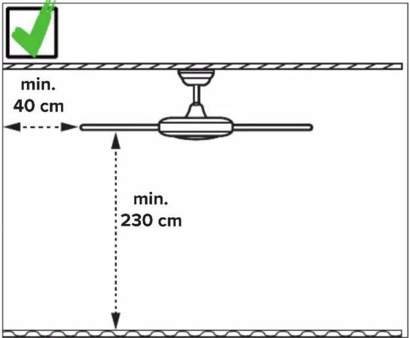
| Ceiling-to-blade distance | Approximately 240 mm |
| Weight | 6.0 kg (model 116) / 6.2 kg (model 142) |
| Rated voltage | 100-240 V ~ |
| Frequency | 50/60 Hz |
| Motor power | 20 W (model 116) / 26 W (model 142) |
| Protection class | I / IP20 |
| Speeds | 6 (remote control) |
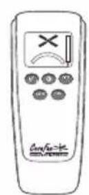
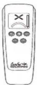
| Remote control | Yes, with 9V battery (type 6F22) |
| Functions | On/off, speed adjustment, timer (1h to 8h), rotation direction reversal, optional lighting |
| Optional lighting | LED PR-LED #3160, #3161 (not included) |
| Built-in protections | Lock protection, overcurrent protection |
| Maintenance and cleaning | Clean with a dry cloth; check all screws once a year |
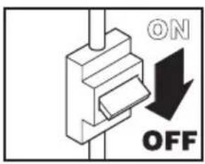
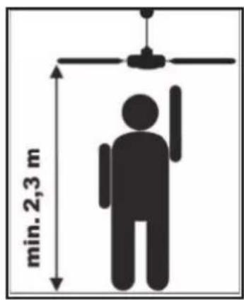
| Safety instructions | Cut power before installation or maintenance; minimum distance to floor: 2.3 m; ceiling mount must support 4 times the weight of the moving fan |
| Spare parts | Balancing set, blades, remote control, screws, ceiling mount |
| Repairability | Repairs exclusively by a qualified electrician |
| Maintenance cycle | Annually (check screws and electrical connections) |
| General information | Compliant with EU Directive 2012/19/EU; do not dispose of with household waste |
Frequently Asked Questions - Eco Pallas CasaFan
User questions about Eco Pallas CasaFan
0 question about this device. Answer the ones you know or ask your own.
Ask a new question about this device
Download the instructions for your Fan in PDF format for free! Find your manual Eco Pallas - CasaFan and take your electronic device back in hand. On this page are published all the documents necessary for the use of your device. Eco Pallas by CasaFan.
USER MANUAL Eco Pallas CasaFan
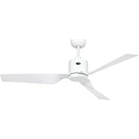
natural_image
Line drawing of a three-bladed cabinet fan with three blades (no text or symbols)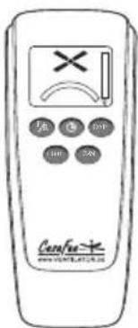
CE UK CA
DECKENVENTILATOR
CEILING FAN
VENTILATEUR DE PLAFOND
VENTILATORE DA SOFFITTO
VENTILADOR DE TECHO
STROPNÍ VENTILÁTOR
PLAFONDVENTILATOR
WENTYLATOR SUFITOWY
Radio frequency: 433,92 MHz
Maximum transmitting power:<10dBm
Eco Pallas
natural_image
Simple line drawing of a person sitting on a bench using a box (no text or symbols)
natural_image
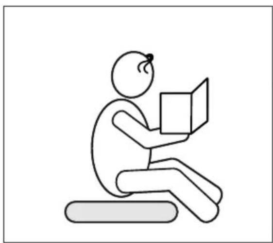
Diagram of a ceiling lamp with a red X mark and wooden panel, no text or symbols present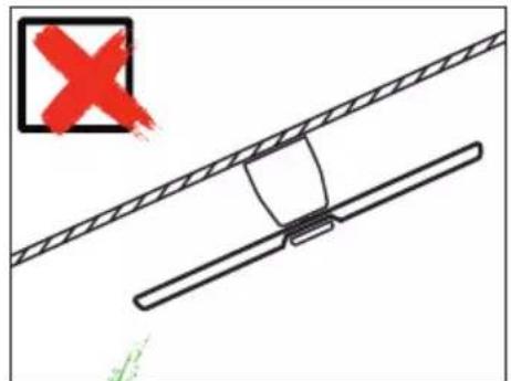
Safety instructions 7–9
Parts 28–29
Assembling....32–43
Installation ceiling bracket 35
Electrical connections ......36
Initial operation 44-47
Coding remote control....46
Operation 48-50
Troubleshooting....52
Cleaning/Maintenance 52
Hints and Tips....59
Disposal....63
IT
INDICE
About this operating manual
Before using the CasaFan fan, read the mounting and operating manual carefully. For the safety of persons it is important to follow these instructions!
| Explanation of symbols: | |
| WARNING: Electric voltage! | ATTENTION: |
| Warns you of immediate danger to life. Indicates risks to health and possible damage to property. | |
| With electrical devices, there is a danger to life from electric shock if used improperly, installed incorrectly or if the safety instructions are not observed! | |
SAFETY ADVICES
- Keep the operating manual within reach. Never pass the fan onto another person without the operating manual.
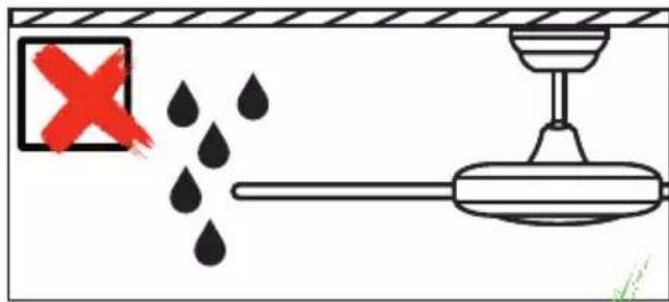
- This ceiling fan is for circulating dry room air. Their use in machines, outside, in garages, in moist or wet rooms or rooms in danger of fire or explosion, is not permitted.
- This appliance can be used by children aged from 8 years and above and persons with reduced physical, sensory or mental capabilities or lack of experience and knowledge if they have been given supervision or instruction concerning use of the appliance in a safe way and understands the hazards involved.
- Cleaning and user maintenance shall not be made by children without supervision.
- If unusual oscillating movement is observed, immediately stop using the ceiling fan and contact the manufacturer, its service agent or suitably qualified persons.
- Replacement of parts of the safety suspension system device shall be performed by the manufacturer, its service agent or suitably qualified persons.
- Mounting of the suspension system shall be performed by the ma-
GB
nufacturer, its service agent or suitably qualified persons:
- Before accessing the connection and installation, the current must be disconnected on all poles (fuse in fuse box).
- Children shall not play with the appliance.
- Ensure that the fan is switched off from the supply mains before service and maintenance.
- The electrical connection and electrical maintenance of this fan may only be carried out by a trained electrician, a skilled electrician or an appropriately qualified person.
- The voltage details on the rating label are to conform with the available mains voltage.
- Only operate the ceiling fan when completely assembled!
- WARNING! The mains connection requires a two-pole isolating switch with a contact opening width of at least 3 mm. The disconnecting device must be integrated into the fixed wiring according to the valid technical regulations.
- The electrical safety of the fan is only guaranteed if the earthing system of the building installation is installed according to regulations and connected to the fan.
- The mains connection to which the fan is connected must comply with the applicable local standards.
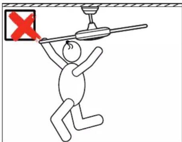
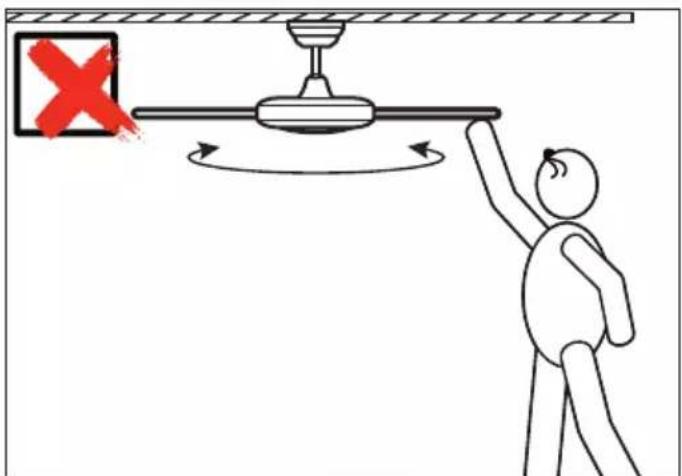
- Choose a safe place for installation and make sure that there are no objects within the area of rotation.
- The construction and fixture of the holder and ceiling is to be able to bear 4 times the weight of the fan when being moved.
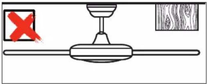
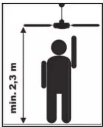
- None of the fan blades are to be less than 2.3 m from the ground.
- Before first using after the setup, all electrical and mechanical connections are to be checked in order to prevent any fall, fire or electric shock.
Observe notes on disposal!
Our ceiling fans are quality products and designed for a long service life.
- Do not dispose of a appliance at the end of its service life and any batteries required to operate the appliance in household waste!
- Find out about local return and recycling possibilities and use the existing collection points in your area for disposal.
- Dispose of packaging material that is no longer required in an environmentally friendly manner and inaccessible to children.
- There is a risk of suffocation for children by inhaling or swallowing parts of the packaging.
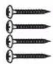
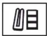
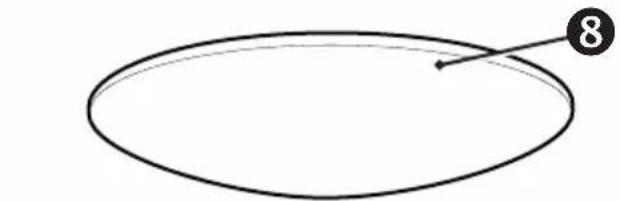
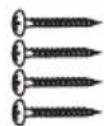
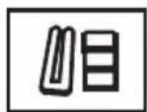
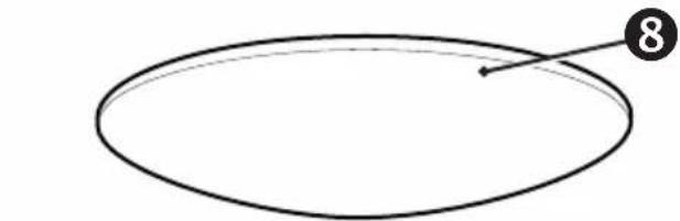
PARTS (Figure A, page 28)
Unpack the fan and compare the package contents for completeness. All the parts shown in the figure are to be present and undamaged.
| Technical data: | ||
| Type Eco Pallas 116 Eco Pallas 142 | ||
| Mains voltage 100 - 240 V | ~ | |
| Frequency 50/60 Hz | ||
| Power motor 20 W (max.) 26 | W (max.) | |
| Protection class I/IP20 | ||
| No. of speeds 6 (with remote control) | ||
| Dimensions ∅ × H (mm) approx. 1160 × 286 approx. 1420 × 286 | ||
| Distance ceiling – blades approx. 240 mm | ||
| Weight approx. 6,0 kg approx. 6,2 kg | ||
| Optional light kit | PR-LED #3160, #3161 | |
| Service interval | once a year | |
| Subject to technical modifications. | ||
10
natural_image
Grid of identical black circular icons arranged in three rows and four columns (no text or symbols)11
12
13
natural_image
Simple line drawing of an oval shape with a numbered point and arrow (no text or symbols)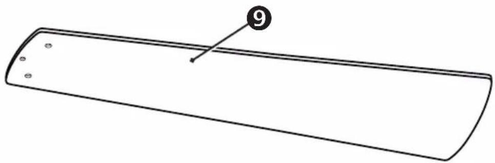
natural_image
Simple line drawing of a rectangular object with a numbered label '9' pointing to its edge (no text or symbols beyond the number)
DE
① Ceiling Bracket
② Canopy Screw (4×)
③ Terminal Block
4 Canopy Ring
5 Safety rope
⑥ Fan wire
⑦ Motor Assembly
8 Lower Cover
⑨ Blade (3×)
10 Remote Control
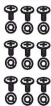
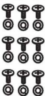
11 Blade Screw/Flat Washer (9×)
12 Screws for wooden ceiling (4×)
13 Balancing kit
FR
10
natural_image
Grid of identical black circular icons with plus and minus signs, no text or symbols present11
12
13
natural_image
Simple oval shape with a numbered arrow pointing to the top-right corner (no text or symbols)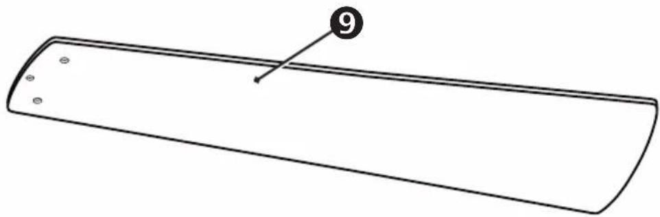
natural_image
Simple line drawing of a rectangular object with a numbered label '9' pointing to its edge (no text or symbols on the object itself)
ES
min. 25 kg !
DE
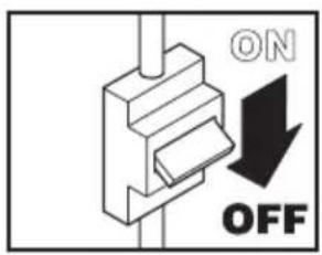
WARNING: Danger of electric shock! Before commencing installation, turn off electricity supply at the main power box or disconnect power by removing fuse.
ATTENTION: Follow all installation directions. Improper installation can lead to injuries and material damage.
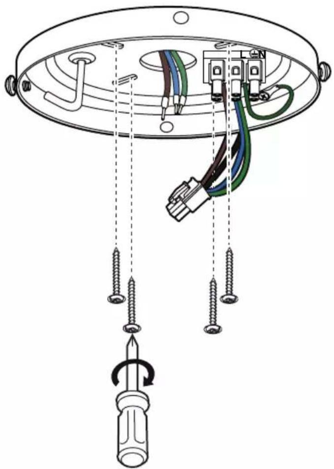
- The place of installation (ceiling) must have a load capacity of at least 25 kg. - Use only for your type of ceiling suitable screws and plugs (not supplied).
FR
natural_image
Diagram of a ceiling lamp with wires and a screwdriver, showing wiring connections without any text or symbols.GB Remove 2 opposing screws from the ceiling bracket and loosen the other 2 screws by about 2 turns.
GB Place the canopy ring on the motor assembly and slide the ring down.
natural_image
Technical line drawing of a mechanical component with a handle and base plate (no text or symbols)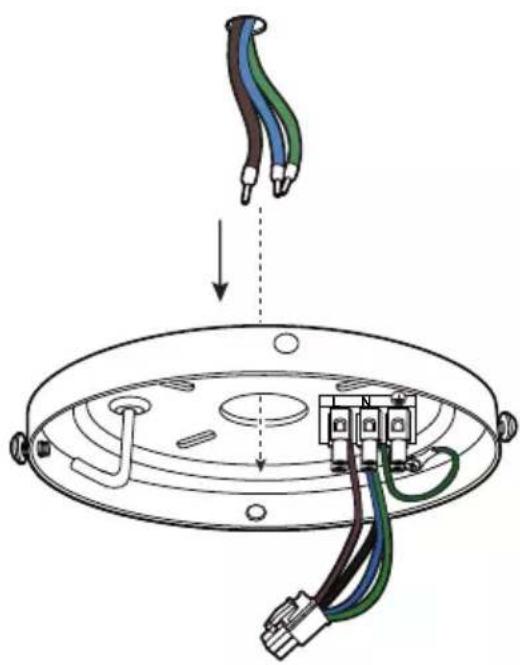
natural_image
Diagram of a ceiling lamp installation showing screwdriver, cable, and connector components (no text or labels)GB Securely attach the hanger bracket to the ceiling joist using the lag bolts supplied. Use only for your type of ceiling suitable screws and bolts (not supplied).
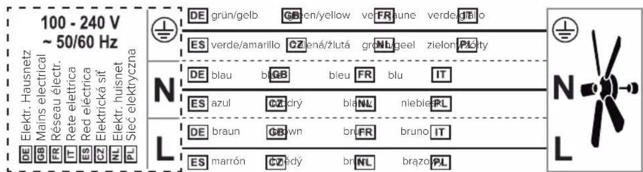
DE Schließen Sie die Kabel mit der Netzspannung an die Lüsterklemme an.
GB Connect the cables with the mains voltage to the luster terminal.
FR Connectez les câbles avec la tension du secteur à la terminal luster.
IT Collegare i cavi con la tensione di rete al terminale luster.
ES Conecte los cables con el voltaje de la red al bloque de terminales.
CZ Připojte zástrčky podle obrázku a připojte síťové napětí k terminálu.
NL Sluit de kabels met de netspanning aan op de aansluitblok.
PL Podłączyć przewody z napięciem sieciowym do blok zacisków.
natural_image
Technical line drawing of a mechanical component with exposed wiring and a top view showing internal structure (no text or symbols)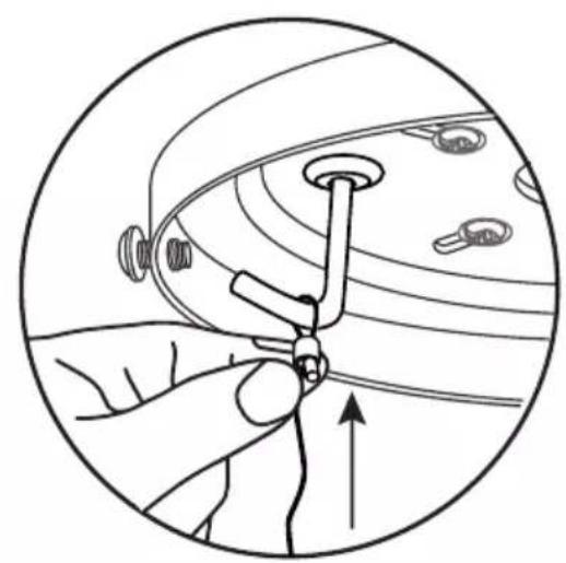
natural_image
Illustration of a hand adjusting a small mechanical component within a circular frame (no text or symbols)
natural_image
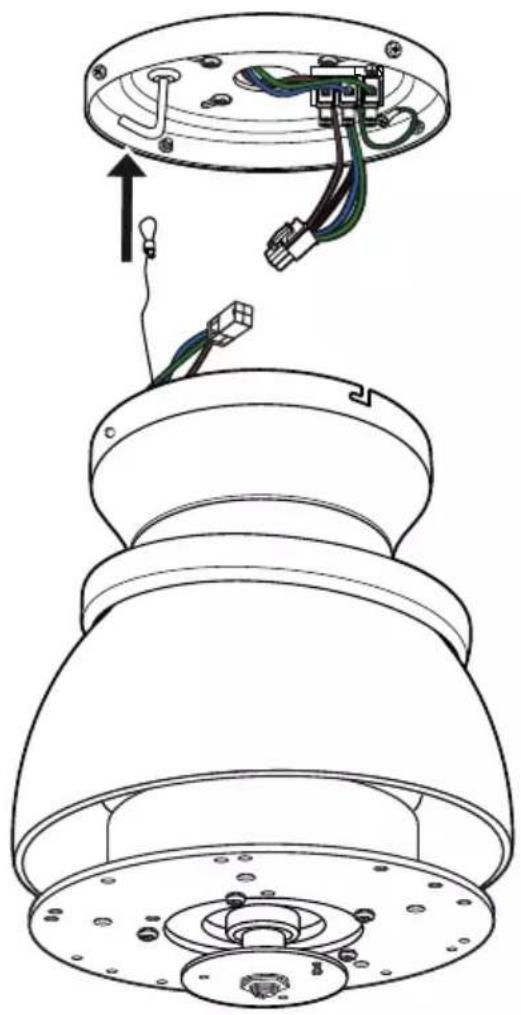
Diagram of a mechanical or electrical component with curved lines and circular elements, no visible text or symbolsGB Guide the safety rope over the hook on the ceiling bracket and tighten it firmly. - The safety rope holds the motor and helps you with the connection work.
natural_image
Diagram showing two connected electrical connectors with colored wires, no text or symbols presentDE Stecken Sie die beiden Stecker zusammen, um den Motor mit Strom zu versorgen.
GB Plug the two connectors together to provide power to the motor.
FR Branchez les deux connecteurs ensemble pour alimenter le moteur.
IT Collegare i due connettori per alimentare il motore.
ES Conecta los dos conectores para alimentar el motor.
CZ Pro napájení motoru připojte oba konektory.
NL Verbind de twee connectors met elkaar om de motor van stroom te voorzien.
PL Podłączyć oba złącza do siebie, aby zapewnić zasilanie silnika.

GB Insert the motor unit with the bayonet holder into the two screws on the ceiling bracket. - Turn the motor unit to the right until it engages.
natural_image
Technical line drawing of a mechanical component with a screwdriver inserted, showing internal parts and alignment lines (no text or symbols)GB Insert the 2 previously removed screws again.
- Tighten all 4 screws.
natural_image
Technical line drawing of a device interior with three views showing internal components and directional arrows (no text or symbols)GB Slide the canopy ring onto the screws in the ceiling bracket.
- Turn the canopy ring to the right until the bayonet catches.
natural_image
Technical diagram of a ceiling fan assembly with screwdriver and mechanical components, showing internal components and a close-up inset (no text or symbols)GB Insert the blade into the opening on the motor block and fasten it with the screws and washers provided.
- Tighten the screws, but do not over-tighten them.
natural_image
Technical line drawing of a ceiling fan assembly with no text or symbolsGB Turn the lower cover onto the motor shaft. Do not overtighten, otherwise the cover will be damaged!
Your ceiling fan is now ready for initial operation.
- Several ceiling fans can be connected to a single hand-held transmitter.
- If several fans within radio range are to be programmed on their own hand-held transmitters, only the fan currently to be programmed must be switched on. The same applies to reprogramming and teaching new blade sizes and numbers.
FR NOTE SUR LA TÉLÉCOMMANDE
Insert 1 battery type 6F22 (9V) into the transmitter of remote control. Do not press any button yet!

GB Switch on the electricity supply for the ceiling fan (fuse).
GB Within first 30 seconds after power on: Press the "OFF" button until you hear two BEEP tones until confirmed.
GB Teach-in size and number of blades
GB Within the first 30 seconds after switching on the power and inserting the battery: Press the "FAN" button until you hear 3 BEEP tones.
- The motor will now run from maximum speed to standstill. The highest level is indicated in the display of the remote control.
- At the end of the teach-in procedure, another 3 BEEP tones will sound for confirmation. Your ceiling fan is now ready for operation.
natural_image
Simple diagram showing a windmill icon above an arc and a vertical line with a flame symbol (no text or labels)DE Bedienung
GB Operation
FR Fonctionnement
IT Funzionamento
ES Operación
CZ Obsluha
NL Bediening
PL Obstuga
GB Press the "FAN" button to start the fan on low speed.
natural_image
Simple diagram showing a cross-shaped symbol with an arrow and a curved line below, no text or labels present.GB Pressing the "FAN" button again will switch the fan motor one step faster.
natural_image
Simple diagram showing a wind turbine with a downward arrow and a curved arc, next to a vertical line (no text or symbols)GB Press the "F/R" button to change the direction of rotation.
natural_image
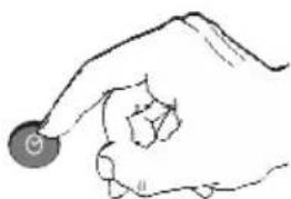
Simple diagram showing a wind turbine above an arc and a vertical line with a flame symbol (no text or labels)GB While the motor is running, press the ⏻ button to set the shutdown timer. When the set time has elapsed, the fan switches off.
GB Each press on this button increases the time of the shutdown timer by one hour.
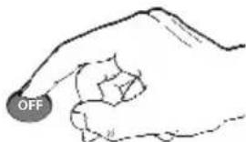
GB Press the "OFF" button to turn off the ceiling fan.
natural_image
Simple line drawing of a hand holding a circular object (no text or symbols)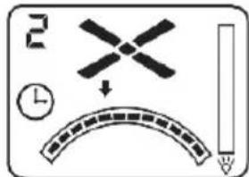
natural_image
Simple line drawing of a hand holding a circular object (no text or symbols)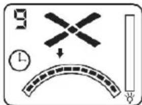
NOTE: The luminaire is optional and is not supplied with your ceiling fan.
natural_image
Hand holding a light bulb (no text or symbols present)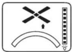
natural_image
Simple diagram with a windmill symbol above an arc and a vertical bar on the right (no text or labels)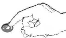
natural_image
Simple diagram with a windmill symbol above an arc and a vertical line, no text or labels present.| GB NOTES FOR REMOVING FAULTS | |
| Fault Remedy | |
| The fan does not start | - Check the fuses/trips at the main box and other connections.- Check the fan connection to the mains.- Repeat coding of the fan with the handheld transmitter.- Replace the battery in the handheld transmitter if necessary. |
| The fan is noisy | - Check that all bolts and screws have been tightened.- Run in the fan and the bearings for 24 hours. Most noises disappear after this time. |
| The fan vibrates too much | - All screws during assembly of the ventilator, especially those relating to the axis, have an important function. Not tightened screws are the main cause of imbalances.Please make sure that all screws are tightened.- All blades have been weighed and grouped according to weight Wood is a natural material. Their density can vary and therefore cause vibration even when all blades are of the same weight. If the blade screws of one of the blades are not tightened properly, this could cause massive wobbeling.NOTE: Movement of up to 10 mm is quite acceptable and does not mean a faulty ceiling fan.- Check that the ceiling bracket is firmly anchored to the ceiling. |
| Important:Opening up and repairing the unit may only be carried out by a qualified electrician! | |
CLEANING/MAINTENANCE

WARNING: Danger of electric shock! Turn off the electricity at the fuse
box or circuit breaker before cleaning or servicing your fan.
- Never use water for cleaning your ceiling fan. The appliance must not get wet.
- Do not use petrol or any similar light flammable detergents!
- Clean the surface of the housing and the blades with a dry cleaning cloth.
Regular check
- Check once a year all the screws, especially those of the ceiling suspension, for tightness, retighten if necessary.
- Check electrical connections for proper connection.
Lock protection: The EC/DC motor has a built-in safety feature against blade or motor obstruction during operation. If something obstructs the fan blades or motor, the motor will keep trying to run and then stop operation after about 30 seconds of interruption. Please remove obstacles and reset.
To reset: Turn the fan off by remote transmitter and then turn the fan on.
Over load protection (current limit): The device will limit the maximum current output from the receiver/drive if the fan load has increased abnormally.
Tips
- If your fan is operates automatically after installation and power on, it is because your fan has memorized the previous factory setting. Use the Universal Mode or the learning function and your fan will be ready for use.
- If the fan or light isn't working, reset power (turn the power off for at least 5 seconds and then turn the power back on) and redo the learn function setting.
- It is not possible to remotely operate more than one fan in the same room (in the area where the remote signal can reach to) if they share the same power supply. Separate power supplies (such as using individual wall switches for each fan) is required if you want to separately control more than one fan in same room.
- When the fan is turned on or operated using forward/reverse function, it shutters & goes back & forth until it turns. This is normal and it will take a few seconds to run this operation.
This product conforms to EU Directive 2012/19/EU. This appliance bears the symbol of the barred waste bin. This indicates that, at the end of its useful life, it must not be disposed of as domestic waste, but must be taken to a collection centre for waste electrical and electronic equipment, or returned to a retailer on purchase of a replacement.
It is the user's responsibility to dispose of this appliance trough the appropriate channels at the end of its useful life. Failure to do so may incur the penalties established by laws governing waste disposal. Proper differential collection, and the subsequent recycling, processing and environmentally compatible disposal of waste equipment avoids unnecessary damage to the environment and possible related health risks, and also promotes recycling of the materials used in the appliance. For further information on waste collection and disposal, contact your local waste disposal service, or the shop from which you purchased the appliance. Manufacturers and importers fulfil their responsibilities for recycling, processing and environmentally compatible disposal either directly or by participating in collective systems.
ATTENTION
CasaFan reserves the right to make any changes to the product without prior notice.