Caribbean Dream Eco II - Fan CasaFan - Free user manual and instructions
Find the device manual for free Caribbean Dream Eco II CasaFan in PDF.

| Product Type | Ceiling Fan |
| Brand | CasaFan |
| Model | Caribbean Dream Eco II |
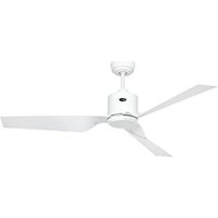
| Dimensions (diameter × height) | ∅1370 × 360 mm (natural palm) / ∅1370 × 355 mm (antique rattan RTN) |
| Ceiling-to-blade distance | 340 mm (natural palm) / 335 mm (antique rattan RTN) |
| Weight | Approximately 6.8 kg (natural palm) / 8.6 kg (antique rattan RTN) |
| Power supply | 100-240 V ~, 50/60 Hz |
| Motor power | 1.1 - 25.6 W |
| Protection class | I / IP20 |
| Number of speeds | 6 speeds (with remote control) |
| Main functions | Timer, reversible rotation direction, optional lighting |
| Remote control | Yes, with 9V battery (type 6F22) |
| Blade material | Natural wood (palm or antique rattan) |
| Maintenance | Clean with a dry cloth; check screws and connections once a year |
| Safety | Safety cord, automatic shut-off in case of blockage, overload protection |
| Installation | Must be carried out by a qualified electrician; requires a bipolar disconnect switch |
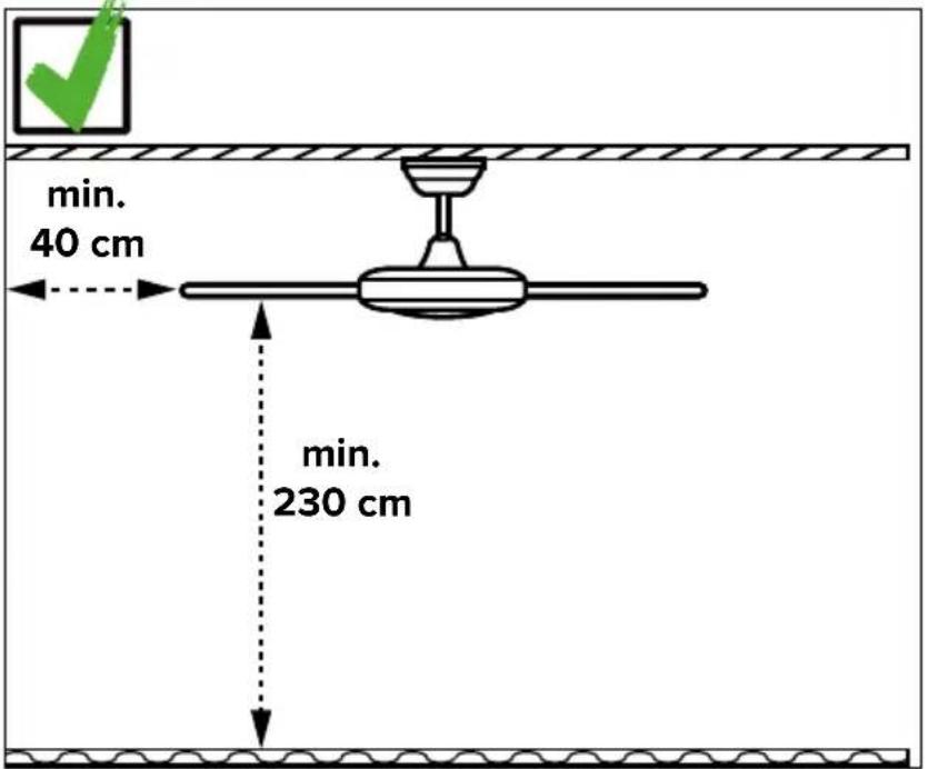
| Minimum mounting height | 2.3 m between blades and floor |
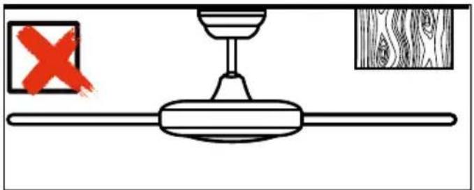
| Minimum distance from heat sources | 1.5 m |
| Spare parts and repairability | Suspension parts can only be replaced by an approved professional with original parts |
| General information | Maintenance cycle: annually; subject to technical changes |
Frequently Asked Questions - Caribbean Dream Eco II CasaFan
User questions about Caribbean Dream Eco II CasaFan
0 question about this device. Answer the ones you know or ask your own.
Ask a new question about this device
Download the instructions for your Fan in PDF format for free! Find your manual Caribbean Dream Eco II - CasaFan and take your electronic device back in hand. On this page are published all the documents necessary for the use of your device. Caribbean Dream Eco II by CasaFan.
USER MANUAL Caribbean Dream Eco II CasaFan
natural_image
Technical line drawing of a four-blade propeller fan assembly (no text or symbols)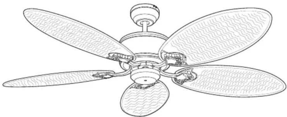
natural_image
Line drawing of a five-blade propeller with mesh blades and central hub (no text or symbols)CARIBBEAN DREAM ECO II
DECKENVENTILATOR CEILING FAN
VENTILATEUR DE PLAFOND
VENTILATORE DA SOFFITTO
VENTILADOR DE TECHO
STROPNÍ VENTILÁTOR
PLAFONDVENTILATOR
WENTYLATOR SUFITOWY
CE
Radio frequency: 433,92 MHz
Maximum transmitting power:<10dBm
natural_image
Simple line drawing of a person sitting on a bench using a book (no text or symbols)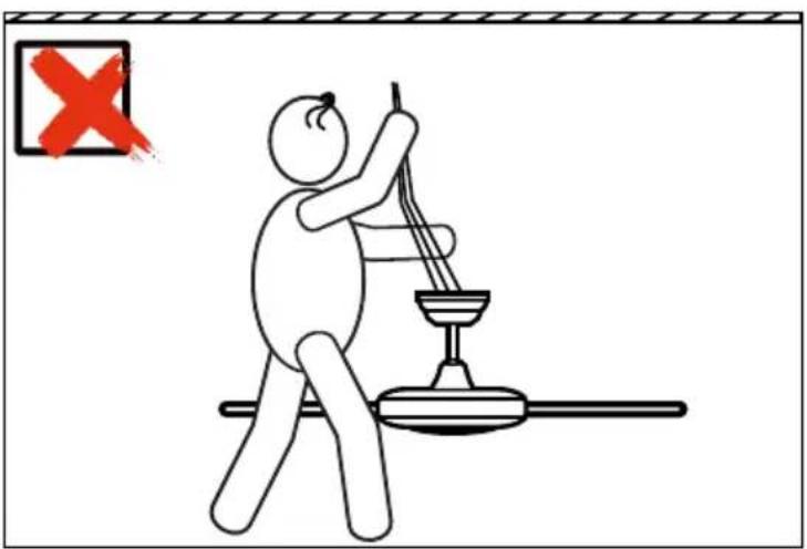
natural_image
Diagram of a ceiling fan with a handle and wooden panel, showing a red X mark and a blue square (no text or symbols)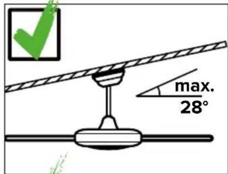
Installation ceiling bracket ....32 - 34
Electrical connections 38
Assembling....35 - 41
Initial operation/Recoding 42 - 45
Operation....45-47
Troubleshooting....49
Cleaning/Maintenance 49
Hints and Tips....56
Disposal....60
IT
INDICE
About this operating manual
Before using the CasaFan fan, read the mounting and operating manual carefully. For the safety of persons it is important to follow these instructions!
| Explanation of symbols: | |
| WARNING: Electric voltage! | ATTENTION: |
| Warns you of immediate danger to life. Indicates risks to health and possible damage to property. | |
| With electrical devices, there is a danger to life from electric shock if used improperly, installed incorrectly or if the safety instructions are not observed! | |
SAFETY ADVICES
- Keep the operating manual within reach. Never pass the fan onto another person without the operating manual.
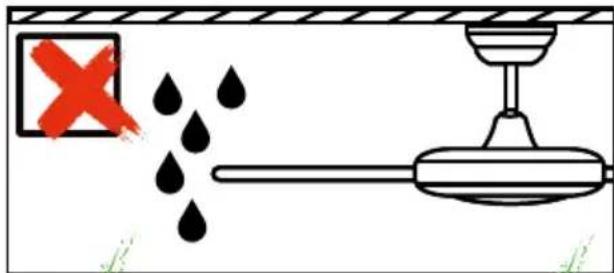
- This ceiling fan is for circulating dry room air. Their use in machines, outside, in garages, in moist or wet rooms or rooms in danger of fire or explosion, is not permitted.
- This appliance can be used by children aged from 8 years and above and persons with reduced physical, sensory or mental capabilities or lack of experience and knowledge if they have been given supervision or instruction concerning use of the appliance in a safe way and understands the hazards involved.
- Cleaning and user maintenance shall not be made by children without supervision.
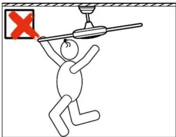
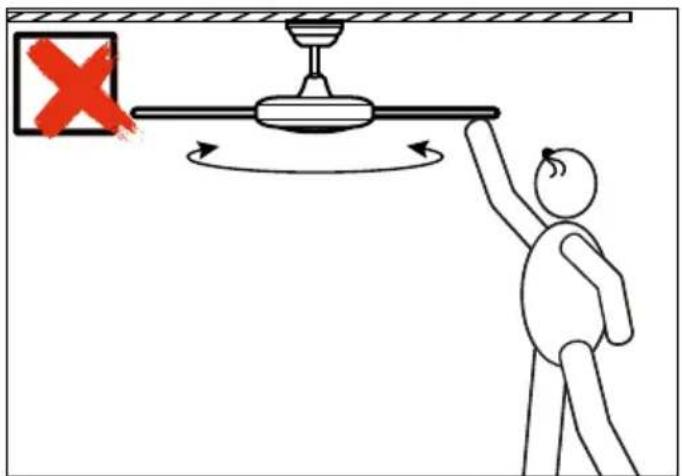
- If unusual oscillating movement is observed, immediately stop using the ceiling fan and contact the manufacturer, its service agent or suitably qualified persons.
- Replacement of parts of the safety suspension system device shall be performed by the manufacturer, its service agent or suitably qualified persons.
- Mounting of the suspension system shall be performed by the manufacturer, its service agent or suitably qualified persons.
GB
- Before accessing the connection and installation, the current must be disconnected on all poles (fuse in fuse box).
- Children shall not play with the appliance.
- Ensure that the fan is switched off from the supply mains before service and maintenance.
- The electrical connection and electrical maintenance of this fan may only be carried out by a trained electrician, a skilled electrician or an appropriately qualified person.
- The voltage details on the rating label are to conform with the available mains voltage.
- Do not run the cables over sharp edges and under no circumstances squeeze the cables during installation.
- Only operate the ceiling fan when completely assembled!
- WARNING! The mains connection requires a two-pole isolating switch with a contact opening width of at least 3 mm. The disconnecting device must be integrated into the fixed wiring according to the valid technical regulations.
- The electrical safety of the fan is only guaranteed if the earthing system of the building installation is installed in accordance with the regulations and the fan is connected to it.
- The mains connection to which the fan is connected must comply with the applicable local standards.
- Choose a safe place for installation and make sure that there are no objects within the area of rotation.
- The construction and fixture of the holder and ceiling is to be able to bear 4 times the weight of the fan when being moved.
- None of the fan blades are to be less than 2.3 m from the ground.
- Keep the fan away from heat sources. The minimum distance to radiant heaters and stoves is 1.5 m.
- Before first using after the setup, all electrical and mechanical connections are to be checked in order to prevent any fall, fire or electric shock.
Observe notes on disposal!
Our ceiling fans are quality products and designed for a long service life.
- Do not dispose of a appliance at the end of its service life and any batteries required to operate the appliance in household waste!
- Find out about local return and recycling possibilities and use the existing collection points in your area for disposal.
- Dispose of packaging material that is no longer required in an environmentally friendly manner and inaccessible to children.
- There is a risk of suffocation for children by inhaling or swallowing parts of the packaging.
PARTS (Figure U, page 28)
Unpack the fan and compare the package contents for completeness. All the parts shown in the figure are to be present and undamaged.
| Technical data: | ||
| Type CARIBBEAN DREAM | ECO II | |
| Mains voltage 100 - 240 V | ~ | |
| Frequency 50/60 Hz | ||
| Power motor 1.1 - 25.6 W | ||
| Protection class I/IP20 | ||
| No. of speeds 6 (with remote control) | ||
| Natural palm leaf PLM Antique wicker RTN | ||
| Size ∅ × H (mm) approx. 1370 × 360 1370 × 355 | ||
| Distance ceiling – blades | 340 mm | 335 mm |
| Weight (kg) | approx. 6.8 | approx. 8.6 |
| Optional light kit | available as accessory | |
| Service interval | once a year | |
| Subject to technical modifications. | ||
DE EINZELTEILE
① Hanger Bracket
② Canopy Screw (4×)
3 Terminal Block Clevis Pin
4 Safety Rope
5 Fan Wire
6 Canopy
7 Canopy Screw Cover
8 Downrod and Hanger Ball
9 Downrod Support
10 Downrod Support Screw (2×)
11 Remote Control
12 Hairpin Clip
13 Motor Assembly
14 Upper Cover
15 Blade (5×)
16. Blade Support (5×)
15. Blade Screws (15×)
17 Bottom Cover
18
19 Screw for Blade Support (10×)
20 Bracket Screw for Wood (2×)
21 Support Safety Rope
22 Transport lock (3×)
FR PIÈCE DÉTACHÉE

COMPONENTES
GB ⚠ WARNING: Danger of electric shock! Before commencing installation, turn off electricity supply at the main power box or disconnect power by removing fuse.
⚠️ ATTENTION: Follow all installation directions. Improper installation can lead to injuries and material damage.
- The place of installation (ceiling) must have a load capacity of at least 28 kg.
- Use only for your type of ceiling suitable screws and plugs (not supplied).
1 Attach the hanger bracket ① with 2 screws. Tighten the screws.
2 Fasten the hook 2 for the safety rope on the ceiling as shown.
3 Remove the 3 transport locks on the motor before starting assembly.
natural_image
Technical line drawing of a mechanical component with dashed circular outlines (no text or symbols)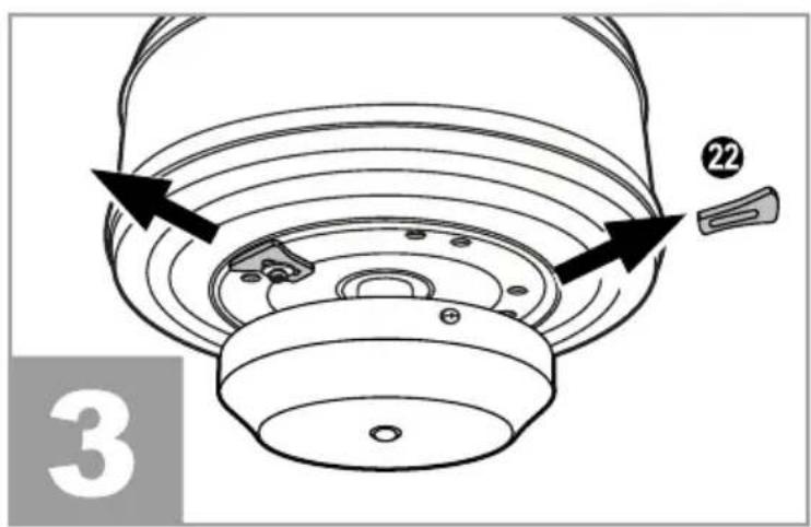
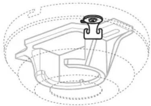
GB Uninstall the clevis pin from the downrod, retain the clevis pin and hairpin clip for later. Install the canopy, cover ring and upper cover through downrod.
DE Lösen Sie die beiden Schrauben an der Deckenstangenaufnahme am Motor.
1. Führen sie die Deckenstange in die Aufnahme ein. 2. Stecken Sie den Sicherungs- stift durch die vorgesehene Öffnung und 3. sichern Sie diesen mit dem Sicherungssplint. 4. Ziehen Sie die Schrauben an der Deckenstangenaufnahme wieder fest an.
GB Unscrew the two screws at the downrod support at the motor. 1. Insert the downrod into the support. 2. Insert the clevis pin through the opening provided and 3. secure it with the hairpin clip. 4. Tighten the two screws on the downrod support.
FR Dévissez les deux vis de la pièce du moteur destinée à recevoir la tige. 1. Mettez la tige. 2. Place et insérez la goupille d'arrêt dans l'ouverture prévue et 3. fermer avec la goupille de sécurité. 4. Resserrer les deux vis de la pièce du moteur à fond.
IT Svitare le due viti sul collegamento per l'asta soffitto sul motore. 1. Inserire l'asta di prolunga nella collegamento per l'asta soffitto. 2. Inserire il perno di bloccaggio attraverso l'apertura prevista e 3. fissarlo con la coppia. 4. Serrare le due viti sul ricevitore asta di soffitto di nuovo saldamente.
ES Afloje los dos tornillos del soporte de la varilla de techo en el motor. 1. Inserte la varilla de techo en el soporte. 2. Introduzca el pasador de bloqueo a través de la abertura prevista y 3. fijelo con la clavija dividida de bloqueo. 4. Vuelva a apretar los dos tornillos del soporte de la barra del techo.
CZ Povolte dva šrouby na držáku stropní tyče na motoru. 1. Vložte stropní tyč do držáku. 2. Zasuňte zajišťovací kolík do připraveného otvoru a 3. zajistěte jej závlačkou. 4. Znovu utáhněte dva šrouby na držáku stropní tyče.
NL Draai de twee klemschroeven van de plafondstanghouder op de motor los. 1. Steek de plafondstang in de houder. 2. Steek de borgpin door de daarvoor bestemde opening en 3. zet hem vast met de splitpen. 4. Draai de twee klemschroeven van de plafondstanghouder weer vast.
PL Poluzować dwie śruby na uchwycie pręta sufitowego na silniku. 1. Włożyć pręt sufitowy do uchwytu. 2. Włożyć sworzeń blokujący przez przewidziany w tym celu otwór i 3. zabezpieczyć go zawleczką spreężysta. 4. Ponownie dokręcić dwie śruby na uchwycie pręta sufitowego.
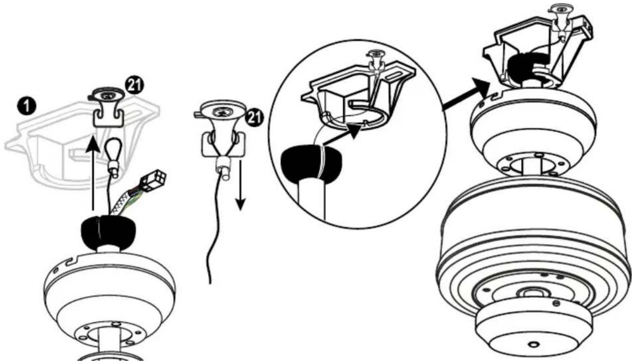
GB Hang the pre-mounted ceiling fan into the ceiling bracket. Hang the safety cable in the hook provided for this purpose and pull it tightly downwards to secure it against leaking. Make the electrical connection as shown on page 38/39.
natural_image
Diagram showing two types of cable connectors with directional arrows indicating movement (no text or symbols)GB Plug the two connectors together to provide power to the motor.
GB Slide the canopy up and twist it into the bayonet lock with the canopy screws. Fasten the 4 canopy screws.
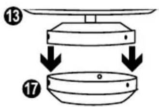
DE Lösen Sie die Schrauben an der unteren Abdeckung und nehmen Sie diese ab.
GB Loosen the screws on the bottom cover and remove it.
FR Desserrer les vis du couvercle inférieur et le retirer.
IT Allentare le viti del coperchio inferiore e rimuoverlo.
ES Afloje los tornillos de la tapa inferior y retírela.
CZ Uvolněte šrouby na spodním krytu a sejměte jej.
NL Draai de schroeven van het onderste afdekking los en verwijder het.
PL Poluzować śruby dolnej pokrywy i zdjąć ją.
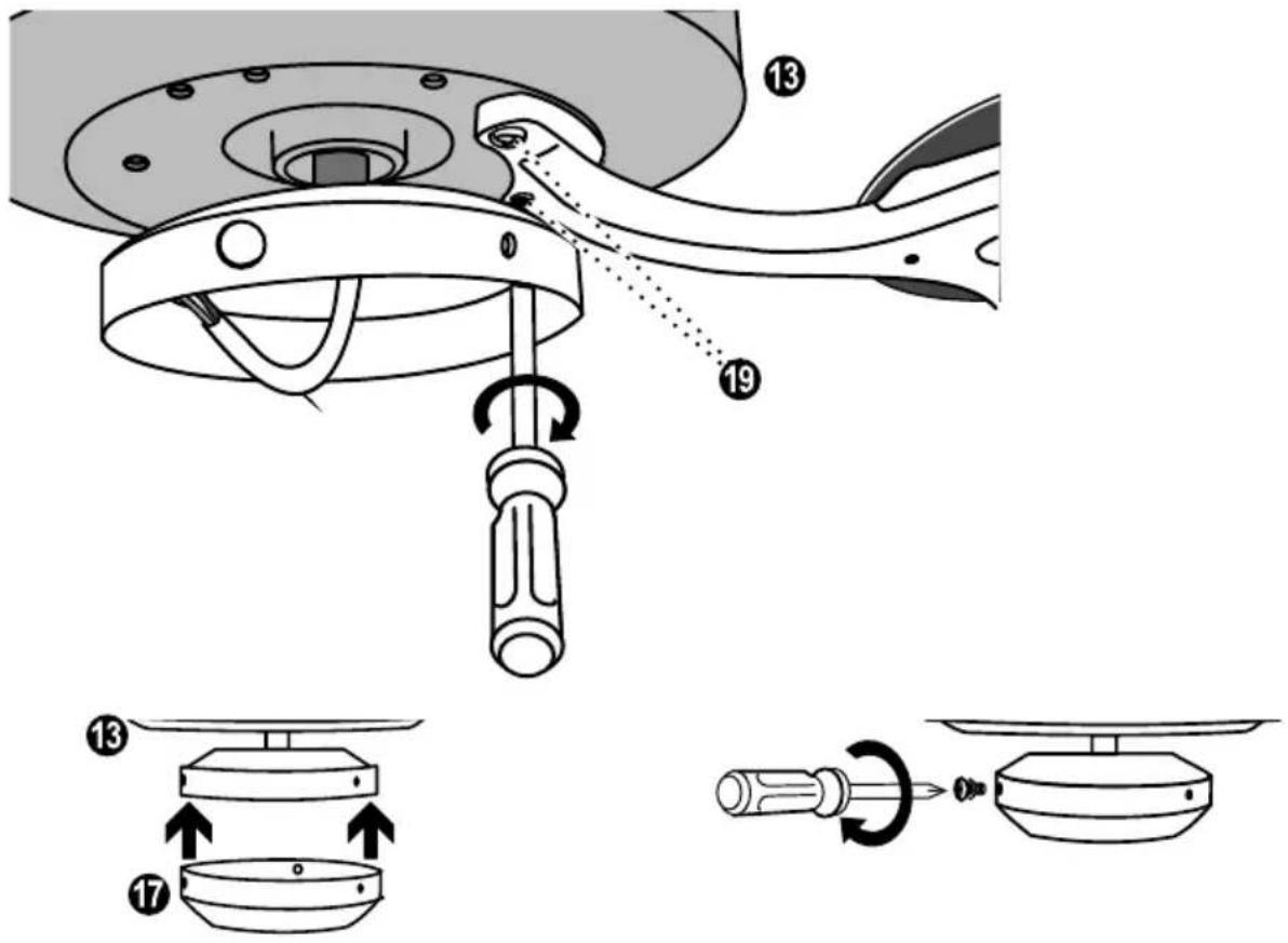
[GB] Attach the 5 blades to the motor with 2 blade holder screws each. Put on the lower cover and fix it with 3 screws. - Your ceiling fan is now ready to run for the first time.
- Several ceiling fans can be connected to a single hand-held transmitter.
- If several fans within radio range are to be programmed on their own hand-held transmitters, only the fan currently to be programmed must be switched on. The same applies to reprogramming and teaching new blade sizes and numbers.
FR NOTE SUR LA TÉLÉCOMMANDE
GB Insert 1 battery type 6F22 (9V) into the transmitter of the remote control. Do not press any button yet!
GB Switch on the electricity supply for the ceiling fan (fuse).
GB Within first 60 seconds after power on: Press the "OFF" button until you hear two BEEP tones until confirmed.
GB Teach-in size and number of blades
GB Within the first 120 seconds after switching on the power and inserting the battery: Press the “FAN” button until you hear 3 BEEP tones.
- The motor will now run from maximum speed to standstill. The highest level is indicated in the display of the remote control. - At the end of the teach-in procedure, another 3 BEEP tones will sound for confirmation. Your ceiling fan is now ready for operation.
GB Press the "FAN" button to start the fan on low speed.
natural_image
Simple diagram showing a cross-shaped symbol with an arrow and a curved line, next to a vertical bar (no text or labels)GB Pressing the "FAN" button again will switch the fan motor one step faster.
natural_image
Pure diagram of a wind turbine blade and arc without any text or symbolsGB Press the "F/R" button to change the direction of rotation.
GB While the motor is running, press the ⏻ button to set the shutdown timer. When the set time has elapsed, the fan switches off.
GB Each press on this button increases the time of the shutdown timer by one hour.
GB Press the "OFF" button to turn off the ceiling fan.
NOTE: The luminaire is optional and is not supplied with your ceiling fan.
natural_image
Pure diagram of a helicopter above an arc with a vertical scale bar (no text or symbols)natural_image
Pure diagram of a helicopter and arc without any text, numbers, or symbolsGB Press the "LIGHT" button again to turn off the optional light kit.
| GB NOTES FOR REMOVING FAULTS | |
| Fault Remedy | |
| The fan does not start | - Check the fuses/trips at the main box and other connections.- Check the fan connection to the mains.- Repeat coding of the fan with the handheld transmitter.- Replace the battery in the handheld transmitter if necessary. |
| The fan is noisy - | Check that all bolts and screws have been tightened.- Run in the fan and the bearings for 24 hours. Most noises disappear after this time. |
| The fan vibrates too much | - All screws during assembly of the ventilator, especially those relating to the downrod, have an important function. Not tightened screws are the main cause of imbalances. Please make sure that all screws are tightened.- All blades have been weighed and grouped according to weight. Wood is a natural material. Their density can vary and therefore cause vibration even when all blades are of the same weight. If the blade screws of one of the blades are not tightened properly, this could cause massive wobbling.NOTE: Movement of up to 10 mm is quite acceptable and does not mean a faulty ceiling fan.- Check that the hanger bracket is firmly anchored to the ceiling. |
| Important:Opening up and repairing the unit may only be carried out by a qualified electrician! | |
CLEANING/MAINTENANCE

WARNING: Danger of electric shock! Turn off the electricity at the fuse
box or circuit breaker before cleaning or servicing your fan.
- Never use water for cleaning your ceiling fan. The appliance must not get wet.
- Do not use petrol or any similar light flammable detergents!
- Clean the surface of the housing and the blades with a dry cleaning cloth.
Regular check
- Check once a year all the screws, especially those of the ceiling suspension, for tightness, retighten if necessary.
- Check electrical connections for proper connection.
Lock protection: The EC/DC motor has a built-in safety feature against blade or motor obstruction during operation. If something obstructs the fan blades or motor, the motor will keep trying to run and then stop operation after about 30 seconds of interruption. Please remove obstacles and reset.
To reset: Turn the fan off by remote transmitter. Turn the fan on again after 10 seconds. Over load protection (current limit): The device will limit the maximum current output from the receiver/drive if the fan load has increased abnormally.
Tips
- If your fan is operates automatically after installation and power on, it is because your fan has memorized the previous factory setting. Use the Universal Mode or the learning function and your fan will be ready for use.
- If the fan or light isn't working, reset power (turn the power off for at least 10 seconds and then turn the power back on) and redo the learn function setting.
- It is not possible to remotely operate more than one fan in the same room (in the area where the remote signal can reach to) if they share the same power supply. Separate power supplies (such as using individual wall switches for each fan) is required if you want to separately control more than one fan in same room.
- When the fan is turned on or operated using forward/reverse function, it shutters & goes back & forth until it turns. This is normal and it will take a few seconds to run this operation.
The packaging is made of environmentally friendly materials that you can dispose of at local recycling points.


The labelling of packaging materials helps with waste separation, these are marked with abbreviations (a) and numbers (b). These have the following meaning: 1 - 6 = plastics / 20 - 22 = paper and cardboard / 80 - 99 = composites.
The product and packaging materials are recyclable, dispose of them separately for better waste treatment. The Triman logo is only valid for France.
Do not throw electrical appliances and portable batteries in the household waste!
According to the European Directive 2012/19/EU on waste electrical and electronic equipment and its implementation in national law, used electrical equipment and waste batteries must be collected separately and recycled in an environmentally sound manner.
In the interest of environmental protection, do not dispose of the product in household waste, but recycle it properly. You can obtain information about collection points from your specialist dealer or your local administration.
FR MISE AU REBUT
EU Declaration of Conformity
Wir, die Firma
CasaFan GmbH
We, the company Senefelderstr. 8
Hasselroth, 63594, Germany
declare under our sole responsibility that the following product
Geräteart/ type of product:
Deckenventilator / ceiling fan
Handelsmarke/ trademark:
CasaFan
meets the essential requirements of the following EU-Directives:
2014/53/EC Radio Equipment Directive [OJEU L153/62-106, 22.05.2014]
2011/65/EC
Directive on the restriction of the use of certain hazardous substances in electrical and electronic equipment [OJEU L174/88-110, 01.07.2011]
2009/125/EC
Ecodesign directive [OJEU L285/10-35, 31.10.2009]
Authorized person for technical documentation:
natural_image
Simple line drawing of a bottle with a handle and spout (no text or symbols)natural_image
Three line drawings of a bottle with handles and droplets, shown from different angles (no text or symbols)natural_image
Line drawings of four different types of household appliances or fixtures, including a conical lamp and a triangular device (no text or symbols present)natural_image
Line drawings of four different types of ceiling fixtures with droplet placements (no text or symbols)CasaFan reserves the right to make any changes to the product without prior notice.